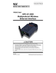
1
Instruction Manual OPC-PRT2 PROFINET IO Interface Thank you for purchasing the OPC-PRT2 PROFINET IO Interface. • This product is designed to connect the FRENIC-MEGA and FRENIC-HVAC series of inverters to PROFINET networks. Please read this instruction manual thoroughly in order to become familiar with the proper interface handling, installation and usage procedures. • Improper handling may inhibit correct operation or cause premature interface failure. • Please deliver this instruction manual to the end user of the interface, and retain it in an accessible location. • For inverter usage instructions, please refer to the applicable inverter instruction manual. July 28, 2015 Part #10946 © 2015 Fuji Electric OPC-PRT2 PROFINET IO Interface Instruction Manual Part Number 10946 Printed in U.S.A. ©2015 Fuji Electric. All rights reserved Fuji Electric reserves the right to make changes and improvements to its products without providing notice. Notice to Users PRODUCTS ARE NOT AUTHORIZED FOR USE AS CRITICAL COMPONENTS IN LIFE-SUPPORT DEVICES OR SYSTEMS. Life-support devices or systems are devices or systems intended to sustain life, and whose failure to perform, when properly used in accordance with instructions for use provided in the labeling and user's manual, can be reasonably expected to result in significant injury. No complex software or hardware system is perfect. Bugs may always be present in a system of any size. In order to prevent danger to life or property, it is the responsibility of the system designer to incorporate redundant protective mechanisms appropriate to the risk involved. 1 Preface This instruction manual has been prepared to help you connect your FRENIC-MEGA or FRENIC-HVAC inverter to a PROFINET IO network using the OPC-PRT2 PROFINET IO interface card. This instruction manual does not contain inverter usage instructions. Please refer to this instruction manual in conjunction with the applicable inverter instruction manual in order to become familiar with the proper handling, installation and operation of this product. Improper handling or installation procedures may result in incorrect operation or premature product failure. Related Publications Listed below are publications that are necessary for reference in conjunction with this instruction manual. • RS-485 Communication User's Manual (24A7-E-0082) • FRENIC-MEGA Instruction Manual (INR-SI47-1457-E) • FRENIC-HVAC Instruction Manual (INR-S147-1610-E) • FRENIC-MEGA User’s Manual (MEHT536) • FRENIC-HVAC User’s Manual (24A7-E-0069) These documents are subject to change without notice. Please be sure to refer to the most recent available versions. Safety precautions Please read this instruction manual thoroughly prior to proceeding with installation, connections, operation, or maintenance and inspection. Additionally, ensure that all aspects of the system are fully understood, and familiarize yourself with all safety information and precautions before operating the inverter. Safety precautions in this instruction manual are classified into the following two categories: Failure to heed the information indicated by this symbol may lead to dangerous conditions, possibly resulting in death or serious bodily injuries. Failure to heed the information indicated by this symbol may lead to dangerous conditions, possibly resulting in minor or light bodily injuries and/or substantial property damage. Failure to heed the information contained under the CAUTION title can also result in serious consequences. These safety precautions are of utmost importance and must be observed at all times. 2 Installation and Wiring • To avoid electrical shock, remove all power from the inverter and wait at least five minutes prior to starting installation. Additionally, confirm that the DC link bus voltage as measured between the P (+) and N (-) terminals is less than 25 VDC. • Installation should be performed only by qualified personnel. • To avoid electrical shock, do not operate the inverter with the front cover or wiring cover removed, as accidental contact with exposed high-voltage terminals and internal components may occur. • To prevent explosions or similar damage, ensure that all cables are properly connected to the correct terminals, and observe all wiring polarity indicators. • Do not install or operate the interface if it is damaged or has parts missing. • Prevent conductive items such as screws and metal fragments, or flammable substances such as oil, lint, paper fibers and sawdust from entering the inverter and interface card enclosure. • Incorrect handling during installation or removal may cause equipment failure. • Do not subject the cables to scratches, excessive stress, heavy loads or pinching. • To prevent damage due to electrostatic discharge, always touch a grounded piece of metal prior to touching any equipment. • Do not stand on or rest heavy objects on the equipment. • To prevent burns from hot components, do not touch the inverter while power is on, or for some time after power is removed. • Electrical noise may be emitted from the inverter, motor and wires. Always implement appropriate countermeasures to prevent nearby sensors and devices from malfunctioning due to such noise. Operation • To avoid electrical shock, do not open the front cover of the inverter while power is on or while the inverter is running. • To avoid electrical shock, do not operate switches with wet hands. • If the inverter’s function codes are incorrectly configured, or configured without adequate understanding of the appropriate inverter Instruction Manual and User's Manual, the motor may rotate with a torque or at a speed not permitted for the machine. Confirm the settings of all function codes prior to running the inverter. 3 Maintenance, inspection, and parts replacement • To avoid electrical shock, remove all power from the inverter and wait at least five minutes prior to starting inspection. Additionally, confirm that the DC link bus voltage as measured between the P (+) and N (-) terminals is less than 25 VDC. • Maintenance, inspection, and parts replacement should be performed only by qualified personnel. • Remove all watches, rings and other metallic objects prior to starting work. • To avoid electrical shock or other injuries, always use insulated tools. Disposal • Contact the local or state environmental agency in your area for details on the disposal of electrical components and packaging. Other • Do not attempt to modify the equipment: doing so may cause electrical shock or injuries. • For clarity purposes, illustrations in this manual may be drawn with covers or safety guards removed. Ensure all covers and safety guards are properly installed prior to starting operation. • Do not perform hi-pot tests on the equipment. • Performing a data initialization (function code H03) may reset all inverter function codes to their factory default settings. After performing this operation, remember to reenter any custom function code values prior to starting operation. Icons The following icons are used throughout this manual: Indicates information which, if not heeded, can result in the product not operating to full efficiency, as well as information concerning incorrect operations and settings which may result in accidents. Indicates information that can prove handy when performing certain settings or operations. Indicates a reference to more detailed information. 4 − TABLE OF CONTENTS − 1 PRE-OPERATION INSTRUCTIONS ........................................................... 7 1.1 Product Overview .................................................................................................... 7 1.2 Features and Specifications ................................................................................... 7 1.3 Unpacking and Product Confirmation ................................................................. 10 1.3.1 1.3.2 1.4 LED Indicators ....................................................................................................... 13 1.4.1 1.4.2 1.4.3 2 3 4 5 2.1 Pre-Installation Instructions ................................................................................. 14 2.2 Installation Procedure ........................................................................................... 14 INVERTER FUNCTION CODE SETTINGS ............................................... 16 3.1 Inverter Control-Related Settings ........................................................................ 16 3.2 Inverter Reaction to Network Timeout Conditions ............................................ 17 FUNCTION CODE NUMBERING AND BEHAVIOR .................................. 18 4.1 Register Numbers .................................................................................................. 18 4.2 Scanned Function Codes ..................................................................................... 21 4.3 Commonly Used Function Codes ........................................................................ 21 FUJI CONFIGURATION STUDIO ............................................................. 23 5.1 Overview ................................................................................................................. 23 5.2 General Object Editing Activities ......................................................................... 25 5.3 Ethernet Settings ................................................................................................... 26 5.4 Authentication ..................................................................................................................26 Network Configuration .....................................................................................................26 Internal Logic Settings .......................................................................................... 26 5.4.1 5.4.2 Fail-safe Values ...............................................................................................................26 Fail-safe Example ............................................................................................................27 5.5 Discovery over Ethernet ....................................................................................... 28 5.6 Manage Device Parameters .................................................................................. 28 5.7 5.8 Backup and Restore Parameters ......................................................................... 29 Restore Factory Settings ...................................................................................... 30 5.9 Help ......................................................................................................................... 30 EMBEDDED WEB SERVER ..................................................................... 31 6.1 Overview ................................................................................................................. 31 6.2 Monitor Tab ............................................................................................................ 31 6.2.1 6.2.2 6.2.3 6.2.4 5 Network Status LED ........................................................................................................13 Module Status LED ..........................................................................................................13 Ethernet Link/Activity LEDs ..............................................................................................13 INSTALLATION ....................................................................................... 14 5.3.1 5.3.2 6 Shipment Confirmation ....................................................................................................10 Component Overview ......................................................................................................11 Information Window .........................................................................................................31 Function Code Group Selection List .................................................................................32 Function Code List ...........................................................................................................32 Function Code List Filter ..................................................................................................33 6.2.5 6.3 6.3.1 6.3.2 6.3.3 6.3.4 6.3.5 6.4 File System ............................................................................................................. 44 7.1.1 7.1.2 7.1.3 7.1.4 7.2 Overview .........................................................................................................................44 USB with Windows Explorer ............................................................................................44 FTP with Windows Explorer .............................................................................................45 Loading New Web Server Content ...................................................................................45 Firmware ................................................................................................................. 46 7.2.1 7.2.2 Overview .........................................................................................................................46 Update Procedure............................................................................................................46 PROTOCOL-SPECIFIC INFORMATION ................................................... 47 8.1 PROFINET IO .......................................................................................................... 47 8.1.1 8.1.2 8.1.3 8.1.4 8.1.5 8.1.6 8.1.7 9 Customization Overview ..................................................................................................41 XTPro Overview ..............................................................................................................41 XTPro Web Browser-Based Implementation ....................................................................42 XTPro HMI-Based Implementation ...................................................................................43 XTPro Supported Commands ..........................................................................................43 FILE SYSTEM & FIRMWARE ................................................................... 44 7.1 8 Information Window .........................................................................................................35 Virtual Keypad .................................................................................................................36 Gauge Window Navigation...............................................................................................37 Gauge Window Configuration ..........................................................................................37 Submitting Changes ........................................................................................................40 Customizing the Embedded Web Server ............................................................ 41 6.4.1 6.4.2 6.4.3 6.4.4 6.4.5 7 Radix Selection ................................................................................................................33 Dashboard Tab ....................................................................................................... 35 Overview .........................................................................................................................47 Device Settings ................................................................................................................47 Connection Timeout Options............................................................................................47 Cyclic I/O Produced and Consumed Data Access Settings ..............................................48 PROFIdrive Profile ...........................................................................................................49 Acyclic Data Access ........................................................................................................52 STEP 7 Hardware Configuration Example .......................................................................52 TROUBLESHOOTING.............................................................................. 57 6 1 PRE-OPERATION INSTRUCTIONS 1.1 Product Overview The OPC-PRT2 PROFINET IO interface allows information to be transferred seamlessly between a FRENIC-MEGA or FRENIC-HVAC inverter and a PROFINET controller with minimal configuration requirements. The interface installs directly onto the inverter, and presents two RJ-45 jacks with an embedded 10/100BaseT Ethernet switch for connection to the Ethernet network. In addition to the supported fieldbus protocols, the interface also hosts a fully-customizable embedded web server, which provides access to inverter information via a standard web browser for remote monitoring and control. Before using the interface, please familiarize yourself with the product and be sure to thoroughly read the instructions and precautions contained in this manual. In addition, please make sure that this instruction manual is delivered to the end user of the interface, and keep this instruction manual in a safe place for future reference or unit inspection. Note that different interface firmware versions may provide varying levels of support for the various protocols. When using this manual, therefore, always keep in mind the release date of the firmware version running on your interface as it must correspond to this manual’s respective release date in order for all documented aspects to apply. Supported Protocols The interface currently provides server support for the following fieldbus protocols: PROFINET IO Device (MRP client) • 1.2 Features and Specifications Table 1: Features Item Description Simultaneous Protocols Supports all standard unmodified Ethernet (SUE) protocols simultaneously Fuji Configuration Studio Graphical user interface for discovery, configuration, and firmware update WEB Server (HTTP) Access all parameters, dashboard with gauges, customizable with XTPro Communication Loss Detection Field Upgradeable Configurable actions for “fail-safe” conditions Firmware updates automatically handled by the studio Parameter Management Advanced management of parameter access and scan priority Parameter Backup and Restore Drive cloning Table 2: General Hardware Specifications Item Power Supply Directly powered by the inverter LED Indicators Module Status, Network Status, 2 x Ethernet Link/Activity USB Port 7 Description USB 2.0, mini-B 5-pin Table 3: Ethernet Hardware Specifications Item Number of Ports Standard Communication Speed and Duplex Connector Type Description 2 (internal switch) IEEE 802.3 10/100BaseT Ethernet compliant 10Mbps half/full, 100Mbps half/full (auto sense optimal speed and duplex) RJ-45 Shielded Auto MDI-X Yes (supports all straight-through and cross-over cables) Cable Type CAT5-type 8-conductor UTP patch cables Cable Length Topologies 100m per segment max Star/Tree, Linear/Bus/Daisy-chain, Ring (MRP) Table 4: PROFINET Specifications Item Protocol Level Description RT (real-time) RT Conformance Class Class A I/O Cycle Time Min 1ms I/O Input Size Max 32 input words, user configurable I/O Output Size Max 32 output words, user configurable MRP Media Redundancy Protocol Client DCP Discovery, set station name, set IP address LLDP Yes I&M Alarms Number of Controllers I&M0 Plug, Pull Allows access to only 1 controller Table 5: Applicable Inverters Series Type Capacity ROM version FRENIC-MEGA FRN□□□G1□-□□ All capacities 1000 or higher FRENIC-HVAC FRN□□□AR1□-□□ All capacities 1100 or higher 8 Table 6: Environmental Specifications Item Operating Environment Indoors, less than 1000m above sea level, do not expose to direct sunlight or corrosive / explosive gasses Operating Temperature -10 ∼ +50°C (+14 ∼ +122°F) Storage Temperature -40 ∼ +85°C (-40 ∼ +185°F) Relative Humidity 20% ∼ 90% (without condensation) Vibration 5.9m/s (0.6G) or less (10 ∼ 55Hz) Cooling Method RoHS (Lead free) 9 Description 2 Self-cooled Yes 1.3 Unpacking and Product Confirmation 1.3.1 Shipment Confirmation Check the enclosed items. Confirm that the correct quantity of each item was received, and that no damage occurred during shipment. • OPC-PRT2 interface board with spacer and captive M3 x 25mm screw in lower-right corner (see Figure 1). • One separate M3 x 6mm mounting screw (see Figure 2). • Type A male to mini-B male USB interface cable (see Figure 3). Figure 2: M3 x 6mm Mounting Screw Figure 1: OPC-PRT2 Interface Board Figure 3: USB Interface Cable 10 1.3.2 Component Overview Figure 5 and Figure 6 provide an overview of the important interface card components. Positioning notch Port 1 Ethernet jack Port 2 Ethernet jack Spacer and captive screw Figure 4: OPC-PRT2 Component Overview (Front View) MAC Address Inverter control board connector USB port Module Status LED Network Status LED Port 1 Link/Activity LED Port 2 Link/Activity LED Standoff mounting hole Figure 5: OPC-PRT2 Component Overview (Reverse View) 11 Positioning Notch Aligns with the positioning key on the inverter chassis to ensure that the interface card is installed into the correct communication port (refer to section 2.2). Port 1 and Port 2 Ethernet Jacks Either jack can freely be used in star topology networks (with external switch). In linear topologies, a series of cards can be connected together by daisy-chaining one of the ports to the next inverter in line. In ring topologies, MRP (Media Redundancy Protocol) must be supported by all devices on the network. Standoff Mounting Hardware The provided M3 x 25mm and M3 x 6mm screws are used to secure the card to the standoffs located on the inverter’s control board. Refer to section 2.2. Inverter Control Board Connector Attaches to the “A-port” on the inverter’s control board. USB Port USB 2.0 port with mini-B connector. Used to access the card via the Fuji Configuration Studio (refer to section 5) and as a USB flash drive (refer to section 7.1). Module Status and Network Status LEDs These LEDs indicate the current status of the interface card and protocols in use. Refer to section 1.4. Ethernet Link and Activity LEDs One set of LEDs are provided for each Ethernet port. These LEDs provide insight into the Ethernet network’s status and activity. Refer to section 1.4. 12 1.4 LED Indicators 1.4.1 Network Status LED LED Activity Status Off No Connection Green Blink / Red Blink Startup Green On Connection Established Note PROFINET connection is not established Startup blink sequence PROFINET connection is established 1.4.2 Module Status LED LED Activity Status Note Off Device Off The inverter power is off Green Blink / Red Blink Startup Startup blink sequence Green On Device On Green Blink Discovery identification PROFINET discovery and identification (DCP) Red Blink Error Code Record the error code sequence and contact technical support Normal status 1.4.3 Ethernet Link/Activity LEDs 13 LED Activity Status Note Green On Link Green Off No Link A valid Ethernet link does not exist: communication is not possible on this port Red Blink Activity Indicates when a packet is transmitted or received on this port A valid Ethernet link exists: communication is possible on this port 2 INSTALLATION 2.1 Pre-Installation Instructions • To avoid electrical shock, remove all power from the inverter and wait at least five minutes prior to starting installation. Additionally, confirm that the DC link bus voltage as measured between the P (+) and N (-) terminals is less than 25 VDC. • Installation should be performed only by qualified personnel. • To avoid electrical shock, do not operate the inverter with the front cover or wiring cover removed, as accidental contact with exposed high-voltage terminals and internal components may occur. • To prevent explosions or similar damage, ensure that all cables are properly connected to the correct terminals, and observe all wiring polarity indicators. • Only one additional option card may be used when the OPC-PRT2 is installed in the inverter. If two additional option cards are required, please consult with the factory first to confirm compatibility. 2.2 Installation Procedure Before installing the interface card, perform all wiring for the main circuit terminals and control circuit terminals. 1. Remove the front cover from the inverter to expose the control printed circuit board (control PCB). As shown in Figure 6, there are three option connection ports (A-port, B-port and C-port). The card is mechanically keyed for, and can only be installed into, the A-port (bottom-most) position. To remove the front cover, refer to the FRENIC-MEGA Instruction Manual, Chapter 2, Section 2.3 or FRENIC-HVAC Instruction Manual, Chapter 2, Section 2.2. Figure 6: Option Port Locations on 0.4 kW Inverter 14 2. Rest the left-hand side of the interface card on the control PCB’s A-port mounting support. Align the positioning notch on the interface card with the A-port positioning key, and then slide the interface card to the left to engage the key into the notch. Refer to step in Figure 7. 3. Rotate the right-hand side of the interface card downward to engage connector CN1 (on the back of the interface card) into the A-port connector (CN4) on the inverter’s control PCB. Ensure that the connectors are fully engaged. Refer to step in Figure 7. To ensure that the interface card is fully aligned and seated into the communication port, be sure to perform steps and in the proper order. Failure to do so may lead to insufficient connector insertion and result in contact failure. Positioning Key Figure 7: Mounting the Interface Card 4. Secure the interface card to the control board PCB by first tightening the captive M3 x 25mm screw into the inverter standoff located at the lower-right hand corner of the interface card. Next, install and tighten the included M3 x 6mm screw into the standoff mounting hole located at the upper-left hand corner of the interface card. Refer to Figure 8. Figure 8: Interface Card Mounting Completed 5. Connect the network cables as necessary. Insert the Ethernet cables into the Ethernet jacks, making sure that they are fully seated. Ensure that the cables are routed in such a way that they will not be pinched and are not located near any power-carrying wiring, such as the inverter’s input power or motor wires. 6. Reinstall all covers removed in step 1. Take a moment to confirm that the Ethernet cables are not being pinched and are not routed near any power-carrying wiring. 15 For reinstallation instructions, refer to the FRENIC-MEGA Instruction Manual, Chapter 2, Section 2.3 or FRENIC-HVAC Instruction Manual, Chapter 2, Section 2.2. 3 INVERTER FUNCTION CODE SETTINGS Depending on the desired operation of the overall application, the inverter function codes listed in Table 7 are important for proper operation of the end-to-end communication system. Although there may be many other function codes that will require configuration for your specific application, it is important to understand the manner in which the following function codes will impact successful control of the inverter. For further details regarding these function codes, please refer to the FRENIC-MEGA Instruction Manual (INR-SI47-1457-E) or FRENIC-HVAC Instruction Manual (INR-SI471610-E), Chapter 5 "FUNCTION CODES", FRENIC-MEGA User’s Manual (MEHT536) or FRENIC-HVAC User’s Manual (24A7-E-0069), “y codes: Link Functions”, and RS-485 Communication User's Manual (24A7-E-0082), Chapter 5, Section 5.2 "Data Formats." Table 7: Function Code Settings Overview 3.1 Code Name Setting Range Required Value Y98 Bus Link Function (Mode Selection) 0 to 3 3 Inverter Control-Related Settings The following function codes relate to whether or not the inverter is to be controlled (command word and/or frequency command) from the network, or whether the inverter will be locally-controlled (and therefore only monitored and/or configured via the network.) Bus Link Function (Mode Selection) (y98) If the inverter is to be controlled from the network, then set the value of y98 to 3 (fieldbus option). A setting of 3 for y98 may also be appropriate even if H30 is configured for an alternate (local) control scheme. When the inverter is controlled from the network, a selection of reference commands (S## function codes as defined in Table 8) are available for controlling the inverter’s speed. If multiple reference commands are being modified from the network, then the interface card invokes a hierarchy to determine which reference is to be passed to the inverter as its main reference command. The S## function code hierarchy is listed from highest to lowest priority in Table 8. Table 8: S## Function Code Hierarchy S## Function Code S01 S05 S19 S02 Hierarchy Priority Description Highest frequency reference / per-unit nd frequency reference / Hz rd speed command th torque command th 2 Highest 3 Highest 4 Highest S03 5 Highest torque current command S13 Lowest PID command The highest-priority S## function code with a non-zero value will be used as the inverter’s main reference command. 16 3.2 Inverter Reaction to Network Timeout Conditions Function codes o27 and o28 specify the inverter’s reaction when a network timeout occurs. Table 9 lists the settings for o27 and o28. Table 9: Inverter Reaction to Network Timeout Conditions (Function Codes o27 and o28) o27 Value o28 Value Inverter reaction when a timeout occurs 0, 4 to 9 --- Immediately coast to a stop and trip er5. 1 0.0s to 60.0s After the time specified by o28, coast to a stop and trip er5. 2 0.0s to 60.0s If the communications link is restored within the time specified by o28, ignore the communications error. After the timeout, coast to a stop and trip er5. 3, 13 to 15 --- Maintain present operation, ignoring the communications error (no er5 trip). 10 --- Immediately decelerate to a stop. Trip er5 after stopping. Inverter function code F08 specifies the deceleration time 11 0.0s to 60.0s After the time specified by o28, decelerate to a stop. Trip er5 after stopping. Same as above 12 0.0s to 60.0s If the communications link is restored within the time specified by o28, ignore the communications error. After the timeout, decelerate to a stop and trip er5. Same as above 17 Remarks For details regarding the interface-specific timeout behavior and configuration, please refer to section 5.4.1. 4 4.1 FUNCTION CODE NUMBERING AND BEHAVIOR Register Numbers All accessible inverter function codes can be referenced by their Modbus register indexes, as defined in the RS-485 Communication User’s Manual (24A7-E-0082), section 3 (Table 3.2). These same register numbers are used when accessing function codes via certain Ethernet protocols. The terms “function code” and “register” refer to data stored on the inverter and will be used interchangeably throughout this documentation. The max supported register number is 13668. Because the RS-485 User’s Manual contains information for several Fuji inverter families, the relevant information will be paraphrased here for the specific case of the FRENIC-MEGA and FRENIC-HVAC. All inverter function codes are exposed as register indexes according to a mathematical conversion formula which combines two elements (a function code group number and function code offset) to create a unique register number for each function code. Each function code group (“E” / Extension Terminal Functions, for example) is assigned a specific function code group number (refer to Table 10). Each function code also has an offset number, which is the function code without the leading letter (the offset number for function code E05, for example, is 5). To determine the register number for a given function code, therefore, the group number is first multiplied by 256, then added to the offset number plus 1. This operation is expressed mathematically via Equation 1. register = (group number x 256 ) + offset number + 1 Equation 1 As an example, let’s calculate the register number for output frequency (function code M09). According to Table 10, the group number for the “M” function code group is 8. It is also evident that the offset number for M09 is 9. Inserting the group number and offset number into Equation 1, we arrive at the result indicated in Equation 2. (8 x 256 ) + 9 + 1 = 2058 Equation 2 While manually calculating all of the register numbers for the function codes of interest is certainly possible by using Equation 1, it may be more convenient to simply reference the “Register” column on the monitor tab of the default web interface (refer to section 6.2.3). Note that not all of the available registers that exist in the interface card’s register map have corresponding function codes that exist in the inverter. In other words, if a read from or write to a register number that does not correspond to an existing inverter function code takes place, the read/write may be successful (depending on the specific register accessed; refer to section 4.2), but the data will have no meaning. This feature is beneficial in situations where the accessing of non-contiguous registers can be made more efficient by accessing an all-inclusive block of registers (some of which correspond to inverter function codes and some of which do not), while only manipulating those in your local programming that are known to exist. 18 Table 10: Function Code-to-Register Conversion Examples Function Code Group Group Number Register Example Using Equation 1 Code Name F Fundamental Functions 0 F00: (0 x 256) + 0 + 1 = 1 ... F07 (acceleration time 1): (0 x 256) + 7 + 1 = 8 ... F99: (0 x 256) + 99 + 1 = 100 E Extension Terminal Functions 1 E00: (1 x 256) + 0 + 1 = 257 … E98 (terminal [FWD] function): (1 x 256) + 98 + 1 = 355 E99: (1 x 256) + 99 + 1 = 356 C Control Functions 2 C00: (2 x 256) + 0 + 1 = 513 … C20 (jogging frequency): (2 x 256) + 20 + 1 = 533 … C99: (2 x 256) + 99 + 1 = 612 P Motor 1 Parameters 3 P00: (3 x 256) + 0 + 1 = 769 … P03 (motor 1 rated current): (3 x 256) + 3 + 1 = 772 … P99: (3 x 256) + 99 + 1 = 868 H High Performance Functions 4 H00: (4 x 256) + 0 + 1 = 1025 … H11 (deceleration mode): (4 x 256) + 11 + 1 = 1036 … H99 (4 x 256) + 99 + 1 = 1124 A Motor 2 Parameters 5 A00: (5 x 256) + 0 + 1 = 1281 … A05 (motor 2 torque boost): (5 x 256) + 5 + 1 = 1286 … A99: (5 x 256) + 99 + 1 = 1380 o Operational Functions 6 o00: (6 x 256) + 0 + 1 = 1537 o01: (6 x 256) + 1 + 1 = 1538 … o99: (6 x 256) + 99 + 1 = 1636 S Command Data 7 S00: (7 x 256) + 0 + 1 = 1793 … S05 (frequency command): (7 x 256) + 5 + 1 = 1798 … S99: (7 x 256) + 99 + 1 = 1892 8 M00: (8 x 256) + 0 + 1 = 2049 … M09 (output frequency): (8 x 256) + 9 + 1 = 2058 … M99: (8 x 256) + 9 + 1 = 2148 10 r00: (10 x 256) + 0 + 1 = 2561 … r02 (motor 2 base frequency): (10 x 256) + 6 + 1 = 2563 … r99: (10 x 256) + 99 + 1 = 2660 19 M Monitor Data 1 r Motor 4 Parameters Function Code Group Group Number Register Example Using Equation 1 Code Name J Application Functions 1 13 J00: (13 x 256) + 0 + 1 = 3329 … J03 (PID proportional gain): (13 x 256) + 3 + 1 = 3332 … J99: (13 x 256) + 99 + 1 = 3428 y Link Functions 14 y00: (14 x 256) + 0 + 1 = 3585 … y98 (bus link function): (14 x 256) + 98 + 1 = 3683 y99: (14 x 256) + 99 + 1 = 3684 W Monitor Data 2 15 W00: (15 x 256) + 0 + 1 = 3841 … W32 (PID output): (15 x 256) + 32 + 1 = 3873 … W99 (15 x 256) + 99 + 1 = 3940 X Alarm Data 1 16 X00 (alarm history / latest): (16 x 256) + 0 + 1 = 4097 … X99: (16 x 256) + 99 + 1 = 4196 17 Z00: (17 x 256) + 0 + 1 = 4353 … rd Z53 (3 last alarm torque): (17 x 256) + 53 + 1 = 4406 … Z99: (17 x 256) + 99 + 1 = 4452 18 b00: (18 x 256) + 0 + 1 = 4609 … b12 (motor 3 starting frequency): (18 x 256) + 12 + 1 = 4621 … b99: (18 x 256) + 99 + 1 = 4708 19 d00: (19 x 256) + 0 + 1 = 4865 … d24 (zero speed control): (19 x 256) + 24 + 1 = 4889 … d99: (19 x 256) + 99 + 1 = 4964 Z Alarm Data 2 b Motor 3 Parameters d Application Functions 2 20 4.2 Scanned Function Codes The interface card provides network access to the specified list of function codes contained in the param.xml file located in the “WEB” folder of the interface card’s file system. These function codes are constantly being read and/or written (as applicable), and their current values are therefore mirrored in the interface card’s internal memory. Only those function codes specified in the param.xml file will represent meaningful values. The principle disadvantage of scanned function codes is that write data checking is not available. This means that when the value of a scanned function code is modified via a network protocol or via the web browser’s monitor tab, the interface card itself is not able to determine if the new value will be accepted by the inverter (the value may be out-of-range, or the inverter may be in a state in which it will not accept new values being written via communications, etc.) For example, if a write is performed to a scanned command function code with a data value that is out-of-range, the interface card will not generate a corresponding error. However, if end-to-end confirmation of such data writes is required, then the function code can be read over the network at a later time to confirm that the written value “took hold” in the inverter. Accesses to any function code (?00…?99, where “?” is any valid function code group letter from Table 10) will always be successful. Even if an inverter function code corresponding to a given register does not exist in the param.xml file, the interface card still maintains a placeholder location in its internal mirroring memory for that function code. This feature allows for the block access of non-contiguous registers (function codes) as described in section 4.1. Care must be taken to utilize only the function codes that are known to exist and that are also specified in the param.xml file. 4.3 Commonly Used Function Codes For a complete listing of all available function codes, their bit mappings, scaling values, etc., please refer to the Fuji FRENIC-MEGA Instruction Manual (INR-S147-1457-E) or Fuji FRENIC-HVAC Instruction Manual (INR-S147-1610-E) and the RS-485 Communication User’s Manual (24A7-E-0082). As a user convenience, the structures of the commonly-used “Operation command” (function code S06), “Operation status” (function code M14) and “Rotation Speed” (function code W08) are replicated here (refer to Table 11, Table 12 and Table 13, respectively). Table 11: Structure of “Operation command” (Function code S06) 21 Table 12: Structure of “Operation status” (Function code M14) Table 13: Structure of “Rotation Speed” (Function code W08) 22 5 FUJI CONFIGURATION STUDIO 5.1 Overview The interface card is discovered, configured and updated by the Fuji Configuration Studio PC application (refer to Figure 9). The studio must be installed prior to connecting an interface card to the computer in order to ensure that the appropriate USB drivers are installed. The studio requires a USB connection for reading/writing a configuration and updating the firmware. Depending on the currently-active drivers, remote discovery, network setting, configuration, and firmware updates are also possible via Ethernet. To obtain the latest release of the Configuration Studio, please contact technical support. The remainder of this section will provide only a brief introduction to the configuration concepts. For protocol specific configuration, refer to the relevant protocol section. Figure 9: Fuji Configuration Studio Creating a Device Configuration A device can be added to the Project panel for configuration by first selecting the Device Configurations list heading and then: • Double-clicking on the device in the Available Devices panel. • Right-clicking on the device in the Available Devices panel and choosing Add from the contextsensitive menu. • Hitting the <ENTER> key on the keyboard when the device is selected in the Available Devices panel. • Dragging the device from the Available Devices panel into the Project panel. • Selecting it and selecting Add Selected Device from the Edit menu. • Selecting it and clicking the Add button in the toolbar. The device will then be added to the list of Device Configurations. Going Online with a Device All connected devices are automatically added to the Discovered Devices panel. This panel is shown by selecting the Online Devices list heading in the Project panel. To go online with a device: • Double-click on it in the Discovered Devices panel. • Right-click on it in the Discovered Devices panel and choose Go Online from the contextsensitive menu. 23 • Hit the <ENTER> key on the keyboard when the device is selected in the Discovered Devices panel. • Drag it from the Discovered Devices panel into the Project panel. • Select it and select Go Online with Device from the Edit menu. • Select it and click the Go Online button in the toolbar. When the studio goes online with a device, its configuration is automatically read. While the studio is online with a device, it will appear in green text in the Discovered Devices panel. The studio may be online with multiple devices simultaneously. Uploading a Device’s Configuration into a Project The current configuration of an online device can be uploaded into the Project panel by selecting a device under the Online Devices list heading and then: • Right-clicking on it and choosing Upload Configuration from the context-sensitive menu. • Dragging it from the Online Devices heading into the Device Configurations heading. • Selecting it and selecting Upload Configuration to Project from the Device menu. • Selecting it and clicking the Upload Configuration button in the toolbar. The device’s configuration will then be added to the list of Device Configurations. Once the configuration is uploaded into the project, it may be modified. Removing a Device Configuration from a Project A configuration can be removed from a project by: • Selecting the device in the Project panel and dragging it. A trash can icon will appear at the bottom of the Project panel, and dragging and dropping the device in the trash will remove it from the project. • Hitting the <DELETE> key on the keyboard when the device is selected in the Project panel. • Right-clicking on the device in the Project panel and choosing Remove from the context-sensitive menu. • Selecting Remove Selected Item from the Edit menu when the device is selected. • Clicking on the Remove button in the toolbar when the device is selected. Going Offline with a Device To go offline with a device: • Select the device in the Project panel and drag it. A trash can icon will appear at the bottom of the Project panel, and dragging and dropping the device in the trash will go offline with it. • Hit the <DELETE> key on the keyboard when the device is selected in the Project panel. • Right-click on the device in the Project panel and choose Go Offline from the context-sensitive menu. • Select Go Offline with Device from the Edit menu when the device is selected. • Click on the Go Offline button in the toolbar when the device is selected. Downloading a Configuration to a Device To download a configuration to an online device, first select the device under the Device Configurations heading in the Project panel, and then navigate to Device…Download Configuration to Device. If the studio is currently online with only one compatible device, then the configuration will be downloaded to the online device. Otherwise, a device selection prompt is displayed to select which device to download the configuration to. Do not power off the device or interrupt the connection once the download is in progress as this may corrupt the firmware and/or the configuration. Stop all other communication to the device when downloading. Updating Firmware The studio automatically manages firmware updates when going online with a device and downloading a configuration to a device. Download the latest studio to obtain the latest firmware. Do not power off the 24 device or interrupt the connection once the update is in progress as this may corrupt the firmware and/or the configuration. Resetting an Online Device To reset an online device, first select the device in the Project panel and then navigate to Device…Reset Device. General Configuration Process To configure a device, add the desired protocol(s) and configure any objects associated with the respective protocol(s). Any changes will take effect once the configuration is downloaded to a device. Note that numeric values can be entered not only in decimal but also in hexadecimal by including “0x” before the hexadecimal number. 5.2 General Object Editing Activities The following editing activities apply for all types of configuration objects and project elements. Adding an Object To add an object, click on an item (protocol driver or Node, for example) in the Project panel. Any available objects for that item will be listed in the Available Objects panel (the panel title depends on the currently-selected item). An object can then be added to the item by: • Double-clicking on it. • Right-clicking on it and choosing Add from the context-sensitive menu. • Hitting the <ENTER> key on the keyboard when the object is selected. • Dragging it into the Project panel. • Selecting it and selecting Add Selected Device from the Edit menu. • Selecting it and clicking the Add button in the toolbar. The object’s configurable fields can then be populated with valid values (where applicable). Viewing an Object In the Project panel, select a parent object to display a summary of all its child objects. For example, selecting a protocol driver will display the driver’s configuration in the Summary panel and list of current objects in the Object List panel. Updating an Object To update an object, select the object in the Project panel and make any required changes in the Settings panel. Deleting an Object An object can be deleted by performing one of the three following actions: • Selecting the object in the Project panel and dragging it. A trash can icon will appear at the bottom of the Project panel, and dragging the object to the trash will then delete it from the project. • Hitting the <DELETE> key on the keyboard when the object is selected in the Project panel. • Right-clicking on the object in the Project panel and choosing Remove from the context-sensitive menu. • Selecting Remove Selected Item from the Edit menu when the object is selected. • Clicking on the Remove button in the toolbar when the object is selected. Note that this action cannot be undone. Deleting an object will also delete all of its child objects. Copying and Pasting an Object To copy an object, first click on an item in the Project panel. An object can then be copied by: • Right-clicking on it and choosing Copy from the context-sensitive menu. • Pressing the <CTRL+C> keys on the keyboard. • Holding the <CTRL> key and dragging the item to the desired location in the Project panel. 25 • Dragging the item to a new location under a different parent object in the Project panel. • Selecting Copy Selected Item from the Edit menu. • Clicking on the Copy button in the toolbar. To paste an object, first click on an item at the desired location in the Project panel. An object can then be pasted by: • Right-clicking on it and choosing Paste from the context-sensitive menu. • Pressing the <CTRL+V> keys on the keyboard. • Dropping an item onto the desired location in the Project panel after holding the <CTRL> key and dragging the item. • Dropping an item onto a new location under a different parent object in the Project panel after dragging the item. • Selecting Paste Item from the Edit menu. • Clicking on the Paste button in the toolbar. After pasting an object, the object’s configurable fields can then be modified with valid values (where applicable). Note that the studio allows you to copy and paste items between different locations, including different devices. This is useful for copying partial configurations from one device to another. Reordering Objects Objects can be reordered in the Project panel by dragging the item to the desired location. If the item is dragged outside of the items in the project tree, it will be moved to the end. 5.3 Ethernet Settings The Ethernet Settings panel contains Ethernet-related items that are not specific to any given protocol. These settings must be appropriately configured regardless of any Ethernet control protocols that may be enabled. The Ethernet Settings panel is then available whenever the Ethernet port is selected in the Project panel. 5.3.1 Authentication Be sure to make a note of the new settings whenever authentication credentials are changed, as they must be entered whenever the web page is accessed or an FTP session is initiated. User Name The username is case-sensitive and can contain letters (“a...z” and “A...Z”) and numbers (“0...9”). Password The password is case-sensitive and can contain letters (“a...z” and “A...Z”) and numbers (“0…9”). 5.3.2 Network Configuration The card supports a static IP address. The IP Address, Subnet Mask and Default Gateway fields must be configured. Please consult with your network administrator for the proper settings of these fields. 5.4 Internal Logic Settings 5.4.1 Fail-safe Values 5.4.1.1 Overview The card can be configured to perform a specific set of actions when network communications are lost (timeout event). This allows each inverter parameter to have its own unique “fail-safe” condition in the event of network interruption. Support for this feature varies depending on the protocol: refer to the protocol-specific section of this manual for further information. There are two separate elements that comprise the timeout configuration: • The timeout time 26 • Timeout Object configuration 5.4.1.2 Timeout Time The timeout time is the maximum number of milliseconds for a break in network communications before a timeout will be triggered. This timeout setting is configured at the protocol level as part of a driver’s configuration, and used by the protocol drivers themselves to determine abnormal loss-ofcommunications conditions. These conditions then trigger timeout processing events. If it is not desired to have a certain protocol trigger timeout processing events, then the protocol’s timeout time may be set to 0 (the default value) to disable this feature. For some protocols, the timeout time is set by the master device (PLC, scanner, etc.), and a timeout time setting is therefore not provided in the Configuration Studio’s driver configuration. Additionally, not all protocols support timeout detection: refer to the protocol-specific sections of this manual for more information. 5.4.1.3 Timeout Object Configuration A timeout object is used as part of the timeout processing to set certain parameters to “fail-safe” values. When a timeout event is triggered by a protocol, the timeout objects are parsed and written to the corresponding function code(s). The timeout object(s) will be executed sequentially from first to last. To add a timeout object, select the device in the Project panel, then add Internal Logic…Fail-safe Values…Timeout Object. The following paragraphs describe the configurable fields of a timeout object: Description This field is strictly for user reference: it is not used at any time by the device. Function Code Enter the function code. Data Type This is the size of valid values and is fixed to “16-Bit Unsigned” allows for a range of timeout values between 0 and 65535. Value Enter the “fail-safe” timeout value that the function code encompassed by this timeout object will be automatically written with upon processing a timeout event triggered by a protocol. 5.4.2 Fail-safe Example This example will demonstrate how to add one timeout object which will assign a value of 2000 (20.00Hz) to function code S05 (frequency command). In the Project panel, select the device and add Internal Logic…Fail-safe Values…Timeout Object as shown in Figure 10. The red error indicators are normal at this stage as the Timeout Object Settings have not yet been configured. Figure 10: Timeout Object Project Panel Next, configure the Timeout Object Settings as shown in Figure 11. 27 Figure 11: Timeout Object Settings The example is complete. 5.5 Discovery over Ethernet Depending on the currently-enabled driver, the Configuration Studio will automatically discover the device on the Ethernet network, regardless of whether or not the card’s network settings are compatible with the subnet upon which they reside. All connected devices are automatically added to the Discovered Devices panel. This panel is shown by selecting the Online Devices list heading in the Project panel. In the Discovered Devices panel, discovered Ethernet devices will be listed under Ethernet and will display the firmware version in brackets and the current IP address in parentheses to the right of the device name (refer to Figure 12.) In order for the studio to discover devices, certain UDP Ethernet traffic (port 4334) must be allowed in and out of the computer, and firewall applications (such as Windows Firewall) are often configured to Figure 12: Configuration Studio Discovery over Ethernet block such traffic by default. If the studio is unable to discover any devices on the current subnet, be sure to check the computer’s firewall settings during troubleshooting, and add the studio as a program exception to the firewall configuration if necessary. It may be necessary to restart your PC before the new firewall configuration can take effect. The network settings of a discovered card can be configured remotely by: • Right-clicking on the device in the Project panel and choosing Configure Network Settings… from the context-sensitive menu. • Selecting the device in the Project panel and navigating to Device…Configure Network Settings... The network settings pop-up should appear similar to Figure 13. Modify the network settings as necessary and click the OK Figure 13: Remotely Configure Network Settings button for the changes to take effect. Note that this will cause the device to become temporarily inaccessible and may trip the inverter. 5.6 Manage Device Parameters The accessibility and scan priority of the inverter parameters can be adjusted (refer to Figure 14). This is an advanced feature and must only be used after consulting technical support to determine the appropriate settings for the target application. The Manage Device Parameters configuration window is found by: • Right-clicking on the device in the Project panel and choosing Manage Parameters… from the context-sensitive menu. 28 • Selecting the device in the Project panel and navigating to Device…Manage Device Parameters... A parameter is accessible and actively scanned (read from and written to the inverter) only if its corresponding checkbox is enabled. Likewise, a parameter is inaccessible if its checkbox is disabled. Parameters that are accessed more frequently or require a faster update rate should be set to high priority. All other parameters should be set to low priority. Figure 14: Manage Device Parameters 5.7 Backup and Restore Parameters The parameter settings can be backed up from the inverter and restored to the inverter (refer to Figure 15 and Figure 16). This allows for easy inverter cloning. The backup parameter list is stored as a CSV file. A parameter can be excluded from the list by disabling the corresponding checkbox. The parameter setting value can also be modified before the backup and restore is executed. The backup and restore parameter configurations are found by: • Right-clicking on the device in the Project panel and choosing Backup Parameters… or Restore Parameters… from the context-sensitive menu. • Selecting the device in the Project panel and navigating to Device…Backup Parameters from Device... or Restore Parameters to Device… 29 Figure 15: Backup Parameters Figure 16: Restore Parameters 5.8 Restore Factory Settings The interface card (connected via USB) can be restored to the factory settings. Note that the filesystem will be reformatted, which will destroy all custom modifications and configurations. Please backup the configuration before executing this feature. The factory settings can be restored by: • Right-clicking on the device in the Project panel and choosing Restore Factory Settings. • Selecting the device in the Project panel and navigating to Restore Factory Settings. 5.9 Help Links to videos and documents can be found in the Help menu. Please review these links before contacting technical support for more in-depth assistance. 30 6 6.1 EMBEDDED WEB SERVER Overview The interface contains an embedded web server (also known as an HTTP server), which allows users to access the inverter’s internal data in a graphical manner with web browsers such as Microsoft Internet Explorer or Mozilla Firefox. In this way, the inverter can be monitored and controlled from across the room or from across the globe. To access an interface’s embedded web server, directly enter the target unit’s IP address into the address (URL) field of your web browser. Refer to Figure 17 for a representative screenshot of the web server interface. In order to access the web server and view the parameter values, destination TCP ports 80 and 843 must be accessible from the client computer. Note that in order to view the interface’s web page, the free Adobe Flash Player browser plug-in is required. The plug-in can be downloaded from http://www.adobe.com. Figure 17: Embedded Web Server 6.2 Monitor Tab 6.2.1 Information Window Figure 18 shows the Information Window that displays messages regarding the status of the interface card or web browser session. There is also an “ACTIVITY” indicator located in the lower-right hand corner of the Information Window that blinks periodically to show the status of data communication between the web browser and the interface card. If you do not observe the activity indicator blink at all for several seconds or more, it is possible that the web browser may have lost contact to the web server due to an inverter power cycle or a network problem. To reestablish communications, “refresh” your web browser. 31 Figure 18: Monitor Tab Information Window 6.2.2 Function Code Group Selection List The Function Code Group Selection List is shown in Figure 19. Individual groups can be selected by clicking on the group name. Multiple groups may also be selected by holding down the CTRL key while clicking on the group names, or a range of groups Figure 19: Function Code Group Selection List can be selected by first selecting the starting group, and then holding down the SHIFT key while selecting the last group in the range. When a function code group is selected, the function codes contained in that group are displayed in the Function Code List (refer to section 6.2.3). The following function code groups are available: All: All function codes/registers are available. Fundamental Functions: F function codes are available. Extension Terminal Functions: E function codes are available. Control Functions of Frequency: C function codes are available. Motor 1 Parameters: P function codes are available. Motor 2 Parameters: A function codes are available. Motor 3 Parameters: b function codes are available. Motor 4 Parameters: r function codes are available. High Performance Functions: H function codes are available. Application Functions 1: J function codes are available. Application Functions 2: d function codes are available. Link Functions: y function codes are available. Command Data: S function codes are available. Monitor Data 1: M function codes are available. Monitor Data 2: W function codes are available. Alarm Data 1: X function codes are available. Alarm Data 2: Z function codes are available. Operational Functions: o function codes are available. 6.2.3 Function Code List The function code list is shown in Figure 20. The function codes that are displayed in the list at any given time depend on the function code groups that are currently selected (refer to section 6.2.2) and the filter (refer to section 6.2.4). 32 The first column of the Function Code List shows the inverter function code designation that is normally used when accessing a given function code via the inverter’s keypad. Note that this column is for user convenience and inverter user’s manual cross-reference. The second column of the Function Code List shows the register number for the corresponding function code. Certain protocols require the use of a register number to access the function code (refer to section 4.1). The third column contains the function code descriptions, which are used by the filter function. The last column performs two functions: it displays the current value of the function code, and (for writable function codes) also allows changing the function code’s value by clicking on the number in the value column and entering the new value. Figure 20: Function Code List Some items to keep in mind when interacting with the Function Code List are: • When entering new function code values, be sure that the number being entered is appropriate for the currently-selected radix (refer to section 6.2.5). • The column widths can be changed by dragging the vertical bars that separate the header row’s cells. • If you begin changing a function code value and then decide to abandon the change, pressing the ESC key on your keyboard will abandon the change and redisplay the current function code value. • When editing a function code value, clicking someplace off the entry cell is equivalent to hitting the ENTER key. 6.2.4 Function Code List Filter A filter function provides Function Code List search capabilities. To use the filter function, simply type a word or portion of a word into the filter entry box and then click the “filter” button. Refer to Figure 21. The Figure 21: Function Code List Filter filter will then display only those function codes currently available in the Function Code List that satisfy the search criteria. Once a filter has been entered, it will continue to be applied to all information normally displayed in the Function Code List. To remove the filter, delete any characters contained in the filter entry box and then click the “filter” button. 6.2.5 Radix Selection Figure 22 shows the radix selection buttons. These selection buttons allow changing the Function Code List “value” column data display and entry radix between decimal and hexadecimal formats. Figure 22: Radix Selection When “DEC” is selected, the “value” column heading will be “Value (Decimal)”, current function code values will be displayed in decimal, and values to be written to function codes must be entered in decimal format. For example, to change the inverter’s frequency command to 40.00Hz, enter the decimal value 4000. 33 Similarly, when “HEX” is selected, the “value” column heading will be “Value (Hexadecimal)”, current function code values will be displayed in hexadecimal, and values to be written to function codes must be entered in hexadecimal format. For example, to turn on bit #10 in the inverter’s operation command word, enter the hexadecimal number 0400. 34 6.3 Dashboard Tab The Dashboard Tab provides access to a virtual keypad, as well as a variety of gauges, meters and graphs that can be configured to provide an at-a-glance graphical overview of critical application variables in real-time. A total of 10 gauge windows are available (two at a time), and each gauge window can be configured to display any scanned function code’s value via one of six different gauge types. User-defined engineering units, scaling and range limits are also configurable. Refer to Figure 23. Figure 23: Dashboard Tab 6.3.1 Information Window Figure 24 shows the Information Window, which displays various informational messages regarding the status of the Dashboard configuration parameters (loading or submitting). Figure 24: Dashboard Tab Information Window 35 6.3.2 Virtual Keypad A “virtual keypad” is displayed on the left-hand side of the dashboard tab, and acts as an interface for several useful pieces of control and monitor information. For an overview of the virtual keypad interface, refer to Figure 26. Note that it is recommended to suspend all external protocol-based communications with PLC’s, etc. when using the virtual keypad, as other protocols may simultaneously be writing to the inverter’s frequency command and operation command word, resulting in seemingly unpredictable behavior. Output frequency display Operating status display Frequency command entry box Operation command buttons “Write frequency command to inverter” button General-purpose input terminal command buttons Operation status bits Figure 25: Virtual Keypad Overview Output frequency display: Indicates the current output frequency of the inverter in large red numbers, as reported by inverter function code M09. The image in Figure 26 indicates that the associated inverter is currently running at 23.58Hz. Frequency command entry box: Allows the user to enter a new frequency command for the inverter, which is subsequently scaled and written to inverter function code S05 when the “SET” button is clicked. “SET” button: Clicking this button will scale and write the value contained in the frequency command entry box to inverter function code S05. Note that the inverter will use this frequency command as its master frequency reference only when configured accordingly (refer to section 3.1). General-purpose input terminal command buttons: These buttons (labeled “X1” through “X9”) map to the corresponding bits in the inverter’s operation command word (function code S06, bit #2 ... bit #10). The usage of these bits varies depending on the configuration of inverter function codes E01 to E09. When a given button is clicked and shown in its depressed state, the corresponding bit is set to a “1”. When clicked again (and therefore shown in its non-depressed state), the corresponding bit is set to a “0”. As an example, the image in Figure 26 shows X1...X7 as OFF (“0”), and X8 and X9 as ON (“1”). Note that controlling these operation command word bits will only affect the inverter when it is configured accordingly (refer to section 3.1). Operating status display: Indicates the current state of the inverter based on bits in the inverter operation status register (function code M14). Possible displays include “STOP”, “FWD”, “REV” and “FAULT”. Operation command buttons: Clicking on these buttons enables different control actions to be imposed on the inverter, as follows: • FWD: sets bit #0 (“FWD”) and clears bit #1 (“REV”) in the operation command word (function code S06). 36 • REV: sets bit #1 (“REV”) and clears bit #0 (“FWD”) in the operation command word (function code S06). • STOP: clears both bit #0 (“FWD”) and bit #1 (“REV”) in the operation command word (function code S06). • RESET: writes a value of “1” to function code S14 (alarm reset command). This will reset a faulted inverter regardless of the current operation command mode (H30, Y98 etc.) Note that if the inverter was running (the “FWD” or “REV” buttons were the last buttons pressed on the virtual keypad before the fault occurred), the STOP button must be clicked prior to clicking the RESET button in order to clear the FWD and REV bits in the operation command word. The inverter will ignore reset commands issued through function code S14 as long as a valid run command still exists in the operation command word. Note that the inverter will follow the FWD, REV and STOP button commands only when configured accordingly (refer to section 3.1). Operation status bits: These “virtual LEDs” map to the corresponding bits of the same name in the inverter’s operation status word (function code M14). When a given bit in the status word is “1”, then its corresponding indicator will be lit. The indicator will not be lit if its status word bit is “0”. As an example, the image in Figure 26 shows FWD (bit #0), NUV (bit #5) and RL (bit #12) ON, and all other bits OFF. Figure 26: Virtual LED Tooltips Hovering the cursor over the virtual LEDs will bring up a tooltip which provides a brief summary of the indicated function. Refer to Figure 26. 6.3.3 Gauge Window Navigation Figure 27 shows the two buttons that provide for navigation of the gauge windows. Gauge windows are displayed two at a time in the Dashboard Tab, and by clicking the “right” or “left” buttons, the gauge windows will scroll in the corresponding direction. Figure 27: Gauge Window Navigation 6.3.4 Gauge Window Configuration Each of the gauge windows can be independently configured to display a user-defined function code with a variety of flexible configuration options. While the behavior and presentation may vary slightly depending on the specific gauge chosen, all of the gauges share the following common elements (refer to Figure 28 for an example): Gauge Selector: A drop-down selection box in the upper left-hand corner of the gauge window, which allows the user to select the type of gauge that will be displayed. Title: A text entry box located above the gauge, in which the user can enter a descriptive gauge title comprised of up to 16 characters. Units: A text entry box in which the user can enter an engineering units string comprised of up to 8 characters. This units string will be appended to all locations in the gauge window that display the designated function code’s current value. Function Code: The designated function code whose value is to be reflected on the gauge. Note that only scanned function codes may be displayed in Dashboard gauges (refer to section 4.1 for a discussion of scanned function codes). Multiplier: The multiplier value is a floating-point number that is used to scale the raw value of a function code. As its name suggests, the multiplier value is multiplied by the designated function code’s current raw value in order to calculate the gauge’s indicated value. Negative values can also be used if desired. Min Value: The gauge’s minimum indicated value. Negative values can be used if desired (e.g. if a negative Multiplier attribute is used to generate a negative indicated value). Not all gauges allow adjustment of the min value. 37 Max Value: The gauge’s maximum indicated value. Similar to the Min Value attribute, negative values can be used if desired. Indicated value characteristics can even be inverted by setting the Max Value attribute to a value less than the Min Value attribute. Update Button: Clicking the update button will apply the current configuration attribute settings to the gauge. Note, however, that simply updating the gauge’s current display properties does not write these settings to the interface card’s file system. To save the current configuration of all the gauge windows to the file system, the Dashboard tab’s “submit” button must be selected (refer to section 6.3.5). Current Value: The current indicated value of the designated function code is numerically displayed with the configured Units string at the bottom of each gauge window. The following is a summary of the different available gauge types: Gauge: Refer to Figure 28. This type of meter implements a rotary dial-type display format. The indicated value and units are shown numerically on the face of the gauge, and via the red indicator needle. The yellow needle shows the previous indicated value, thereby providing a simple historical reference. The “Min Value” attribute is not configurable; this gauge always starts at 0. Figure 28: Gauge BarGraph: Refer to Figure 29. This type of meter implements a linear bar graph display format. Hovering the mouse pointer over the red portion of the graph pops up a tooltip which displays the current indicated value and units. Figure 29: BarGraph Meter: Refer to Figure 30. This type of meter implements a common panel meter-type display format. The units string is shown on the face of the meter. All raw function code values are interpreted as positive numbers (i.e. 0...0xFFFF equates to 0...6553510.) Figure 30: Meter 38 Pos/Neg Meter: Refer to Figure 31. Similar to the “meter” gauge, this type of meter also implements a common panel meter-type display format, but in this instance the indicated value can be positive or negative (two’s complement interpretation). In other words, raw function code values of 0...0x7FFF equate to 0...3276710, and values of 0x8000...0xFFFF equate to -32768...-1. Because the meter placard is always centered around zero, the “Min Value” attribute is not configurable, and the “Max Value” attribute is used for both the maximum positive indicated value as well as the maximum negative indicated value. Figure 31: Pos/Neg Meter Thermometer: Refer to Figure 32. This type of meter implements the universallyidentifiable thermometer display format. Hovering the mouse pointer over the red “mercury” portion of the graph pops up a tooltip which displays the current indicated value and units. Figure 32: Thermometer Line Graph: Refer to Figure 33. This type of graph implements a continuously-scrolling historical data logging line graph. Up to 80 seconds worth of historical data is available. Hovering the mouse pointer anywhere on the graph displays a vertical reference line at the corresponding time, and pops up a tooltip which displays the current indicated value at that time. Figure 33: Line Graph 39 At times, it may be convenient to zoom in on a particular gauge or meter in order to more clearly see the indicator, or to fill the computer screen with a particular gauge’s image. This can be easily accomplished with the web browser’s Flash Player plug-in by rightclicking on the gauge and selecting the desired zoom level (refer to Figure 34). Figure 34: Zooming 6.3.5 Submitting Changes Whenever any of the gauge window configuration items in the Dashboard Tab have been changed, the “submit” button located on the right-hand portion of the web page must be selected in order to write these settings to the interface card’s file system. Refer to Figure 35. Note that submitting the Dashboard Tab configuration does not require rebooting of the interface card: the changes take effect immediately, and the interface card continues its operation without interruption. Figure 35: Submit Dashboard Changes 40 6.4 Customizing the Embedded Web Server 6.4.1 Customization Overview It is possible for end-users to customize the embedded web server in order to create their own application-specific or corporate “look and feel”. Knowledge of authoring dynamic web content is required. Using windows explorer, it is possible to load customized web server content into the “WEB” folder on the interface card’s file system (refer to section 7.1.2). Usually, this web server content contains programming which implements the XML socket-based XTPro protocol (refer to section 6.4.2). Via XTPro, the embedded web server can gain access to any inverter parameter and the interface card file system resources, and manipulate them as required. Notes • There is an XML file located in the “WEB” folder called “param.xml”, which contains definitions for all inverter function codes that are available via the interface card. This file must not be removed, as it contains the definition of all available parameters not only for active web server content, but also for the interface card itself. All other files in the “WEB” folder may be deleted or replaced if desired by the user. • The default HTML file targeted by the web server is “index.htm”. Therefore, when customizing the web server content, ensure that initial file “index.htm” exists. • All files accessed by the web server itself must reside in the “WEB” folder. Note that this does not restrict active web server content to using only the “WEB” folder, however, as XTPro “read_file” and “write_file” commands can access any existing location on the file system. • If the factory-default “WEB” folder contents need to be recovered (if they are accidentally deleted, for example), they can be downloaded from the device’s product page on the internet. • Two simultaneous web server sessions are supported. Note that the number of available simultaneous web server sessions is independent of the number of available simultaneous XTPro XML sockets. 6.4.2 XTPro Overview XTPro is an acronym for XML TCP/IP Protocol. The XTPro specification is an application-layer (positioned at level 7 of the OSI model) messaging protocol that provides XML-based client/server communication via TCP port 843. Typically, XTPro is used for the implementation of graphical user interfaces (GUIs), such as advanced web servers or HMIs that have the ability to request information via XML sockets, and then manipulate and/or display the information in a rich application-specific manner. XTPro is a request/response protocol that provides services specified by commands. For more information on XTPro, refer to the separate XTPro Specification. This section will cover the devicespecific implementation of the XTPro protocol. 41 6.4.3 XTPro Web Browser-Based Implementation A representative implementation based upon using a web browser as the client is detailed in Figure 37. In this scenario, the client application is developed by using an active web server authoring tool (such as Adobe Flash®). The active content is then embedded into one or more HTML files and loaded onto the device’s file system (refer to section 6.4.1 for detailed information regarding customization of the web server content). Accessing the device’s web server via a standard web browser then loads the active content, which initiates communication with the server. 1 File System Content is loaded onto server device’s file system for web server 4 Network or Internet Active web content is delivered to client HTTt (port 80) Server Device 6 XTtro Server 2 trogrammer authors active web page content (via Adobe Flash, etc.) <xreq> <reMd_dMtM> <ref>Pr_2<Cref> <CreMd_dMtM> <Cxreq> 7 <xresp> <reMd_dMtM> <ref>Pr_2<Cref> <vMl>123<CvMl> : <Cxresp> Client initiates XTtro requests XML socket (port 843) Server responds to client’s requests http://192.168.16.111 3 User accesses server’s web page via web browser (client) http://192.168.16.111 5 Active content executes and establishes XML socket http://192.168.16.111 8 XML socket (port 843) Figure 36: Web Browser-Based Implementation 42 6.4.4 XTPro HMI-Based Implementation A representative implementation based upon a stand-alone HMI client is detailed in Figure 38. In this scenario, the client application is developed by using tools provided by the HMI manufacturer, and is hosted independently of the actual server device. 1 2 trogrammer authors HMI (client) content Server Device 4 XTtro Server <xreq> <reMd_dMtM> <ref>Pr_2<Cref> <CreMd_dMtM> <Cxreq> 5 <xresp> <reMd_dMtM> <ref>Pr_2<Cref> <vMl>123<CvMl> : <Cxresp> Content is loaded onto HMI device Client initiates XTtro requests 3 XML socket (port 843) HMI content executes and establishes XML socket Server responds to client’s requests 6 XML socket (port 843) Figure 37: HMI-Based Implementation 6.4.5 XTPro Supported Commands For a summary of XTPro commands, refer to Table 14. Table 14: Supported XTPro Commands Command Supported Notes noop vzn id read_data Yes Yes Yes Yes Supports XTPro specification version 1 “reference” is the inverter’s function code (e.g. “F07” for acceleration time #1), while “data_value” is a 16-bit hexadecimal value (e.g. “1F4” for a decimal value of 500) write_data Yes load_file store_file Yes Yes reinit No auth cov Yes Yes The absolute file path must start with a forward slash ‘/’ Reinitializes only the configurable drivers and services (does not perform a complete device soft reboot) Authorization is not required COV notification messages are sent every 200ms Notes • 43 Two simultaneous XTPro connections are available. 7 7.1 FILE SYSTEM & FIRMWARE File System 7.1.1 Overview The interface card’s on-board file system is used by the application firmware. Currently, the application firmware’s main use of the file system is to store XML-encoded configuration files and the embedded web server. The studio must be used to manage the configuration via USB or FTP. Do not manually access the configuration files unless instructed by technical support. The configuration is only read at unit boot-up. Therefore, if a new configuration file is loaded, that unit must be rebooted for the new configuration take effect. Rebooting a unit can be performed by powercycling the inverter in which the card is installed. The embedded web server is customizable and is located in the “WEB” folder. All web page related items should reside in the “WEB” folder. Interacting with the file system can be performed via USB (using a mini-B USB cable) as the interface card enumerates as a standard USB mass storage device (“flash drive”). The file system can also be accessed via FTP if the card has compatible network settings. Users can interact with the files on the interface card’s file system in the same manner as though they were traditional files stored on a local or remote PC. Note that the USB and FTP connection will prevent the file system from being accessed by other interfaces, such as the web server. Therefore, USB and FTP should only be connected when performing maintenance and configuration. USB and FTP should be disconnected while the card is running normally in a production environment. 7.1.2 USB with Windows Explorer To use Microsoft Windows Explorer, first open either “Windows Explorer” or “My Computer”. Refer to Figure 38. Note that the indicated procedure, prompts and capabilities outlined here can vary depending on such factors as the installed operating system and service packs. The interface card will typically be displayed as a removable medium such as a “Removable Disk”. Refer to Figure 39. Figure 38: Accessing Windows Explorer Figure 39: Removable Disk with Windows Explorer Windows Explorer will then display the file system’s contents (refer to Figure 40.) You can now perform normal file manipulation actions on the available files and folders (cut, copy, paste, open, rename, dragand-drop transfers etc.) in the same manner as though you were manipulating any traditional file and folder stored on your computer’s hard drive. 44 Figure 40: USB File Access via Windows Explorer 7.1.3 FTP with Windows Explorer To use FTP with Microsoft Windows Explorer, first open either “Windows Explorer” or “My Computer”. Please note that the indicated procedure, prompts and capabilities outlined here can vary depending on such factors as the installed operating system, firewalls and service packs. In the “Address” field, type in “ftp://admin:admin@” and then the IP address of the target interface card (if the user name and password have been changed from its default, then replace the first “admin” with the new user name and the second “admin” with the password.) Refer to Figure 41. Figure 41: FTP via Windows Explorer Note that the behavior of Windows Explorer FTP will vary from PC to PC. If you are having issues connecting FTP, there are other FTP client tools available such as Windows Command Prompt, Core FTP, FileZilla, SmartFTP etc. that can also be used to reliably access the card’s file system. 7.1.4 Loading New Web Server Content The interface card’s web server resides in the file system and can be updated in the field (refer to section 6.4). This section will discuss how to update the default web server. The update procedure similarly applies to a custom web server. Web server updates may be released for a variety of reasons, such as improvements and added functionality. When using the default web server, it is always recommended to use the latest release. Treat web server updates independently of firmware updates since web server updates may or may not be related to firmware updates. The latest default web server can be requested from technical support. It is suggested that users first check with technical support, and then periodically afterwards to determine if a new default web server has been released and is available to update their units. Besides the new “WEB” folder containing the new web server, the update requires a USB connection as described earlier in this section. To update the web server, complete the following steps: 45 1. Navigate to the card’s file system (see section 7.1.2 or 7.1.3). 2. Backup the “WEB” folder if desired by copying it to the local computer. 3. Delete the “WEB” folder from the card’s file system. 4. Copy the new “WEB” folder to the card’s file system. 5. Although it is not typical, if your param.xml file was specially modified (for a custom application, for example), it may be necessary to re-apply those modifications. Please consult technical support for any questions related to customized versions of param.xml. 6. Clear your internet browser’s cache to ensure that the new web server content will be properly loaded from the interface card. 7.2 Firmware 7.2.1 Overview The interface card’s embedded firmware resides in flash memory that can be updated in the field. Firmware updates may be released for a variety of reasons, such as custom firmware implementations, firmware improvements and added functionality as a result of user requests. Additionally, it may be necessary to load different firmware onto the unit in order to support various protocols. In order to ensure that the firmware update is successful, and in the interest of equipment and personnel safety, it is strongly recommended to stop all of the card’s production activities prior to initiating the firmware update procedure. 7.2.2 Update Procedure 1. Always back up your configuration to a PC for later recovery if necessary. 2. Download and install the latest Configuration Studio, which can be obtained from technical support. 3. Please be sure to read the firmware release notes and updated user’s manual for any important notices, behavior precautions or configuration requirements prior to updating your firmware. 4. Ensure that the device is in a safe state prior to initiating the firmware update. The card may be temporarily inaccessible during the firmware update process. 5. Locally via USB: Connect a USB cable between the card and the PC and open the studio. If the studio contains newer firmware, it will automatically prompt you to update the firmware. Proceed with the firmware update. 6. Remotely Via FTP: Connect an Ethernet cable and ensure that the card has compatible network settings. 7. Once the firmware update process has started, do not interrupt the card as this may corrupt the firmware. Do NOT manually power-cycle the inverter or reboot the card. Do NOT disturb the USB or Ethernet (FTP) connection. 8. After the firmware update has been completed, the card will reset automatically. When the card boots up again, it will be running the new application firmware, which can be confirmed by observing the version displayed in Device…Device Info or the web server’s information window (refer to section 6.2.1). 9. If new default web server content is available, load the new web server (refer to section 7.1.3). 46 8 PROTOCOL-SPECIFIC INFORMATION This section will discuss topics that are specific to each of the supported protocols. 8.1 PROFINET IO 8.1.1 Overview The PROFINET IO device driver allows a controller to interact with the interface card via cyclic data exchange and acyclic read/write requests. The I/O data is entirely user-configurable, and is utilized when a standard I/O module is chosen during network configuration. Some other notes of interest include: • Allows simultaneous access to only 1 PROFINET controller. • Supports conformance class A and real time (RT) communication. • Supports MRP (Media Redundancy Protocol) client. • Supports DCP (Discovery Control Protocol). • Supports alarms. • Supports I&M. • The lowest supported I/O Cycle Update Time (in STEP 7 or an equivalent hardware configuration tool) is 1ms. • The GSDML file can be obtained from technical support. • Supports several user-configurable I/O modules with up to 32 input words and 32 output words. • Supports the PROFIdrive profile version 4.1. • No explicit module selection is required on the interface card: the module will be selected automatically according to the controller’s configuration. • If a timeout occurs on the RT connection, the driver can be configured to trigger a timeout event as described in section 5.4.1. The timeout value is dictated by the PROFINET controller and is at least three times the IO Cycle update time. The timeout value is also known as the “IO Cycle Watchdog” time. 8.1.2 Device Settings In the studio’s Project panel, navigate to OPC-PRT2…Ethernet…PROFINET IO. Device Name The device name / station name must be unique across the entire PROFINET network, because it is used by controllers to uniquely identify PROFINET devices. This string must conform to the device name requirements contained in the PROFINET specification. 8.1.3 Connection Timeout Options In the studio’s Project panel, navigate to OPC-PRT2…Ethernet…PROFINET IO. The following configuration options will determine the actions to be taken by the card if the PROFINET IO connection is abnormally terminated or lost. Timeout Action Select an action from the drop down menu: “None” ..................................No effect. The inverter will continue to operate with the last available settings. “Trigger Timeout Event”........Trigger a timeout event as described in section 5.4.1. “Fault Drive” .........................The behavior will depend on the timeout conditions set by the inverter (function codes o27 and o28), which may result in an Er5 fault. Refer to section 3.2. Enable Drive Fault Reset This will clear the Er5 fault once communication is re-established. This option is only available if the Timeout Action is set to “Fault Drive”. 47 8.1.4 Cyclic I/O Produced and Consumed Data Access Settings In the studio’s Project panel, add OPC-PRT2…Ethernet…PROFINET IO…Produced Data Word and/or Consumed Data Word. The Produced Data Word and Consumed Data Word objects are only applicable when using the I/O module “IN: 32 WORDS, OUT: 32 WORDS”, which is typically the case. The Produced Data Word defines the structure of status data sent from the inverter to the controller. The Consumed Data Word objects will define the structure of the command data sent from the controller (for example, a Siemens PLC) to the inverter. These objects allow the creation of custom-built I/O data. Up to 32 “command” function code values can be sent to the inverter, and up to 32 “status” function code values can be sent back to the controller. Therefore, up to 32 Produced and 32 Consumed Data Word objects can be created. If a consumed word offset is not defined, that data will be ignored by the inverter. If a produce word offset is not defined, the value will default to 0. The size of the actual I/O produced and consumed data is determined by the PROFINET controller. The I/O data format is summarized in Table 15. Description This 32-character (max) field is strictly for user reference: it is not used at any time by the PROFINET driver. Produced Data Word Offset The value from the associated inverter function code will populate this word offset of the produced data that is to be sent to the controller. It is recommended to start at word offset 0. Consumed Data Word Offset The consumed data received from the controller at this word offset will contain the value to be written to the associated inverter function code. It is recommended to start at word offset 0. Function Code The inverter function code associated with the word offset. For the Produced Data Word object, enter a “status” function code to be monitored. For the Consumed Data Word object, enter a “command” function code that can be written. Data Type Each data word is fixed to 16-Bit Unsigned (equivalent to two bytes.) The data word is transferred in little endian format. Table 15: User-Configurable Module I/O Data Format Consumed Data (PLC to Inverter) Produced Data (Inverter to PLC) Word Offset Function Code Word Offset Function Code 0 1 : 30 31 Any Any Any Any Any 0 1 : 30 31 Any Any Any Any Any The default I/O configuration is described in Table 16. Always use the studio to confirm the configuration before commissioning the device. 48 Table 16: Default User-Configurable Module I/O Data Format Consumed Data (PLC to Inverter) Produced Data (Inverter to PLC) Word Offset Function Code Word Offset Function Code 0 1 : 30 31 S06 S05 None None None 0 1 : 30 31 M14 M09 None None None 8.1.5 PROFIdrive Profile For optimal interoperability, the interface card supports the PROFIdrive profile version 4.1. No special configuration of the interface card is required when using the PROFIdrive profile. The controller must support the PROFIdrive profile and must be configured to use the “Standard Telegram 1” module on the interface card. If the controller does not support the PROFIdrive profile, use the configurable I/O “IN: 32 WORDS, OUT: 32 WORDS” module. The PROFIdrive profile is only partially described in this manual due to its complexity. The complete PROFIdrive profile specifications can be obtained from http://www.profibus.com/. Some other notes of interest include: • Implements Application Class 1 (standard drive) • Supports only Standard Telegram 1 (ST1, PZD-2/2) on slot 1 (similar to Profibus PPO type 3) • Supports only Speed Control Mode 8.1.5.1 PROFIdrive standard telegram 1 The standard telegram 1 mapping is described in Table 17. Table 17: Standard Telegram 1 IO Data Word Offset Setpoint (PLC to Inverter) Significance 0 1 8.1.5.2 STW1 NSOLL_A Actual Value (Inverter to PLC) Description Significance Control word 1 Reference speed setpoint ZSW1 NIST_A Description Status word 1 Speed actual PROFIdrive control and status words The control word, STW1, is the principal means for controlling the drive. It is sent by the controller (PLC) to the device (inverter). The bitmapping for the control word is described in Table 18. The status word, ZSW1, returns status information from the inverter to the controller. The bitmapping for the status word is described in Table 19. Table 18: STW1 Control Word Mapping Bit 0 1 2 3 4 5 6 49 Value Significance 1 0 1 0 1 0 1 0 1 0 ON OFF ON2 OFF2 ON3 OFF3 Enable Operation Disable Operation Enable Ramp Generator Disable Ramp Generator Unfreeze Ramp Generator Freeze Ramp Generator Enable Setpoint Disable Setpoint 1 0 1 0 Description Run command ON Run command OFF No coast stop Coast to a stop No quick stop Quick stop Enable inverter operation Disable inverter operation Enable the ramp frequency generator (RFG) Hold the output frequency to 0 Hz Unfreeze the RFG Freeze the RFG with the current output frequency Enable command Disable command Bit 7 8-9 10 11 - 15 Value Significance 1 0 Not used 1 Fault Acknowledge No significance --Control By PLC 0 No Control By PLC Not used --- Description Reset the alarm on a positive edge (0→1 transition) Do not reset the alarm --Enable remote control. The IO process data is valid. Disable remote control. The IO process data is not valid. --- Table 19: ZSW1 Status Word Mapping Bit 0 1 2 3 4 5 6 7 Value Significance Description 1 0 1 0 1 0 Ready To Switch ON Not Ready To Switch ON Ready to Operate Not Ready To Operate Operation Enabled Operation Disabled 1 Fault Present Ready to run command ON Not ready to run command ON Ready to run Not ready to run Running Running disabled Inverter tripped as indicated by ALM. Refer to function code M14 bit 11. No trip present as indicated by ALM. Refer to function code M14 bit 11. Follows STW1 bit 1, ON2 active Follows STW1 bit 1, OFF2 active Follows STW1 bit 2, ON3 active Follows STW1 bit 2, OFF3 active Not ready to run command ON Ready to run command ON --Actual value equals the reference value and is within the tolerance as indicated by FAR. Refer to function codes M70 bit 1 and E30. Actual value differs from the reference value or is outside of the tolerance as indicated by FAR. Refer to function codes M70 bit 1 and E30. Control by PLC is enabled as indicated by RL. Refer to function code M14 bit 12. Control is not possible by the controller as indicated by RL. Refer to function code M14 bit 12. The actual value ≥ max reference value as indicated by FDT. Refer to function codes M70 bit 2 and E31. The actual value < max reference value as indicated by FDT. Refer to function codes M70 bit 2 and E31. --- 0 No Fault 1 0 1 0 1 0 Not Used Coast Stop Not Activated Coast Stop Activated Quick Stop Not Activated Quick Stop Activated Switch ON Inhibited Switch ON Not Inhibited --- 1 Speed Within Tolerance 0 Speed Out Of Tolerance 1 Control Requested 8 9 10 11 - 15 8.1.5.3 0 No Control Requested 1 Frequency Reached Or Exceeded 0 Frequency Not Reached Not used --- PROFIdrive reference speed setpoint and actual speed The speed setpoint value, NSOLL_A, is the commanded speed reference (normalized) sent from the controller to the inverter. Similarly, the speed actual value, NIST_A, is the actual operating speed (normalized) of the inverter sent back to the controller. As the inverter natively operates in units of Hz, the following conversion equations are applied within the interface card: NSOLL_A: The inverter reference speed setpoint is a normalized value. The interface card applies the Normalize-to-Hz conversion indicated in Equation 3 in order to determine the appropriate frequency command value (in units of Hz) to be written to function code S05 (frequency command). Hz = NSOLL_A x Max Frequency 0x4000 Equation 3 50 NIST_A: The inverter operating actual speed is a normalized value that is calculated from inverter function code M09 (output frequency). The interface card applies the Hz-to-Normalize conversion indicated in Equation 4 in order to determine the appropriate operating speed actual (normalized). NIST_A = Hz x 0x4000 Max Frequency Equation 4 The “Max Frequency” term which appears in Equation 3 and Equation 4 is obtained from the setting of inverter function code F03 (maximum frequency 1). A normalized value of 0x4000 corresponds to 100% of the maximum frequency. A positive normalized value indicates forward rotation and a negative normalized value indicates reverse rotation. The value of F03 is read by the interface card only at boot-up. If the value of this function code is changed, then the interface card must be rebooted in order for it to read the new value from the inverter. 8.1.5.4 PROFIdrive state diagram The state diagram is displayed in Figure 42. Figure 42: PROFIdrive State Diagram 51 8.1.5.5 PROFIdrive-specific parameters The PROFIdrive-specific parameters are shown in Table 20. The parameters are read-only. Table 20: PROFIdrive-Specific Parameters PNU Index 711 712 833 834 922 923 944 947 964 965 975 980 1401 None None None None None 1,2,5,6 None 0..3 0..6 None 0..7 0..5 None Description NSOLL_A – Speed setpoint A NIST_A – Speed actual A STW1 – Control word 1 ZSW1 – Status word 1 Telegram selection = 1 (Standard telegram 1) List of all parameters for signals Fault message counter Fault number (M16...M19) Drive Unit identification Profile identification number = Profile 3, Version 4.1 DO identification Number list of defined parameter DO IO Data reference parameter 8.1.6 Acyclic Data Access Any inverter function code can be accessed via PROFINET acyclic services. To accomplish this, set the API to 0, Slot to 1 and SubSlot to 1. The record number/index value is equivalent to the desired function code register number described in section 4.1. The length is specified according to the number of bytes to access. Since each register corresponds to 2 bytes of data, the length must be an even number. 8.1.7 STEP 7 Hardware Configuration Example The following example will use STEP 7 to demonstrate the basic and typical hardware configuration procedure, which will apply to similar configuration software. The example will not cover all features of STEP 7. Any questions regarding STEP 7 (or similar configuration software) must be directed at the vendor of the software. 8.1.7.1 Register the GSDML file Navigate to Options…Install GSD File… as shown in Figure 43. Figure 43: Install GSD File Menu Option Locate and install the GSDML file as shown in Figure 44. 52 Figure 44: Successfully Installed GSDML File Confirm that the device has been added to the catalog or device tree as shown in Figure 45. Figure 45: Updated GSDML Device Tree 8.1.7.2 Add the device to the configuration Select the device in the device tree and drag the device onto the PROFINET IO system in the configuration as shown in Figure 46. Figure 46: Add Device to Configuration 53 8.1.7.3 Configure the device properties Open the device properties and assign a unique Device name as shown in Figure 47. Figure 47: Assign Unique Device Name Assign a unique and compatible IP address for your target network as shown in Figure 48. Figure 48: Assign Unique Compatible IP Address Set the I/O Cycle Update Time as shown in Figure 49. Figure 49: Set I/O Cycle Update Time 8.1.7.4 Assign the I/O module In the device tree, expand the OPC-PRT2 module to view the available Virtual IO modules as shown in Figure 45. By default, there are two modules: 1) 2) IN: 32 WORDS, OUT: 32 WORDS a. User-configurable (refer to section 8.1.3) Standard Telegram 1 a. PROFIdrive profile (refer to section 8.1.5) First, select the OPC-PRT2 node in the configuration. Next, select an OPC-PRT2 Virtual IO module from the device tree and drag it into Slot 1 of the OPC-PRT2. In this example, the “IN: 32 WORDS, OUT: 32 WORDS” module was added to Slot 1 in the configuration as shown in Figure 50. 54 Figure 50: Add Module to Slot 8.1.7.5 Online device discovery and configuration Navigate to PLC…Ethernet…Edit Ethernet Node. Click Browse to discover and view the online PROFINET devices on the network as shown in Figure 51. Figure 51: Discover PROFINET Devices on the Network If the Device name and IP address do not match the values set in the configuration, select the device and click OK. Any non-matching value must be assigned to the device as shown in Figure 52. 55 Figure 52: Configure Online Device 8.1.7.6 Save the configuration The hardware configuration is now complete. Save and perform any necessary compilation of the configuration. The PLC application program can then be started. Please consult with the vendor of your PROFINET PLC software for additional configuration details. 56 9 TROUBLESHOOTING Although by no means exhaustive, Table 21 provides possible causes behind some of the most common errors experienced when using the interface card. Table 21: Troubleshooting Problem No communications between the interface card and the inverter No communications between the network and the interface card No PROFINET communication Unable to control the inverter via network communications 57 Symptom Inverter displays “Er4” code Communications cannot be established, the Ethernet “link” LED is off, or the Ethernet “activity” LED flashes only infrequently or not at all PROFINET I/O communication cannot be established. The “Network Status” LED is not solid green. Writing to command and frequency function codes/registers has no apparent effect on inverter operation Solution • Confirm that the interface card connector is properly seated. • Rebooting the interface card via the Fuji Configuration Studio disrupts the communication with the inverter. Reset the fault. • If the card is connected in a ring topology, the ring must support MRP. Otherwise a ring topology will result in an Ethernet loop. • Confirm that the card is running normally and connected to the local Ethernet network. • Ensure that the card is programmed with compatible network settings. Consult with your network administrator to determine the compatible settings. • Confirm that the destination IP address programmed into the controller equipment or computer matches that of the interface card, as displayed by the studio. • Confirm that intermediate firewalls or routers have been configured to allow access to the interface via the applicable TCP/UDP ports. • Try a known working Ethernet cable and switch. • If attempting to access the web server on a computer whose web browser is configured to use a proxy server, ensure that the proxy server is accessible to the computer, and that the interface card is accessible to the proxy server. • Confirm that the card’s PROFINET device name matches the name assigned in the controller’s configuration. • Confirm that the card’s network settings match the settings assigned in the controller’s configuration. • Confirm that the I/O cycle update time is set to 1ms or larger. • Ensure that the card is connected to a 100Mbps full duplex capable switch. • Ensure that the card can be discovered using the controller’s discovery tool. • Confirm that the applicable inverter function codes are set to allow network control (refer to section 3.1). • If using the inverter’s terminal contacts, refer to the inverter’s instruction manual to determine the appropriate behavior and priority. Problem Symptom XML socket connection failed Message on a web server tab information window TCP port 843 is blocked by a firewall, router or some other intermediate network equipment. New web server content not loading after web server update Old web server content is displayed The internet browser has cached the old web server content. Clear the internet browser’s cache before attempting to load the new web server content. Web page does not display properly Studio cannot discover the card Corrupt web server or outdated flash player plugin The studio does not display the card under “Online Devices” Solution • Ensure that USB and FTP are disconnected. • Download and install the latest flash player plugin from Adobe. • Delete the “WEB” folder from the card’s file system and copy a valid default “WEB” folder to the card’s file system. • Confirm that the card is running normally and connected via USB or to the local Ethernet network. • Confirm that the module and network status LEDs blink the green/red startup sequence when power is first applied. • Add the studio as an exception to the computer’s firewall. • Add UDP port 4334 as an exception to the firewall. • Temporarily disable the computer’s firewall. Studio cannot access file system The studio displays an error when uploading and downloading the configuration. If the studio continually displays an error regarding access to the file system, the file system may be corrupt. Please format the card’s file system and then restore the configuration. Firmwaregenerated error “MODULE STATUS” LED is flashing red. The number of times the LED flashes indicates an error code. Record the error code blinking pattern and contact technical support for further assistance. 58 47520 Westinghouse Dr. Fremont, CA 94539 Tel: 510.440.1060 Fax: 510.440.1063 http://www.americas.fujielectric.com



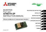

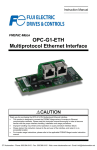
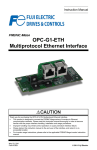

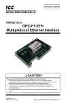
![XML.com: What is XSLT? [Aug. 16, 2000]](http://vs1.manualzilla.com/store/data/005688833_1-662f9c116837a2419b5ce07c9a17685b-150x150.png)