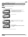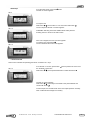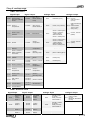
1
User manual CLIMATIC™ 50 ROOFTOP & AIRCOOLAIR Providing indoor climate comfort CL50-ROOFTOP-IOM-1107-E Climatic 50 Roof-Top & Aircoolair INSTALLATION OPERATING & MAINTENANCE MANUAL Ref : CL50-RoofTop-IOM-1107-E LENNOX have been providing environmental solutions since 1895, our range of Baltic TM rooftop continues to meet the standards that have made LENNOX a household name. Flexible design solutions to meet YOUR needs and uncompromising attention to detail. Engineered to last, simple to maintain and Quality that becomes a standard. Further Information on www.lennoxeurope.com. All the technical and technological information contained in this manual, including any drawing and technical descriptions provided by us, remain the property of Lennox and must not be used (except in operation of this product), reproduced, issued to or made available to third parts without the prior written agreement of Lennox. The technical informations and specifications contained in this manual are for reference only. The manufacturer reserves the right to modify these without warning and without obligation to modify equipment already sold. CLIMATIC™50 – IOM – Rooftops/ Aircoolair CL50-ROOFTOPS-IOM-1107-E 1 TABLE OF CONTENTS Page 3 4 8 10 INTRODUCTION CONNECTION CONFIGURATION SCHEDULING – CLOCK SETTING VENTILATION THERMOSTAT / HYGROSTAT – SET POINTS THERMOSTAT / HYGROSTAT – CONTROL PRINCIPLE FRESH AIR DAMPER - FREE-COOLING COMPRESSORS DEFROST – HEAT PUMP SUPPLEMENT OF HEATING (OPTION) CUSTOMIZED INPUT/OUTPUT 13 15 17 18 20 22 23 25 FAULT CODES Insufficient airflow Filters Clogged or Missing Ambient Temperature and Humidity, Outside Limits Blowing temperature, outside limits Overheating of Electrical Heating Elements Gas Burner Faults External Humidifier fault Hot Water Circulator Fault Fault in Real Time Clock Extension card fault (BE50) Faulty Probes and Sensors Blowing fan Condenser fans Water Condenser Faults Smoke Detector Compressors shut down on LP cut off Compressor shut down onHP cut off or electrical protection COMMUNICATION 28 29 30 31 32 33 34 34 35 35 36 37 38 39 40 41 42 43 MASTER/SLAVE BMS 43 45 CONFIGURING THE BM50 PLAN ADDRESS ALLOCATION OF DISPLAYS TO THE BM50 DC50 COMFORT & DM50 MULTI CUSTOMER DISPLAY DS50 SERVICE DISPLAY 46 47 48 53 DS50 MENU TREE CLIMATIC™50 INPUT/OUTPUT MAPPING 59 67 MODBUS, LONTALK ADRESS TABLES 70 CLIMATIC™50 – IOM – Rooftops/ Aircoolair CL50-ROOFTOPS-IOM-1107-E 2 INTRODUCTION CLIMATIC™50 The new generation of microprocessor based control, CLIMATICTM 50 may be fitted to the Lennox Roof-Top or AirCooler range. It inherits 20 years of technology and field operating experience from its predecessors the CLIMATICTM1 and CLIMATICTM 2. LENNOX has found the latest hardware technology available on the market place and developed a software specifically designed for Roof-Top and AirCooler applications, maximising the LENNOX units efficiency and performance. Compatibility This documentation is compatible with the programs Roof Top and AirCooler: • Ranges Baltic, Flexy I, Flexy II, FX and AC, starting from the version 20.0 Warning Any parameter modification should be carried out by trained and licensed competent technician. Before start-up or restart of a unit controlled by Climatic 50, it is mandatory to check adequacy between Climatic 50 and the unit with its options. • • 38xx menus for unit and options 39xx menux for communication In case of wrong parameters, I/O links could be incorrect and may create some operation problems for the units and ultimately breakdowns. Lennox cannot be held responsible for any claims on the units due to a wrong parameters sequence or a parameters modification carried out by non competent technicians. In this case, the warranty will be legally null and void. CLIMATIC™50 – IOM – Rooftops/ Aircoolair CL50-ROOFTOPS-IOM-1107-E 3 WIRING CONNECTIONS IMPORTANT WARNING Any wiring modification on the CLIMATIC 50 must be done by Lennox technician or employees having valid electrical qualification and authorisation. For any modification of wiring on the 24V supply or on 4-20mA sensor, check the polarity prior to apply the power. Wrong polarity may cause serious damage and destroy the Plan network. Lennox will not accept liability for damage caused by wrong power connection or any wiring modification done by people without valid training and qualifications. Any external connection with the unit, using 24Vac voltage should not exceed a length of more than 30m. It concerns external contacts connected to Climatic™50 logical inputs or humidifier control connection to the output 0-10v. Over 30 m, the installer must interface this information with relays or converters. In any case, the 24Vac control voltage must not be used to drive external function with Climatic™50 logical output WARNING: Separate as much as possible probes, displays, logical input cables from power cables with strong inductive load, in order to avoid possible electromagnetic perturbations . CONNECTION SENSORS AND PROBES External sensors or probes connection must be carried out with the following cable: - Cable length up to 20m: AWG22 (0.34 mm ²), 1 pair crossed with screen (2 pairs for CO2 sensor). - Cable length up to 50m: LiYCY-P (0.34 mm ²), 1 pair with general shield. (2 pairs for CO2 sensor). The cable length should not exceed 50m. For a better electromagnetic protection, Lennox recommends the use of LiYCY-P cable ROOM TEMPERATURE PROBE (NTC) The room temperature probe (- BT10) is connected to the Climatic™ main board BM50 50 entry B7 connector J6 (refer to the unit electrical wiring diagram). ROOM HUMIDITY SENSOR (0-20mA/Option) The room humidity sensor (- BH10) is connected to the Climatic™ extension board BE50 entry B1 connector J9 (refer to the unit electrical wiring diagram). ROOM AIR QUALITY SENSOR CO² (4-20mA / Option) The room air quality sensor (-BG10) is connected to Climatic™ main board BM50 entry B2 connector (refer to the unit electrical wiring diagram). DISPLAY DS50 The Display DS50 can be connected to the Climatic™ either on one of the RJ12 connectors located on the board DT50, or directly on the main board BM50 connector J10. Connection is carried out by the flat 1.5m cable delivered with this DS50. In any the case, Display DS50 cannot be remotely connected. In case of Master/Slave installation, one, and only one, display DS50 must be connected on the pLan bus. DISPLAY DC50 or DM50 (Remote CONNECTION) Warning: A wrong wiring of the display immediately damage it and/or the main board BM50. The optional DC50/DM50 is designed to be mounted on the wall. Fit the cable from the DT50 board through the back piece Fasten the back piece to the wall using the rounded head screws supplied in the packaging Connect the cable from the main board on the connector on the back of the DC50 display Fasten the front panel on the back piece using the flush head screws supplied Finally fit the click-on frame CLIMATIC™50 – IOM – Rooftops/ Aircoolair CL50-ROOFTOPS-IOM-1107-E 4 Display DC50 or DM50 is connected to the Climatic™ with the DT50 screw connector. Connection must be carried out by the following cable: - Cable length up to 300m: AWG22 (0.34 mm ²), 2 pairs crossed with screen. - Cable length up to 500m: LiYCY-P (0.34 mm ²), 2 pairs with general shield. The cable length should not exceed 500m. For a better electromagnetic protection, Lennox recommends the use of LiYCY-P cable CONNECTION ON DT50 REPARTITOR DT50 DC50 / DM50 3 + 4 GND 2 VL 1 1 2 3 4 Terminal connection board installation guide DT 50 The board is fitted with three "telephone" RJ12 plugs. Ensure the board is correctly connected. Standard connection is: BM50 on connector C DC50/DM50 on connector A or SC DS50 on connector B Jumpers: "Displays" are supplied directly by the Climatic board with 30Vdc. Take particular care at the path this 30V is taking when several boards are being used. J14 and J15 can switch on or off the direct current from the power supply: CLIMATIC™50 – IOM – Rooftops/ Aircoolair CL50-ROOFTOPS-IOM-1107-E 5 J14 and J15 set between1-2 : Connectors A, B, C and screw connector SC are in parallel. Power is supplied to all connectors. J14 and J15 set between2-3 : Connectors B and C are powered in parallel but connector A and screw connector SC are not. Displays connected to these ports will not be powered. If J14 and J15 are set in different positions the "terminal connection board" DT50 DOES NOT WORK and so the connected displays do not operate. DM50 and COMMUNICATION MASTER/SLAVE The intercard bus (pLan) is connected to Climatic™ on the J11 connector of board BM50. A star connection is not recommended, for an optimum operation it is advised to connect a maximum of two cables per unit. Connection must be carried out by the following cable: - Cable length up to 300m: AWG22 (0.34 mm ²), 2 pairs crossed with screen. - Cable length up to 500m: LiYCY-P (0.34 mm ²), 2 pairs with general shield. The cable length should not exceed 500m. For a better electromagnetic protection, Lennox recommends the use of LiYCY-P cable Warning: The power 24Vac of boards BM50 should not be connected to the earth CLIMATIC™50 – IOM – Rooftops/ Aircoolair CL50-ROOFTOPS-IOM-1107-E 6 BMS COMMUNICATION The communication bus is connected to Climatic™ Serial Card daughter board on the BM50. A star connection is not recommended, for an optimum operation it is advised to connect a maximum of two cables per unit. In case of RS485bus, a resistance of 120Ω 1/4W can be connected on the last unit between the terminals + and -. Connection must be carried out by the following cable: - Cable length up to 300m: AWG22 (0.34 mm ²), 2 pairs crossed with screen. - Cable length up to 1000m: LiYCY-P (0.34 mm ²), 2 pairs with general shield. The cable length should not exceed 1000m. For a better electromagnetic protection, Lennox recommends the use of LiYCY-P cable CLIMATIC™50 – IOM – Rooftops/ Aircoolair CL50-ROOFTOPS-IOM-1107-E 7 CONFIGURATION Function LENNOX© proposes a single software for the whole ranges of Roof-Top and Aircooler. For a first use, before any operation of the unit, Climatic™ must be set with parameters in accordance to the range, the size and the various options of the unit. Description The unit configuration is done with following menus (refer also to Menu Tree chapter): 3811 ! Unit range choice [BC] [BH] [BG] [BD] [BGN] [FC] [FC²] [FH] [FH²] [FG] [FG²] [FD] [FD²] [FGN] [FW] [FX] [ANC] [ANH] [NSR] Baltic, cooling only Baltic, reversible (heat pump) Baltic, gas Baltic, gas and reversible (heat pump) Baltic, gas, without compressor Flexy 1, cooling only Flexy 2, cooling only Flexy 1, reversible (heat pump) Flexy 2, reversible (heat pump) Flexy 1, gas Flexy 2, gas Flexy 1, gas and reversible (heat pump) Flexy 2, gas and reversible (heat pump) Flexy, gas, without compressor Flexy, cool water coil, without compressor Roof-Top with module 4 dampers Aircooler, cooling only Aircooler, reversible (heat pump Unit of nonstandard request 3812 ! Unit size choice BC BH BG BD BGN FC FC² FH FH² FG FG² FD FD² FGN BCK020NS BHK020NS BGK020SS BDK020SS BGN001S FCK085N FCM085N FHK085N FHM085N FGK085S FGM085S FDK085S FDM085S FGN002S BCK025NS BHK025NS BGK025SS BDK025SS BGN001H FCK100N FCM100N FHK100N FHM100N FGK100S FGM100S FDK100S FDM100S FGN003S BCK030NS BHK030NS BGK030SS BDK030SS FCK120N FCM120N FHK120N FHM120N FGK120S FGM120S FDK120S FDM120S FGN004S BCK035NS BHK035NS BGK035SS BDK035SS FCK140N FCM150N FHK140N FHM150N FGK140S FGM150S FDK140S FDM150S FGN005S BCK040NS BHK040NS BGK040SS BDK040SS FCK160N FCM170N FHK160N FHM170N FGK160S FGM170S FDK160S FDM170S FGN002H BCK045NS BHK045NS BGK045SS BDK045SS FCK190N FCM200N FHK190N FHM200N FGK190S FGM200S FDK190S FDM200S FGN003H BCK030ND BHK030ND BGK030SD BDK030SD FCM230N FHM230N FGK085H FGM230S FDK085H FDM230S FGN004H BCK035ND BHK035ND BGK035SD BDK035SD FGK100H FGM085H FDK100H FDM085H FGN005H BCK040ND BHK040ND BGK040SD BDK040SD FGK120H FGM100H FDK120H FDM100H BCK045ND BHK045ND BGK045SD BDK045SD FGK140H FGM120H FDK140H FDM120H BCK050ND BHK050ND BGK050SD BDK050SD FGK160H FGM150H FDK160H FDM150H BCK060ND BHK060ND BGK060SD BDK060SD FGK190H FGM170H FDK190H FDM170H BCK070ND BHK070ND BGK070SD BDK070SD FGM200H FDM200H BHK020HS BGK020HS BDK020HS FGM230H FDM230H BHK025HS BGK025HS BDK025HS BHK030HS BGK030HS BDK030HS BHK035HS BGK035HS BDK035HS BHK040HS BGK040HS BDK040HS BHK045HS BGK045HS BDK045HS BHK030HD BGK035HD BDK030HD BHK035HD BGK040HD BDK035HD BHK040HD BGK045HD BDK040HD BHK045HD BGK050HD BDK045HD BHK050HD BGK060HD BDK050HD BHK060HD BGK030HD BDK060HD BHK070HD BGK070HD BDK070HD 3813 ! Activation of the Controls humidity option 3814 ! Activation of the High Efficiency Main fan and/or Variable speed transmission option, 3815 ! Activation of the External Thermostat Temperature Control option, 3821 ! Choice of the type of sensor or probe on the refrigeration circuit [No] No probe or sensor of installed on the circuits CLIMATIC™50 – IOM – Rooftops/ Aircoolair FWN FWN002S FWN003S FWN004S FWN005S FWN002H FWN003H FWN004H FWN005H FX FXK025N FXK030N FXK035N FXK040N FXK055N FXK070N FXK085N FXK100N FXK110N FXK140N FXK170N CL50-ROOFTOPS-IOM-1107-E ANC ANCM022E ANCM026E ANCM032E ANCM038E ANCM043E ANCM052D ANCM064D ANCM076D ANCM086D ANCM112D ANCM128D ANCM152D ANH ANHM022E ANHM026E ANHM032E ANHM038E ANHM043E ANHM052D ANHM064D ANHM076D ANHM086D ANHM112D ANHM128D ANHM152D 8 [NTC] Temperature probe `NTC' on the sticks of the coils [0-5V] Transmitter of pressure `Ratiométrique' on the circuits [4-20mA] Transmitter of pressure `4-20mA ' on the circuits 3822 ! Activation of the Low Ambient Kit option, 3823 ! Unit with water condensation 3824 ! Activation of the Alternate Defrost option for the Flexy1 range sizes 85 and 100 3831 ! Choice of the auxiliary heating type. [No] No auxillary heating [Hot W/Coil] Hot water coil [Gas 2] Gas, 1 slope with 2 steps [Gas 4] Gas, 2 slopes with 2 steps [Gas 2 Pro.] Gas, 1 modulating slope [Gas 4 Pro.] Gas, 2 modulating slope [ElecH. Ste] Electric heaters, without Triac modulation. [ElecH. Pro] Electric heaters, with Triac, Positioned after the refrigerant coil [ElecH. Mix] Electric heaters, with Triac, Positioned before the refrigerant coil 3711 ! Choice of the type of gas valves control board. [BG50] Board BG50 [EF49] Board EF49 [EF48] Board EF48 [EF45] Board EF45 [MMI No] Block gas with output fault in normally open [MMI Nc] Block gas with output fault in normally closed 3832 ! Choice of the type air mixing box [No] No fresh air [100%] All fresh air [0%-100%] Economiser proportional [0%-50%] Economiser proportional, limitation to 50% of opening 3517 ! Activation of the air heat recovery option, 3833 ! Choice of the type of air flow sensor [No] No option [500pa] Sensor, 0 to 500 pa [1000pa] Sensor, 0 to 1000 pa 3834 ! Choice of the air quality sensor [No] No option [0-2000] Sensor, 0 to 2000 ppm [350-2000] Sensor, 350 to 2000 ppm (Carel© brand sensor) CLIMATIC™50 – IOM – Rooftops/ Aircoolair CL50-ROOFTOPS-IOM-1107-E 9 SCHEDULING – CLOCK SETTING CLOCK SETTING Function Climatic™ has a real time clock board, allowing dates and hours functionalities (weekly Program, event recording,…). Description Menus 3121 to 3125 give the possibility of setting the internal clock. The day of the week is calculated by Climatic™. For the countries of the Euro a device allows the automatic swing of the hour summer in hour winter and vice versa. This functionality can be cancelled by menu 3126. 3121 ! Hour. 3122 ! Minute. 3123 ! Day of the month. 3124 ! Month. 3125 ! Year. 3126 ! Enable automatic switch summer time / winter time. SCHEDULING Function Controlling operation of the unit according to the time and day Description CLIMATICTM 50 can handle 4 time zones over the 7 days of the week: • • • • • Zone unoccupied « Night » Zone A « Day A » Zone B « Day B » Zone C « Day C » Starting time (hours and minutes) of each of these zones for each days of the week, can be set using menus 3211 to 3214, (press ‘Prg’ key to change day). Each set point integrates the hour and minute’s adjustment, thus a value of 8.3 equal 8.30 a.m. 3211 ! Hour, minute of the night starting time (unoccupied) 3212 ! Hour, minute of the “day A” starting time 3213 ! Hour, minute of the “day B” starting time 3214 ! Hour, minute of “day C” starting time 8h00 Monday Unoccupied 12h00 Z :A 13h50 Z :B 20h30 Z :C 22h00 Unoccupied Tuesday Wednesday Thursday Friday Saturday Sunday CLIMATIC™50 – IOM – Rooftops/ Aircoolair CL50-ROOFTOPS-IOM-1107-E 10 For each time zone, the set following set points following can be modified: LIST SET POINT BY ZONE Code DISPLAY CONFORT DISPLAY MAINTENANCE Ambient temperature Set point average 3311 Yes Yes Set point dynamic 3321 Yes Yes Cooling Set point 3322 Yes Heating Set point 3323 Yes Priority of heating 3324 Yes Enable 3331 Yes Priority of heating 3332 Yes 3312 Yes Reheating of Fresh Air Fresh Air Set point Humidity Dehumidification 3341 Yes Humidification 3342 Yes Free Cooling 3353 Yes Fresh Air by CO² 3354 Yes Refrigeration by compressor 3355 Yes Heating by compressor 3356 Yes Auxiliary heating 3357 Yes Authorisation Humidity Control 3358 Yes Low noise level 3359 Yes Fan, Activate 3351 Yes Fan, Activate, in dead zone 3352 Yes Minimum fresh air (%) 3353 Other Yes Yes Yes Yes Programming Beginning of zone; each day Start Uno 3211 Yes Yes Start z.A 3212 Yes Yes Start z.B 3213 Yes Yes Start z.C 3214 Yes Yes With the DS50, for each set point, to press on the key `Prg' to change the periods and to validate the good set point for the good zone. Note: “Monday” is considered as the first day of the week for programming the CLIMATIC™50. Factory settings: “Day A” activated from Monday to Saturday 6h!22h Night mode (unoccupied) for the remaining of time, Sunday included CLIMATIC™50 – IOM – Rooftops/ Aircoolair CL50-ROOFTOPS-IOM-1107-E 11 ANTICIPATION Function This allows an anticipated start-up in the morning depending on the outdoor temperature. Description This function only works for zone A, and allow the machine to move from unoccupied zone to zone A earlier if the outdoor temperature is under a certain value. Use this function to anticipate the heating start-up during cool days. Hour of starting zone A 7h30 Air Temp. Outside 8h00 0°C This can be adjusted with set point 3221 and 3222. 3°C 3221 ! bottom of the slope (°C), Anticipation starting point 3222 ! Slope in Minutes of anticipation per degrees Example: Unit with Day A starting at 8.00 am; 3221 set to 3°C and 3222 set to 10 mn/°C; If the outside temperature is 0°C, then Day A will start at 7.30 a.m. CLIMATIC™50 – IOM – Rooftops/ Aircoolair CL50-ROOFTOPS-IOM-1107-E 12 VENTILATION ON / OFF (Start & Stop) Function In general, the unit is considered in operation if its supply fan is in operation. But, according to the set points, the fan may stop in the temperature control dead zone. Description To allow the operation of the unit it is necessary that set point 3111 is set to `On' and that the BM50 logical input ID7 on the J5 connector is closed. The 3111 set point adjustment is available on the DC/DM50 with the ON/OFF functionality. For each scheduled zone defined in Climatic™50, it is possible to set the start/stop state. This functionality allows the unit to stop during a period of time in the day. When the Room temperature is within the regulation dead zone, for each scheduled zone defined in the Climatic™50 it is possible run or stop the fan 3111 ! Main On/Off. 3351 ! On/Off, adjustment by zone. 3352 ! On/Off in the temperature control dead zones, adjustment by zone. STAGGING START Function After a power shut-down, you may get the units to restart gradually in order to avoid overloading issues. Description The units do not need to be connected; they must simply have different pLan addresses, (see BM50 pLan address configuration). This will enable them to restart (10 x their address number) seconds after the resumption of the power. Example: If a unit carries the address n°3, it will start again 30s (3 X 10 seconds) after the resumption of the power. HIGH EFFICIENCY FANS or/and WITH VARIABLE SPEED TRANSMISSION Function The supply fan variable speed option allows two functionalities; Progressive start or stop (used for the textile duct inflation) The speed reduction, in temperature control dead zone, in order to bring only the necessary fresh air quantity. Description The supply fan speed is originally fixed by the set point 3422. The speed entered in this set point corresponds to nominal air flow of the installation. This set point can only be adjusted on site. Progressive Start / Stop If set point 3423 is activated; During fan start up, for 30s, the speed is fixed by the threshold set point 3421. Then during the next 30s the fan accelerates gradually to reach the speed fixed in the set point 3422. During the fan stop, the speed gradually reduces to stop completely in 1 minute. CLIMATIC™50 – IOM – Rooftops/ Aircoolair CL50-ROOFTOPS-IOM-1107-E 13 Dead zone reduction speed in If set point 3424 is activated; When the room temperature is in the regulation dead zone of regulation (no heating, nor cooling), the speed of the fan is fixed by the set point 3421 and the fresh air damper is opened at 100%. If the minimum speed brings a fresh air quantity higher than the defined threshold, the fresh air damper will close proportionally to reach the desired value. 3421 ! Minimum fan speed threshold (%). 3422 ! Maximum fan speed threshold (%). 3423 ! Activation of progressive Start functionality. 3424 ! Activation of dead zone speed reduction functionality. EXHAUST FANS Function From one to three exhaust fans can be controlled. The start and the stop of these fans depend on the opening of the fresh air damper. Description The fans are activated if the fresh air damper opening percentage is higher than the thresholds fixed by the set points. 3431 ! Fresh air damper threshold, activation of the 1st fan (%). nd 3432 ! Fresh air damper threshold, activation of the 2 fan (%). 3433 ! Fresh air damper threshold, activation of the 3rd fan (%). CLIMATIC™50 – IOM – Rooftops/ Aircoolair CL50-ROOFTOPS-IOM-1107-E 14 THERMOSTAT / HYGROSTAT – Set points SET POINTS, TEMPERATURE Function Climatic™ is programmed in order to maintain a temperature as comfortable as possible with the most economic usage of the unit. Description If this set point is modified, it has priority on the 2 thresholds, but the dead zone range remains defined by the difference between the 2 thresholds. If the Thresholds 3322 and 3323 are modified, set point 3311 is automatically calculated to their average value. Cooling Threshold (3322) Dead zone The room temperature is maintained between a minimum threshold - corresponding to the heating point - and a maximum threshold - corresponding to the cooling point. The regulation “dead zone” is defined between these two thresholds. In order to be user friendly, one temperature set point is used. This set point is in the middle of the dead zone. ∆ Customer set point (3311) ∆ Heating Threshold (3323) Ambient Temp °C Cooling Mode Heating Mode 3311 ! Customer temperature set point (°C), adjustment by zone. 3322 ! Cooling temperature threshold (°C), adjustment by zone. 3323 ! Heating temperature threshold (°C), adjustment by zone. Set point modification by an external signal The set point can be remotely modified with a signal 4-20mA (see CUSTOMIZED INPUT / OUTPUT) For a 4 mA signal the temperature set point is decreased by 5°k For a 20 mA signal the temperature set point is increased by 5°k A linear rule is applied between the two signals. DYNAMIC SET POINT Function This function allows to obtain a proportional shift of the cooling threshold according to the outside temperature. Description The cooling threshold starts to increase once the outside air temperature is over the cooling threshold plus the value of the dynamic set point. If you don’t wish to use this function, allot to the option dynamic set point the value 99.9°c Example: If the cooling threshold is equal to 25°C and that the dynamic set point is equal to 6K The cooling threshold drift will start for an outside temperature of 31°C (25°C + 6K) and then the threshold will follow the outside temperature evolution keeping a 6K difference. 3321 ! Dynamic set point (K), adjustment by zone. CLIMATIC™50 – IOM – Rooftops/ Aircoolair CL50-ROOFTOPS-IOM-1107-E 15 FRESH AIR REHEATING SET POINT Function Climatic™ may be set to maintain a comfortable blowing temperature, by compensating the cold contribution of fresh air in winter. Description If this function is activated: • If the room temperature is in regulation dead zone, or heating mode, the blowing air regulation rule will maintain a blowing temperature at least equivalent to the heating threshold. • If the room temperature is in cooling mode, the minimum blowing temperature will be equal to the safety low limit threshold plus 2K. 3331 ! Activation of the control of reheating of the fresh air, adjustment per zone. HUMIDITY SET POINT (option) Function The relative humidity of room is maintained between two thresholds, a minimum threshold corresponding to the point of humidification and a maximum threshold corresponding to the point of dehumidification. Description Dehumidification It is ensured by the compressors in cooling mode. It is active in the dead zone and cold mode of room temperature control. Climatic™ gives priority to the temperature. To ensure a complement of heating, the fresh air reheating set point must be activated. Humidification A signal 0-10v is generated proportionally to the regulation request. 3341 ! Dehumidification threshold - Relative humidity (%hr), adjustment by zone. 3342 ! Humidification threshold - Relative humidity (%Hr), adjustment by zone. 3358 ! Activation or inhibition, humidity control. CLIMATIC™50 – IOM – Rooftops/ Aircoolair CL50-ROOFTOPS-IOM-1107-E 16 THERMOSTAT / HYGROSTAT – Control principle Function Adjust and hold the room air temperature or humidity as close as possible to the set point, by controlling the number of compressor stages depending on the thermal load of the system. Description CLIMATICTM50 control constantly calculates the required capacity to reach the temperature set point. This variable is called “CAPACITY FACTOR” (CF) and its value can vary from 0 to 100%. It is directly linked to the number of control stages of the unit. Thus for a unit with 4 stages of regulation, the CF will start and stop a stage with the following values: 0-25-50-75-100. It then evolves following the principles detailed in the diagram below (case of a cooler): + 2°K CF INCREASES (Start more Capacity Stages) CF FROZEN + 1°K Difference between the Room Temperature and the 0°K set point - 1°K CF DECREASES (Removes Capacity Stages) CF FROZEN - 2°K FAST SLOW Room Temperature Change rate SLOW FAST In order to anticipate, the reference point is recalculated each time the difference between air temperature and set point reach a minimum or a maximum. The rate of change of the Capacity Factor (CF) is determined by another parameter called “REACTIVTY” and which value is in: % of CF / °C (Diff vs Set point) / min 3361 ! REACTIVITY for the cooling mode. 3362 ! REACTIVITY for the heating mode. 3363 ! REACTIVITY for the fresh air reheating mode For the option of control humidity 3364 ! REACTIVITY for the dehumidification mode. 3365 ! REACTIVITY for the humidification mode. Permutation, Cold or Heat Mode (Change-Over ; optional) The choice of the operating mode in cooling or heating is automatically carried out according to the room temperature and the temperature set points adjustment. Meanwhile as an option, using free contacts on parametric inputs, it is possible to disable one mode or another. (see Customized Input / Output (BE.50)) • With a free contact on [Sw Dis.Cool] The contact closing will disable the cooling mode. • With a free contact on [Sw Dis.Heat] The contact closing will disable the heating mode. CLIMATIC™50 – IOM – Rooftops/ Aircoolair CL50-ROOFTOPS-IOM-1107-E 17 FRESH AIR DAMPER - Free-Cooling Function Ensure a minimum fresh air introduction into the room and/or a free-cooling, thus reducing electric consumption. Description MINIMUM FRESH AIR Adjustment by set point The fresh air rate is adjustable by set point. 3312 ! Minimum opening of the fresh air damper, %, adjustment by zone. Adjustment by free contacts (optional) With the customized free contacts, the fresh air rate can be adjusted. (see Customized Input / Output (BE.50)) • With a free contact on [0% F.A.]) The contact closing will close completely the damper. • With a free contact on [100% F.A.] The contact closing will open completely the damper. • With a free contact on [10% F.A.], [20% F.A.], [30% F.A.], [40% F.A.] or [50% F.A.] The contact closing will open the damper to the mentioned rate. If several contacts are customized with this functionality, the air damper will open according to the sum value of all closed contacts. In any case, the minimum fresh air rate will be fixed according to the highest value between the set point and the request by contacts. Adjustment by external signal (optional) The minimum fresh air can be remotely modified by a signal 4-20mA. (See Customized Input / Output (BE.50)) For a signal of 4 mA applied on [F.A Offset] the threshold is set to 0% For a signal of 20 mA applied on [F.A Offset] the threshold is set to 100% A linear rule is applied between the two limits. Air quality sensor, CO² (optional) If a CO² sensor is connected to the unit, the minimum value of fresh air is calculated according to the CO² rate. This functionality can be activated, or not, within the 4 day zones. Two opening mode may be selected: • Fresh air damper opening between 0% and the minimum fresh air set point [0-Min] Minimum Fresh Air 0 • Set point 3513 Set point 3514 2000 ppm Fresh air damper opening between the minimum fresh air set point and the maximum fresh air set point. [Min-max] Set point 3512 Minimum Fresf Air 0 Set point 3513 CLIMATIC™50 – IOM – Rooftops/ Aircoolair Set point 3514 2000 ppm CL50-ROOFTOPS-IOM-1107-E 18 2132 ! CO² rate measured value of the (ppm). 3354 ! CO² function authorization, adjustment by zone. 3515 ! CO² function mode [0-Min], [Min-Max]. 3513 ! CO² rate (ppm), threshold until which the 0% or the minimum fresh air is maintained. 3514 ! CO² rate (ppm), threshold from which the minimum fresh air or the 100% is used. 3512 ! Maximum fresh air damper opening. Fresh air damper Calibration The real fresh air volume introduced into the system is not always proportional to the damper opening percentage. That is particularly true when the return air duct system is sized to give excessive pressure losses. It results with excessive fresh air input, and thus with an increase of the system exploitation costs. From now on, it is possible to calibrate the fresh air using three temperature probes: one in the blowing section, another in the return air and the last one in the outdoor temperature. Using these three probes, Climatic™50 calculates and memorizes the exact percentage of fresh air for each position of the damper. Blowing T° = Return T° x %Return Air + Fresh air T° x %Fresh Air This adjustment sequence takes place periodically when all heating and cooling elements are off. 3516 ! Fresh air damper calibration authorization. FREE COOLING From a room temperature need (Capacity Factor) the damper opens according to a proportional rule on the blowing temperature. 0% need = Minimum fresh air. 100% need = low limit threshold (3373) + 2K The user may choose to limit the fresh air damper operation with contacts or set points modification (see minimum fresh air § above). The outdoor temperature or humidity value may also limit the opening. Outdoor temperature The Free-Cooling is stopped if the outside temperature is higher than the return or room temperature. The Free-Cooling is stopped if the outside temperature is lower or higher than the threshold defined in set point (3511). Free cooling is forbidden on high limit for a set point adjustment over +20.0°c. Free cooling is forbidden on low limit for a set point adjustment lower than +20.0°c. Outdoor humidity (optional) If humidity control option is selected, the Free-cooling is stopped if the external absolute humidity (water weight) is higher than the indoor absolute humidity. Set point The Free-Cooling is stopped if the set point (3353) is No Free contact (optional) Stop of Free-Cooling by closing customized free contacts. (See minimum fresh air § above) [0% A.N.] = the register of air is completely closed. [100% A.N.] = the register of air is completely open. 3353 ! Economiser functionauthorization, adjustment by zone. 3373 ! Low limit blowing temperature threshold. 3511 ! Outdoor temperature threshold for authorization of the economiser function. 3512 ! Maximum fresh air damper opening CLIMATIC™50 – IOM – Rooftops/ Aircoolair CL50-ROOFTOPS-IOM-1107-E 19 COMPRESSORS Function From a room temperature need (Capacity Factor) the compressors are started and stopped with a determined sequence in order to minimize the anti short cycle protection effect and to equalize the operating time. Description Compressors Start/Stop sequences. This sequence is set by the memorized compressor operating time and it also includes the other compressors back-up function, if they are not available. For circuits with tandem compressors, it is possible to favour the unit performance, COP, rather than the compressor operating time balance (3642). The compressor starts if all the following conditions are satisfied: • The unit, the compressor and the circuit do not have major faults. • The control requires the starting of the compressor. • The compressor has the lowest operating time among the stand by compressors. • The compressor has not been brought into service for at least 6 minutes. Every compressor state can be checked on the following menus: 2512, 2522, 2532…, 2562 To check the operating time of each compressor use menus: 2519, 2529….2569 To reset an operating time counter, put the DS50 cursor on the line and press the key `Enter' during 20 seconds. Compressor operation authorization. The user may choose to limit the operation of the compressors by using contacts or set points modification. Outdoor temperature Cooling mode Stop of all compressors if the outdoor temperature is lower than the threshold (3612) Stop of 50% of the compressors if the outdoor temperature is lower than the threshold (3611) Note: if the option `Low Ambient Kit' is activated (3822) these two functionalities are disabled. Heating mode (Heat pump) Stop of all compressors if the outdoor temperature is higher than the threshold (3613) Set points Stop of one or several compressors if the compressor number is not displayed in the address (3641) Cooling mode Stop of all compressors if the instruction (3355) is set to [No] Limitation to 50% of the compressors if the instruction (3359) is set to [Yes] Immediate stop of 50% of the compressors if the instruction (3643) is set to [Yes] Heating mode (Heat pump) Stop of all the compressors if the instruction (3356) is set to [No] Note: Address 3355 and 3356 can be set differently for zones A, B, C, Uno or BMS Note: The address 3359 can be set differently for zones Uno or BMS Free contacts (Optional - See Customized Input / Output (BE.50)) Stop of one or several compressors if the compressor number is not displayed in the address (3641) Stop of 50% of the compressors if the contact [Dis. 50%Cp] is close. Stop of all the compressors if the contact [Dis. Cp/Ah] or [Dis. Comp] is close. High pressure offloading (FLEXY 2 tandem only) With tandem compressors, it is possible to reduce the circuit capacity by stopping one of the two compressors before the high pressure reaches its limits in order to keep a partial capacity with high outdoor temperature. If the condensing pressure is higher than 40b and continuously increases with all the fans in operation at full speed, 1 compressor of the considered circuit is stopped. CLIMATIC™50 – IOM – Rooftops/ Aircoolair CL50-ROOFTOPS-IOM-1107-E 20 3355 ! Compressors authorization in cooling mode, adjustment by zone. 3356 ! Compressors authorization in heating mode, adjustment by zone. 3359 ! Limitation to 50% of the compressors, in Unoccupation and BMS mode. 3611 ! Low outdoor temperature threshold for limitation to 50% of the compressors, in cooling mode 3612 ! Low outdoor temperature threshold for stopping all compressors in cooling mode. 3613 ! High outdoor temperature threshold for stopping all compressors in heating mode.. 3641 ! Compressors authorization. 3642 ! Rotation mode choice. 3643 ! Off loading of 50% of the compressors. CLIMATIC™50 – IOM – Rooftops/ Aircoolair CL50-ROOFTOPS-IOM-1107-E 21 DEFROST – Heat Pump Function Avoid the evaporator icing (external coil) in heat pump operation in winter time. Description To avoid the icing of the external air exchanger in winter operation, it is necessary to reverse the refrigerant cycle on a regular basis to de-ice by heating the exchanger. The defrost is activated when the air temperature is under a set point (3422) When defrost is demanded, the sequence is as following: 1. 2. 3. 4. 5. 6. 7. Pre-heating of supplementary heating elements during 1 minute (Option) Stop compressors and fans Reverse 4 way valve Start compressors. When the fans are started several times (3625) or if compressors are in operation for more than 6 minutes, stop the compressors. Reverse 4 way valve End of defrost Two different type of Defrost demand are possible. • Dynamic defrost (set point 3621 = Dynamic) • Cycling defrost (set point 3621 = Cyclic) Cycling defrost The unit will start a cyclic defrost under a regular period of time (instruction 3624) Dynamic defrost This allows the unit to start the defrost cycle only when required. This is achieved through the measurement of the temperature difference between the coil and the outdoor. The defrost will be initiated shortly after the Climatic50 has located the largest gradient in the curve. Temperature difference between coil and outdoor Coil clean Coil freezing Coil frozen Defrost cycle start Highest gradient Time 3621 ! Defrost mode. 3622 ! Outside air temperature under which the defrost cycle is activated. 3623 ! LP temperature under which the defrost cycle is activated for the cyclic mode and defrost cycle activation sensibility for the dynamic mode (standard ratio between dry coil ∆T and iced coil ∆T) . 3624 ! Minimum compressors operating time between 2 defrosts 3625 ! Number of fans Restart operations according to the pressure. CLIMATIC™50 – IOM – Rooftops/ Aircoolair CL50-ROOFTOPS-IOM-1107-E 22 SUPPLEMENT OF HEATING (Option) Fonction Units may be equipped with 3 types of supplementary heating: Gas (BG, FG et BD, FD) Hot water coils (BC, FC et BH, FH) Electric heaters (BC, FC et BH, FH) From a room temperature need (Capacity Factor) the supplement of heating stages are started and stopped with a predetermined order. Description Operation priority, Compressors / Additional heating From factory setting, in heat pump mode, Climatic™ starts compressors first and then if necessary, starts additional heating. This sequence may be reversed with set points for the ambient temperature regulation and for fresh air pre-heating. 3324 ! Priority inversion from compressors to supplementary heating, air temperature regulation, adjustment by zone. 3332 ! Priority inversion from compressors to supplementary heating, fresh air regulation, adjustment by zone. Operation authorization The user may choose to limit the operation of the compressors by using contacts or set points modification. Set points Stop of additional heating if the set point (3357) is set tp ‘No’. Note: The address (3357) can be set differently for zones A, B, C, Ino ou GTC Contact Stop of the gaz module if the free contacts [Dis. Cp/Ah] or [Dis. AuxH.] are closed. (See Customized Input / Output (BE.50)). 3357 ! Supplementary heating authorization adjustment by zone. ELECTRICAL HEATERS Electrical heaters are stopped if the outside temperature is above a threshold in set point (3721). The capacity of electrical heaters piloted by a Triac may be limited. The set point (3723) fixes the maximum threshold. For electrical heaters piloted by a Triac and positioned before the coil, if the mixing air temperature is below the threshold in set point (3722), the electrical heaters are activated to 100%. For electrical heaters piloted by a Triac and positioned after the coil, if the blowing air temperature is below the threshold in set point (3722), the electrical heaters are activated to 100%. Pour les résistances électrique pilotées par Triac et positionnées après la batterie de détente directe ; si la température de soufflage est inférieure au seuil de la consigne 3722 les résistances sont activées à 100% 3721 ! Outside air temperature threshold for electrical heaters authorization. 3722 ! Minimum temperature threshold, Triac. 3723 ! Maximum capacity threshold, Triac. HOT WATER Protection against freezing with minimum water flow. If the outside air temperature is below the set point (3331), the valve will open to a minimum fixed in the threshold (3332). Freezing fault In general, in case of detection of hot water coil icing, the valve will open to 100%. Due to certain hydraulic network, pumps or tracing, the coil protection is done by closing the valve. This can be activated with the set point 3733. 3731 ! Outside air temperature threshold for authorization, minimum water flow. 3732 ! Valve opening threshold , minimum water flow. 3733 ! Valve action in case of freezing fault. CLIMATIC™50 – IOM – Rooftops/ Aircoolair CL50-ROOFTOPS-IOM-1107-E 23 HOT WATER CIRCULATOR The Climatic may drive a circulator for the hot water hydraulic circuit. The activation mode of the circulator must be determined according to the circuit. 3741 ! Circulator operating mode. [No] No circulator [Frost.Al.] Circulator activation in case of freezing fault [Start Heat.] Circulator activation in heating mode for air temperature regulation. [Started] Circulator activation as soon as the blowing fan is activated. CLIMATIC™50 – IOM – Rooftops/ Aircoolair CL50-ROOFTOPS-IOM-1107-E 24 CUSTOMIZED INPUT/OUTPUT Function On the BM.50 card and with the optional expansion board BE.50, it is possible to customize some input / output for remote control of the unit. So it is possible to customize • 5 digital outputs NC or NO set up with parameters 3841, 3842, 3843 and 3845 • 6 digitals inputs set up by parameters 3851, 3852, 3853 and 3854 • 4 analogical inputs (4-20mA or Lennox NTC temperature probe), set up with parameters 3861, 3862, 3863 et 3864 Description Il est possible de paramétrer les fonctions suivantes : SORTIE DIGITALE NC ou NO - CONTACTS SECS Following information could be recovered from each contact : [Not Used.] [Filter Al.] [Blower Al.] [Comp. Al.] [Gas Al] [ElecH. Al] [Frost. Al] [Smoke. Al.] [Heat. Mode] [Humidif.] [Z:A] [Z:B] [Z:C] [Uno] [Bms] [LibrFree] [Exhaust 1] [Exhaust 2] [Exhaust 3] No contact Filter fault Blowing fan fault Compressor fault Gaz fault Electrical heater fault Alarm, freezing risk Smoke detector alarm Heating mode Humidifier pilote Unit operating Mode A Unit operating Mode B Unit operating Mode C Unit operating Mode Inoccupied Unit operating Mode BMS Free for BMS acting Drive exhaust fan n°1 Drive exhaust fan n°2 Drive exhaust fan n°3 3841 ! Setting of connector BM50-J17-N12. 3842 ! Setting of connector BE50-J5-N1. 3843 ! Setting of connector BE50-J6-N2. 3844 ! Setting of connector BE50-J7-N3. 3845 ! Setting of connector BE50-J8-N4. ENTREE DIGITALE 24V AC ou DC following orders can be sent on each contact: [Not Used] No contact [Sw Unoc.] Force Unoccupied Mode [Dis. Cp/AH] Stop of all compressors and auxillary heating [Dis. Comp. ] Stop of all compressors [Dis. 50%Cp] Immediate stop of 50% of the compressors [Dis. AuxH.] Stop of supplementary heating [Sw Dis.Cool] Cancellation of cooling mode [Sw Dis.Heat] Cancellation of heating mode [State Humi] Humidifier fault input [0% F.A. ] Force 0% fresh air [10% F.A.] Add 10% fresh air [20% F.A. ] Add 20% fresh air [30% F.A.] Add 30% fresh air [40% F.A.] Add 40% fresh air [50% F.A.] Add 50% fresh air [100% F.A.] Force 100% fresh air [Low Speed] Force low speed ventilation [Free] Free for BMS system information. CLIMATIC™50 – IOM – Rooftops/ Aircoolair CL50-ROOFTOPS-IOM-1107-E 25 3851 ! Setting of connector BM50-J8-ID13. 3852 ! Setting of connector BM50-J8-ID14. 3853 ! Setting of connector BE50-J4-ID1. 3854 ! Setting of connector BE50-J4-ID2. 3855 ! Setting of connector BE50-J4-ID3. 3856 ! Setting of connector BE50-J4-ID4. ENTREE ANALOGIQUE It is possible to make the following actions: [Not Used] Not used [S.P Offset] Ambient temperature set point offset – 4-20mA signal. [F.A Offset] Minimum fresh air set point – 4-20mA signal. [Weather T.] Entry for a Meteo temperature sensor [Weather H.] Entry for a meteo humidity sensor [Free NTC] Free temperature probe connection [Free Hr.] Free relative humidity sensor connection Ambient temperature set point offset – 4-20mA signal: The 4-20mA signal sent to the unit is linearly converted using a -5K to +5K range of temperature set point. For example: for a unit set point of 20°C A 4mA signal will give a 15°C unit temperature set point A 20mA signal will give a 20°C unit temperature set point A 20mA signal will give a 25°C unit temperature set point Minimum fresh air set point – 4-20mA signal: The 4-20mA signal sent to the unit is linearly converted to a 0% - 100% fresh air damper opening request. Entry for a Meteo temperature sensor: The 4-20mA signal sent to the unit is linearly converted using a -40°C to +80°C range, this measure will replace the one given by the unit sensor. Entrée d’une sonde météo, en humidité : The 4-20mA signal sent to the unit is linearly converted using a 0% to 100% range, , this measure will replace the one given by the unit sensor. Free temperature probe connection: Lennox NTC sensor. The measured value will be displayed on following addresses 2161, 2162, 2163 or 2164. Free relative humidity sensor connection: The 4-20 mA signal sent to the unit is linearly converted using a 0% to 100% range. The measured value will be displayed on following addresses 2165, 2166, 2167 or 2168. 3861 ! Setting of connector BE50-J9-B1. 3862 ! Setting of connector BE50-J9-B2. 3863 ! Setting of connector BE50-J10-B3. 3864 ! Setting of connector BE50-J10-B4. CLIMATIC™50 – IOM – Rooftops/ Aircoolair CL50-ROOFTOPS-IOM-1107-E 26 ERROR CODES 001 004 005 011 012 013 014 015 022 023 031 032 033 041 070 071 081 082 083 084 085 086 087 088 091 092 093 094 095 096 097 098 099 111 115 117 121 125 127 131 135 137 141 145 147 "Airflow" Filters, Clogged up Filters, Missing Electric heating elements High Temperature, Blowing Low Temperature, Ambient Gas burner, 1 Gas burner, 2 Low Temperature, Blowing High Temperature, Ambient Humidifier Low Humidity, Ambient High Humidity, Ambient Pump Clock card BE50 Temperature sensor, Ambient Humidity sensor, Ambient Temperature probe, Outside Humidity sensor, Outside Temperature probe, Blower Circuit 1, Temperature sensor, Water condenser Outlet Circuit 2, Temperature sensor, Water condenser Outlet Temperature sensor, return or Mixing air Treatment Fan Circuit 1, Condenser fan Circuit 2, Condenser fan Circuit 3, Condenser fan Circuit 4, Condenser fan Low temperature, Water Condenser High temperature, Water Condenser Flow rate, water condenser Smoke detector Circuit 1, Probe or Sensor Circuit 1, High pressure or electrical protection Circuit 1, Low pressure Circuit 2, Probe or Sensor Circuit 2, High pressure or electrical protection Circuit 2, Low pressure Circuit 3, Probe or Sensor Circuit 3, High pressure or electrical protection Circuit 3, Low pressure Circuit 4, Probe or Sensor Circuit 4, High pressure or electrical protection Circuit 4, Low pressure CLIMATIC™50 – IOM – Rooftops/ Aircoolair CL50-ROOFTOPS-IOM-1107-E 27 Insufficient airflow Error code: 001 Description The pressure differential between the treatment unit and the filters is small although the fan has been running for more than 3 minutes. ∆p < safety threshold for more than 20 seconds 2131 ! ∆p. 3411 ! Safety threshold Action " Immediate shutdown of the complete unit. " Fault signalling. If a DS50 is connected to the unit; Memorisation and display of all faults Otherwise; Memorisation and display of the 3rd daily fault only. Reset The unit restarts automatically 2 minutes after making safe. The fault will no longer be reset automatically after 3 cut outs in the same day and must be reset manually. Note: The fault counter is cleared and reset every day at 11 am, provided the maximum number of faults has not been reached. Possible causes Air system obstructed or closed Broken belts Problem with the fan wiring Problem with the pressure transmitter wiring Incorrect setting of the safety threshold CLIMATIC™50 – IOM – Rooftops/ Aircoolair Solving the problem Check the system Replace the belts Check the connections Check the connections Check the settings CL50-ROOFTOPS-IOM-1107-E 28 Filters Clogged or Missing Error code: 004, 005 Description The pressure differential between the treatment unit and the filters is small although the fan has been running for more than 3 minutes. Filters missing: ∆p < safety threshold for more than 1 minute Clogged filters: ∆p > safety threshold for more than 1 minute 2131 ! ∆p. 3412 ! Safety threshold, filters missing. 3413 ! Safety threshold, blocked filters. Action " No safety. " Fault signalling. Memorisation is displayed " Display of fault. 004, Filters clogged 005, filters missing Reset Automatic reset of the fault as soon as the pressure returns to the authorized operating range. Possible causes Filters removed and not replaced Filters clogged Problem with the pressure transmitter wiring Incorrect setting of the safety thresholds CLIMATIC™50 – IOM – Rooftops/ Aircoolair Solving the problem Fit new filters Clean or replace the filters Check the connections Check the settings CL50-ROOFTOPS-IOM-1107-E 29 Ambient Temperature and Humidity, Outside Limits Error code: 013, 023, 032, 033 Description The ambient temperature or humidity of the air measured by the sensor is outside the permitted range. Lower limit of ambient temperature: Ambient temperature < safety threshold Upper limit of ambient temperature: Ambient temperature > safety threshold Lower limit of ambient humidity: Ambient humidity < safety threshold Upper limit of ambient humidity: Ambient humidity > safety threshold 2112 ! Ambient temperature 3371 ! Safety threshold, lower limit of ambient temperature 3372 ! Safety threshold, upper limit of ambient temperature 2122 ! Ambient humidity 3378 ! Safety threshold, lower limit of ambient humidity 3379 ! Safety threshold, upper limit of ambient humidity Action " No safety. " Fault signalling. Memorisation is displayed " Display of fault. 013, Lower limit of ambient temperature. 023, Upper limit of ambient temperature. 032, Lower limit of ambient humidity. 033, Upper limit of ambient humidity. Reset Automatic resetting of fault as soon as the temperature or humidity returns within the permitted operating range. Possible causes Temperature probe or humidity sensor failed Problem with wiring of probe or sensor CLIMATIC™50 – IOM – Rooftops/ Aircoolair Solving the problem Replace probe or sensor. Check the connections of the probe or sensor CL50-ROOFTOPS-IOM-1107-E 30 Blowing temperature, outside limits Error code: 012, 022 Description The temperature of the blown air measured by the sensor is outside the permitted range or the hot water system frost thermostat is activated. Lower blower temperature limit: Blower temperature < safety thresholds Upper blower temperature limit: Blower temperature > safety thresholds 2113 ! Ambient temperature 3373 ! 1st safety threshold, lower blower temperature limit 3374 ! 2nd safety threshold, lower blower temperature limit 3375 ! 3rd safety threshold, lower blower temperature limit 3376 ! 1st safety threshold, upper blower temperature limit 3377 ! 2nd safety threshold, upper blower temperature limit Action " 1st lower limit safety threshold: One compressor stops immediately, then the others progressively. Fresh air regulator set to minimum opening. " 2nd lower limit safety threshold: All compressors stop. Fresh air regulator closes. " 3rd lower limit safety threshold or activation of frost thermostat: If there is a hot water unit; the complete unit stops immediately. Otherwise; the unit stops after 15 minutes. " 1st upper limit safety threshold: One compressor or back-up heating stage stops immediately, then the others progressively. " 2nd lower limit safety threshold: All the compressors and all the back-up heating stages stop. " Fault signalling. Memorisation is displayed. " Display of fault. 012, 2nd upper blower temperature limit threshold. 022, 3rd lower blower temperature limit threshold or activation of frost thermostat. Reset Automatic resetting of fault as soon as the temperature returns to within the permitted operating range, except 3rd safety threshold lower limit which requires a manual reset. Possible causes Insufficient airflow Air damper jammed open Frost safety thermostat activated Probe failure. Wiring problem with the probe CLIMATIC™50 – IOM – Rooftops/ Aircoolair Solving the problem Check the air system Check the air damper, mechanically and electrically Manually reset the pressure switch Replace the probe. Check the probe connections CL50-ROOFTOPS-IOM-1107-E 31 Overheating of Electrical Heating Elements Error code: 011 Description A safety thermostat in the electric heater unit has operated or the control contactor has not been activated. Action " Heating elements switched off immediately. " Fault signalling. Memorisation is displayed. Reset Manual reset. Possible causes Air system obstructed or closed Filters clogged Broken belts Problem with the wiring of the heating elements CLIMATIC™50 – IOM – Rooftops/ Aircoolair Solving the problem Check the system Clean the filters Replace the belts Check the connections CL50-ROOFTOPS-IOM-1107-E 32 Gas Burner Faults Error code: 014, 015 Description The gas burner control box has generated a fault and is no longer controlling the fume extractor fan. Action " The gas burner shuts down immediately. " Fault signalling. If a DS50 is connected to the unit; Memorisation and diplay of all faults. Otherwise; Memorisation and display only of the 3rd daily fault. " Display of fault. 014, 1st gas burner. 015, 2nd gas burner Reset The burner restarts automatically 2 minutes after safety setting by electrically resetting the burner control box. The fault will no longer be reset automatically after 3 cutouts in the same day and must be reset manually. Note: The fault counter is cleared and reset every day at 11 am, provided the maximum number of faults has not been reached. Possible causes See IOM Flexy Problem with the wiring of the gas burners CLIMATIC™50 – IOM – Rooftops/ Aircoolair Solving the problem Read the documentation Check the connections CL50-ROOFTOPS-IOM-1107-E 33 External Humidifier fault Error code: 031 Description A switch outside the unit reports a fault associated with a humidifier. Action " The humidifier controller stops immediately. " Fault signalling. Memorisation is displayed. Reset The humidifier controller restarts automatically when the switch closes. Possible causes Problem with the external humidifier Solving the problem Check the humidifier Hot Water Circulator Fault Error code: 040 Description The electrical protection of the circulator has operated. Action " The circulator stops immediately. " Fault signalling. Memorisation is displayed. Reset Manual reset. Possible causes Problem with the circulator CLIMATIC™50 – IOM – Rooftops/ Aircoolair Solving the problem Check the wiring CL50-ROOFTOPS-IOM-1107-E 34 Fault in Real Time Clock Error code: 070 Description The real time clock card, incorporated in the Climatic™ card, is defective. Action " Fault signalling. Memorisation is displayed. Reset Automatic reset. Possible causes The battery is exhausted The daughter card is not inserted correctly Solving the problem Replace the daughter card Check the connection Extension card fault (BE50) Error code: 071 Description Communication between the BM50 and the BE50 is down. Action " Compressors 3 and 4 stop, for the Flexy range. " Fault signalling. Memorisation is displayed. Reset The fault disappears automatically as soon as communication is reestablished. Possible causes Incorrect addressing of the BE50 BM50 or BE50 damaged Problem with the BIOS Incorrect wiring or loose connection between BM50 and BE50 Solving the problem Configure the Serial Address dip-switches (on, off, off, off) Replace the defective component Replace the BIOS with version 3A.57 or 3.64 or above Check connections and wiring CLIMATIC™50 – IOM – Rooftops/ Aircoolair CL50-ROOFTOPS-IOM-1107-E 35 Faulty Probes and Sensors Error code: 081, 082, 083, 085, 086, 087, 088, 111, 121, 131, 141 Description One or more temperature probes or pressure sensors in the cooling systems or elsewhere are short circuited, cut or disconnected. Action " Blowing or outside ambient temperature: The compressors and additional heaters shut down, ventilation remains. " Temperature or pressure for circuit: All compressors in the circuit shut down. " Fault signalling. Memorisation is displayed. " Display of fault. 081, Temperature sensor; Ambient. 082, Humidity sensor; Ambient. 083, Temperature sensor; Outside. 085, Temperature sensor; Blowing 086, Temperature sensor; Outlet 1 of condensation heat exchanger. 087, Temperature sensor; Outlet 2 of condensation heat exchanger. 088, Temperature sensor; Return air. 111, Temperature sensor or pressure probe; Circuit 1. 121, Temperature sensor or pressure probe; Circuit 2. 131, Temperature sensor or pressure probe; Circuit 3. 141, Temperature sensor or pressure probe; Circuit 4. Reset The unit returns to normal operation after the signal from the faulty probes or sensors is re-established. Possible causes Damaged probes or sensors Incorrect wiring or loose connection on a probe or sensor CLIMATIC™50 – IOM – Rooftops/ Aircoolair Solving the problem Replace probe or sensor Check probe and sensor connections and wiring CL50-ROOFTOPS-IOM-1107-E 36 Blowing fan Error code: 091 Description The air conditioning fan motor control is no longer active. Action " The unit stops immediately. " Fault signalling. Memorisation is displayed. Reset Manual reset. Possible causes Fire safety thermostat active Motor thermal protection devices activated Motor thermal protection devices activated Problem with the fan wiring CLIMATIC™50 – IOM – Rooftops/ Aircoolair Solving the problem Reset the thermostat Check the air system Check the motors Check the connections CL50-ROOFTOPS-IOM-1107-E 37 Condenser fans Error code: 092, 093, 094, 095 Description The condenser fan motor control is no longer active. Action " The compressors and fans in the circuit shut down immediately. " Fault signalling. If a DS50 is connected to the unit; Memorisation and diplay of all faults. Otherwise; Memorisation and display only of the 3rd daily fault. " Display of fault. 092, Fan; Circuit 1. 093, Fan; Circuit 2. 094, Fan; Circuit 3. 095, Fan; Circuit 4. Reset The safety device is automatically cancelled 30 minutes after activation. The fault will no longer be reset automatically after 3 cutouts in the same day and must be reset manually. Note: The fault counter is cleared and reset every day at 11 am, provided the maximum number of faults has not been reached. Possible causes Motor thermal protection devices activated Motor thermal protection devices activated Problem with the fan wiring CLIMATIC™50 – IOM – Rooftops/ Aircoolair Solving the problem Check the air system Check the motors Check the connections CL50-ROOFTOPS-IOM-1107-E 38 Water Condenser Faults Error code: 096, 097, 098 Description The water outlet temperature from the heat exchanger measured by the sensor is outside the permitted range or the water flow detection device is not active. Lower temperature limit: Water outlet temperature < safety threshold Upper temperature limit: Water outlet temperature > safety threshold 2572 ! Temperature of circuit 1 2573 ! Temperature of circuit 2 3631 ! Safety threshold, lower limit of water output temperature 3632 ! Safety threshold, upper limit of water outlet temperature Action " Immediate shut down of compressors. " Fault signalling. If a DS50 is connected to the unit; Memorisation and diplay of all faults. Otherwise; Memorisation and display only of the 3rd daily fault. " Display of fault. 096, Lower limit. 097, Upper limit. 098, Insufficient water flow in condenser. Reset Automatic reset of the fault as soon as the temperature returns to the permitted operating range. The fault will no longer be reset automatically after 3 cutouts in the same day and must be reset manually. Note: The fault counter is cleared and reset every day at 11 am, provided the maximum number of faults has not been reached. Possible causes Damaged probes or sensors Incorrect wiring or loose connection on a probe or sensor CLIMATIC™50 – IOM – Rooftops/ Aircoolair Solving the problem Replace probe or sensor Check probe and sensor connections and wiring CL50-ROOFTOPS-IOM-1107-E 39 Smoke Detector Error code: 099 Description The stand-alone detector switch (DAD) checking for the presence of smoke in the unit is activated. Action " Immediate shutdown of the unit and opening of the fresh air controller. " Fault signalling. Memorisation is displayed. Reset Manual reset. Possible causes Problem with the DAD wiring CLIMATIC™50 – IOM – Rooftops/ Aircoolair Solving the problem Check the connections CL50-ROOFTOPS-IOM-1107-E 40 Compressors shut down on LP Cutoff Error code: 117, 127, 137, 147 Description The low pressure switch of the circuit has been open for 2 minutes, while one compressor in the Circuit has operated for 2 minutes. The low pressure switch of the Circuit has been open for 1 hour. Action " Immediate shut down of the compressors in the circuit. " Fault signalling. If a DS50 is connected to the unit; Memorisation and diplay of all faults. Otherwise; Memorisation and display only of the 3rd daily fault. " Display of fault. 117, Circuit 1. 127, Circuit 2. 137, Circuit 3. 147, Circuit 4. Reset Automatic reset of the fault as soon as the low pressure becomes greater than the safety pressure switch cutoff limit The fault will no longer be reset automatically after 3 cutouts in the same day and must be reset manually. Note: The fault counter is cleared and reset every day at 10 am provided the maximum number of faults has not been reached. Possible causes Not enough refrigerant in the circuit Faulty expansion valve Filter drier blocked Faulty low pressure switch CLIMATIC™50 – IOM – Rooftops/ Aircoolair Solving the problem Adjust the refrigerant charge Check that the expansion valve is operating correctly Replace the filter drier Replace the low pressure switch CL50-ROOFTOPS-IOM-1107-E 41 The compressors shut down on HP Cutoff or Electrical Protection Error code: 115, 125, 135, 147 Description During start up or operation of a compressor: The HP pressure switch of the Circuit is open. The internal protection of a compressor in the Circuit has tripped. The flow thermostat of a compressor in the Circuit has tripped. Action " Immediate shut down of the compressors in the circuit. " Fault signalling. If a DS50 is connected to the unit; Memorisation and diplay of all faults. Otherwise; Memorisation and display only of the 3rd daily fault. " Display of fault. 115, Circuit 1. 125, Circuit 2. 135, Circuit 3. 145, Circuit 4. Reset The safety device is automatically cancelled 30 minutes after activation. The fault will no longer be reset automatically after 3 cutouts in the same day and must be reset manually. Note: been reached. The fault counter is cleared and reset every day at 10 am provided the maximum number of faults has not Possible causes Dirty condenser Fan out of order Incorrect wiring of the high pressure switch Dirty filter drier CLIMATIC™50 – IOM – Rooftops/ Aircoolair Solving the problem Clean the condenser Replace the fan Check the wiring of the high pressure switch Replace the filter drier CL50-ROOFTOPS-IOM-1107-E 42 COMMUNICATION MASTER/SLAVE Function Link several units in order to allow a “Master/Slave” relationship between each units. Description Configuration of the pLan network To configure the addresses of the cards for the pLan network, see chapter: (Configuring the pLan address of the BM50) For the pLan network, each unit must have a different address: Unit 1 ! Master unit Units 2 to 12 ! Slave units Master/Slave Modes Several master/slave modes are available and may be configured by using set points 3922 and 3923: Cold/hot Master/Slave mode: All the units are stand-alone, but: • If the master is calling for cooling, the heating adjustment of the slaves is inhibited. • If the master is calling for heating, the cooling adjustment of the slaves is inhibited. “Token” Mode: This mode limits the number of compressors in operation. Use set point 3922 to set the maximum number of compressors that can operate simultaneously for all the units connected. Back-up mode; The unit with the highest pLan address is used as a back-up in the event of a fault in another unit. In the event of different faults on several units, the following fault priority is applied: 1. The unit stops 2. Fault in one sensor or probe 3. Fault in one or more compressors 4. Fault in a back-up heater 5. Temperature Limit fault 6. Filter fault If the ambient temperature is exceeded, fault 013 or 023, the back-up unit will restart to compensate for the loss of power of the other units. Rotating back-up mode: Same as above, except the "back-up" unit changes every Tuesday at 09.00 if none of the other units is faulty. Master DC50 Function configurable using set point 3924: Activation of this function enables one, and only one, DC50 to be connected for a maximum of 12 units. • The DC50 must be connected to the Master unit (pLan address 1). • The functions between the Master BM50 and its DC50 are standard. • The Master BM50 communicates its Start or Stop status to its slaves, the current range and the values of its temperature and minimum fresh air set points. • The slaves BM50s communicate a summary of their Alarms to the master. A 902 alarm on the master unit represents activation of a fault on slave unit 2 (903 for 3, etc). This function is incompatible with the Back-up mode. CLIMATIC™50 – IOM – Rooftops/ Aircoolair CL50-ROOFTOPS-IOM-1107-E 43 Reference Temperature, Humidity and CO2. Function may be configured using set points 3922, 3925, 3926 and 3927 The ambient temperature and humidity (set point 3925), the temperature and humidity of the external air (set point 3926) and/or the valeur of CO² (set point 3927) used for regulation can be determined from the following calculations: [Not Used ! Each machine regulates with its own sensors [M/S Temp] ! Slave units regulate with the values of the Master unit probes or sensors [M/S Aver.] ! All the units regulate with the average of the values of the probes or sensors on the bus To calculate the averages, the number of units connected must be entered in set point 3922 In all modes, each unit is independent for fault management. 3921 ! pLan address, see chapter: Configuring the pLan address of the BM50 3922 ! Number of cards connected or number of compressors desired 3923 ! Choice of function [Not Used] None [M/S C/H] Cooling/Heating Master/Slave Mode [Token] Limiting the number of active compressors [Backup] Back-up mode [Rol.Backupt] Back-up mode + weekly rotation 3924 ! Activation, Master DC50 3925 ! Choice of management of ambient temperatures and humidity 3926 ! Choice of management of outside temperatures and humidity 3927 ! Choice of management of air quality sensors CLIMATIC™50 – IOM – Rooftops/ Aircoolair CL50-ROOFTOPS-IOM-1107-E 44 BMS Function This is used to link a Climatic™ to a BMS network for remote control of the unit. Description The Climatic™ 50 can communicate using various protocols: MODBUS protocol for connection with KP06 (see specific KP06 manual) or other Lennox communication products (3932 = Modbus) MODBUS protocol (3932 = Modbus) LONWORKS system (3932 = LonWorks) BACNET system (3932 = Bacnet) TREND system (3932 = Trend) ADALINK system (3932 = Adalink) CLIMALINK system (3932 = Climatic) Tables of MODBUS, LONWORKS, BACNET & TREND addresses are given in an appendix at the end of this manual. The identification number of each unit can be set (3931) and the communication speed is adjustable between 1200 Bd and 19200 Bd (3933). 3931 ! Address of the unit on the bus 3932 ! Choice of type of protocol 3933 ! Choice of communication speed MODBUS protocol For this option the BM50 must be fitted with the PCO1004850 card This card is used to interface a BM50 with an RS485 type bus. The card provides optically coupled isolation between the regulator and the RS485serial network. On the Climatic™, set point 3932 = ModBus Transmission Mode = RTU Baud Rate = set point 3933 (1200/2400/4800/9600/19200) Word Length = 8 Parity = NONE Stop Bits = 2 Card Id = set point 3931 (1 to 199) LONWORKS protocol For this option the BM50 must be fitted with the PCO10000F0 card This card is used to interface a BM50 with a LonWorks® network by FTT-10A 78 kbs (TP/FT-10). On the Climatic™, set point 3932 = LonWorks Baud Rate = set point 3933 (4800) Device Id = set point 3931 (1 to 199) ‘Watchdog’ function for theClimatic™50. The Climatic™50 automatic control system, being passive on the bus, cannot detect all communication failures with the BMS. Therefore in the event of a communication failure, the unit will continue to function with the last settings transmitted by the BMS. To prevent this risk from hindering correct operation of the unit, the BMS must regularly write a non-zero value in word 01h. On its side, the Climatic™50 automatic control system decrements the value of word 01h by 5 units every 5 seconds. The following points are therefore not taken into account by the Climatic™50 automatic control system program if word 01h is equal to 0 and in this case the latter works with the internally programmed set points. This function does not prevent writing of the bit or word; these can always be read on the DS50 display (set to BMS mode by means of the ‘Prg’ button) Word 01h being available in read/write on our display, we are able to test the BMS mode manually and see the value decrementing then returning to internal control mode. Points affected by word 01h Words: 02H/03H /04H/05H/06H/07H/08H CLIMATIC™50 – IOM – Rooftops/ Aircoolair CL50-ROOFTOPS-IOM-1107-E 45 Bits: 03H/04H/06H/07H/08H/09H/0AH/0BH/0CH/0DH/0EH 3934 ! Communication watchdog Configuring the BM50 pLan address Function It may be necessary to change the adress of the BM50 card on the pLan network – mainly in the case of Master/Slave installation or a DM50. To do this, use the following procedure: Description Set the address of the DS50 display to 0; Sds.1 Access the configuration mode by pressing the button ! # $ , for at least 5 seconds until the Sds.1 screen appears: Press button $ to position the cursor over the ‘Setting’ line With the ! or # button, set the address of the display to 00 (instead of the standard value of 32) and confirm with button $ Sds.2 The Sds.2 screen appears. Changing the address of BM50 Sds.3 Switch the power supply to the BM50 card off, then on again after 5 seconds. When the Sds.3 screen appears, press, the ‘Alarm’ and ! buttons for 5 seconds. Sds.4 The Sds.4 screen appears. Press the button $ to position the cursor over the ‘pLan address’ line With button ! or # set the desired pLan address (1 to 12) and confirm with button $ Reset the original address of the DS50 (32) using the above procedure. CLIMATIC™50 – IOM – Rooftops/ Aircoolair CL50-ROOFTOPS-IOM-1107-E 46 Allocation of Displays to the BM50 Function Ensure there is a good connection between the BM50 and its displays Description For each Climatic™50 card the following setting must be made using the DS50. Disconnect the pLan bus at J10 and J11 and connect the DS50, directly to J10 of the BM50; Sds.1 Access the configuration mode by pressing buttons ! # $ , for at least 5 seconds until the Sds.1 screen appears: Press the button $ to position the cursor over the ‘Setting’ line Press button $ again to position the cursor over the ‘I/O board adress’ line With button ! or # replace ‘- -‘ with the address of the BM50 connected and confirmed with button $ Sds.5 The Sds.5 screen appears. Press button $ Sds.6 (for the DC50) Sds.6 (for the DM50) The Sds.6 screen appears. The field "P:XX " shows the selected pLan address. In this example the value "01" has been selected. The fields in the "Adr" column represent the addresses of the terminal displays associated with this BM50, while the "Priv/Shared" column indicates the status of the selected terminal. Pr: Private Sh: Shared Sp: Shared Printer (N/A) Move the cursor from field to field using button $ Select the value desired using button ! or #. To exit the configuration procedure and save the data, select the "OK?No", field, choose "Yes" using buttons ! or # and confirm by pressing $ Trm1 is reserved to allocate the DC50 to the BM50. Its value differs depending on the pLan address of the BM50 (see table opposite) Its status is always ‘Pr’ In the case of connection to a DM50, set the address to ‘None’ Trm2 is reserved to allocate the DM50 to the BM50. Its value is always 31 Its status is always ‘Sh’ In the case of connection to a DC50, set the address to ‘None’ Trm3 is reserved to allocate the DS50 to the BM50. Its value is always 32 Its status is always ‘Sh’ pLan address of the BM50 1 2 3 4 5 6 7 8 9 10 11 12 Trm1 DC50 17 pr 18 pr 19 pr 20 pr 21 pr 22 pr 23 pr 24 pr 25 pr 26 pr 27 pr 28 pr If the terminal remains inactive (no button is pressed) for 30 seconds, the configuration procedure is aborted automatically. CLIMATIC™50 – IOM – Rooftops/ Aircoolair CL50-ROOFTOPS-IOM-1107-E 4747 DC50 COMFORT & DM50 MULTI CUSTOMER DISPLAY Function This display is connected remotely; it is intended for users with no technical knowledge. This display gives access to general operating data of the unit, it does not give access to detailed operating data. It can be used to set or change the programming of the various time periods and the temperature set point for each period. It also has the ability to set a 3 hour override and force an unoccupied mode, or any other different time period, for a maximum of 7 days. It displays a real time clock and the various fault signals. Description Buttons ‘Prg’ Access set points ‘Up’ Access overrides or increase values ‘Clock Access the clock ‘Enter’, Confirms the selection ‘Esc’ Return to the previous display ‘Down’ Access overrides or decrease values Brightness/Contrast The display has a set contrast, but this can be adjusted manually. For manual adjustment of the contrast, press the ‘Prg’ # to increase or reduce the contrast. and ‘Clock buttons simultaneously and press buttons ! or Configuring the terminal address Sdc.1 The address of the terminal (DC50 or DM50) must be checked after having switching on the card. Access the configuration mode by pressing buttons ! # $ simultaneously for at least 5 seconds, until the Sdc.1 screen appears. Press the ‘Enter’ buttonto position the cursor over the ‘Setting’ line # set the address of the display. See table below With button ! or for the DC50, the DM50 is always 31, then confirm with button $ pLan address with BM50 connected 1 2 3 4 5 6 7 8 9 10 11 12 CLIMATIC™50 – IOM – Rooftops/ Aircoolair DC50 Address 17 18 19 20 21 22 23 24 25 26 27 28 CL50-ROOFTOPS-IOM-1107-E 4848 Sdc.2 The Sdc.2 screen appears. If after 5 seconds the display is not correct; Return to the configuration mode by pressing buttons ! # $ simultaneously for at least 5 seconds until the Sdc.1 screen appears. Press button $ to position the cursor over the ‘Setting’ line Prtess, the button $ again to position the cursor over the ‘I/O board address’ line With the button ! or # replace ‘- -‘ with the address of the BM50 connected and confirm with button $ Then repeat the procedure “ Allocation of Displays to the BM50 ” Functions with DM50 The screens and functions of the DM50 are the same as the screens of the DC50. A DC must be connected to one, and only one, BM50. Even if the unit is connected to the pLan bus, the screens of the DC50 will only apply to the configured BM50. One DM50 may be connected to 12 units with the pLan bus. The screens of the DM50 will apply to one of the BM50 alternately. Sdm.1 On the bottom line of the BM50 the symbol ‘#’ indicates the BM50s identified on the pLan bus (number 1 on the left, up to number 12 on the right) A unit that is disconnected or switched off cannot be displayed by the DM50. The number in brackets at the bottom left indicates the number of the BM50 currently connected to the DM50. In the event of a fault on one or other of the BM50s identified, the ‘Prg’ button is illuminated in red and the symbol ‘#’ for the units concerned flashes. To display another unit from the main display, press button #. Main screen Sdc.3 On the first line, as a double display: Ambient temperature Fan on or off. On the second line: Degree of opening of the air regulator (option) ‘Dyn’ if the offset function of the set point as a function of the outside temperature deviation is active. ‘Vent :Auto’ if the fan start/stop in the dead zone of the adjustment function is configured. On the third line: Outside air temperature Current time period (Z :A, Z :B, Z :C, Uno, Ove and BMS) Mode of operation (Hot, Dead or Cold) 3 hour override These functions can be used to override either the desired ambient temperature or the minimum air change rate for 3 hours. Sdc.3 If an override is active, the time period display is alterned with the ‘Der’ symbol The ‘Esc’ button is used to cancel the override mode. From the main screen, press button ! or # (Press button ! On the DM50) CLIMATIC™50 – IOM – Rooftops/ Aircoolair CL50-ROOFTOPS-IOM-1107-E 4949 Sdc.4 Screen Sdc.4 is used to change the override values The present time period is shown on the 2nd line. This period will remain fixed for 3 hours. Press $ to position the cursor over the ‘Csg. Amb.’ line With button ! or # set the desired temperature and confirm with the ‘Enter’ button. The cursor is positioned over the ‘Min. A.N.’ line With button ! or # set the desired air change rate and confirm with button $ The DC50 returns to the main display. If the unit is not fitted with the economiser option, only the temperature line is displayed. A single press on the ‘Esc’ button cancels the changes and returns to the main screen. It will revert back to the main screen after 15 seconds without any activity. Clock Menu These screens are used to display and change the time and date on the BM50. Sdc.5 From the main screen, press the ‘clock’ button The Sdc.5 screen displays the time and date. To change the time or date: Press $ to position the cursor over the time. With button ! or # set the time and confirm with button $ Position the cursor over ‘minutes’. With button !or # set the minutes and confirm with button $ Position the cursor over ‘month’. With button !or # set the month and confirm with button $ Position the cursor over ‘year’. With button !or # set the year and confirm with button $ Position the cursor over ‘hours’. … Pressing the ‘Esc’ returns to the main screen It will revert back to the main screen after 15 seconds without any activity. “Programming” Menu These screens are used to display and change the set points of the BM50 for each time period. Sdc.6 From the main screen, press the "Prg" butto, Screen Sdc.6 displays the temperature set point and the minimum airflow rate. If the unit is not fitted with the economiser option, only the temperature line is displayed. With button !or # set the desired temperature and confirm with button $. The cursor is positioned over the ‘Min. A.N.’ line With button !or # set the desired air change rate and confirm with button $. Position the cursor over the ‘Csg. Amb.’ line Pressing the ‘Esc’ returns to the main screen. The time period can be selected by repeatedly pressing the ‘Clock’ button, CLIMATIC™50 – IOM – Rooftops/ Aircoolair CL50-ROOFTOPS-IOM-1107-E 5050 Sdc.7 From the Sdc.6 screen; press the ‘Prg’ button Screen Sdc.7 displays the period settings. Position the cursor over period A With button !or # set the start time for period A and confirm with button $. Position the cursor over period B. With button !or # set the start time for period B and confirm with button $. Position the cursor over period C. With button !or # set the start time for period C and confirm with button $. Position the cursor over the Ino period. With button !or # set the unoccupied period and confirm with button $. Position the cursor over period A. … Pressing the ‘Esc’ returns to the main screen. Select the day of the week by repeatedly pressing the ‘Clock’ button It will revert back to the main screen after 15 seconds without any activity. Alarms Filter Alarm Sdc.8 In the event of activation of a filter fault on the unit, screen Sdc.8 is displayed. The ‘Clock’ button is illuminated. All buttons are deactivated The only way to regain control of the DC50 is to clean or replace the filters in the unit. Major Alarm Sdc.9 In the event of activation of a fault on the unit, screen Sdc.9 is displayed. Button ‘Prg’ is illuminated. All buttons are deactivated ∗ The only way to regain control of the DC50 is to resolve the fault on the unit. To display the alarm history of the unit, press button $ Sdc.10 Sdc.11 The history can store the last 32 alarms occurring on the unit. Each alarm is memorised at the date and time of occurrence of the fault. An active alarm is signified by the symbol ‘∗’. An acknowledged alarm is signified by the symbol ‘=’. Each alarm is signified by a 3 digit code (see ERROR CODES) Press the ‘Alarm’ button to reset all the alarms, if possible The number of active alarms returns to 0, no active alarm is shown in the menu, and the ‘Alarm’ button is no longer illuminated. To highlight the title of the error code, position the cursor over the line desired with buttons !or #, then confirm with the ‘Enter’ button Use the ‘Esc’ button to return to the previous levels. CLIMATIC™50 – IOM – Rooftops/ Aircoolair CL50-ROOFTOPS-IOM-1107-E 5151 Start/stop From the main screen, press the $ button The Sdc.12 screen appears. Sdc.3 To stop the unit: With button !or # set the value to ‘Yes’ and confirm with button $ The unit stops and the Sdc.13 screen appears Sdc.12 WARNING: Switching off the unit disables all the safety devices Pressing the ‘Esc’ returns to the main screen. If the unit is stopped, the Sdc.13 screen appears. To start the unit, press button $ The unit starts and the main screen appears. Sdc.13 1 week override This function overrides the operating periods for a maximum of 7 days. Sdc.14 From the Sdc.12 screen, press button $ twice to position the cursor over the ‘Override a period’ line With button !or # set the period desired and confirm with button $. The Sdc.14 screen appears. With button !or # set the days of the week to the period desired and confirm with button $. In this example, the unit will remain in the unoccupied period on Tuesday when confirmed until midnight on Thursday. CLIMATIC™50 – IOM – Rooftops/ Aircoolair CL50-ROOFTOPS-IOM-1107-E 5252 DS50 SERVICE DISPLAY Function This plug and play type display is is intended for maintenance technicians. Description Buttons ‘Alarm’ summarises the Alarm menu ‘Up’ scrolls the menu upwards or increases the value ‘Prg’ Changes the time period ‘Enter’ confirms the selection ‘Esc’ Returns to the previous screen ‘Down’ scrolls the menu downwards or reduces the value Brightness/Contrast The display has a set contrast, but it can be adjusted manually. To set the contrast manually, press the ‘Alarm’ and ‘Prg’ buttons simultaneously and press buttons ! and # to increase or decrease the contrast Startup screens S.1 The DS50 display is provided to communicate with all the BM50s connected to the pLan bus alternately. On activation of the display, screen S.1, the line ‘Unit:’ line requests entry of the pLan number of the desired BM50. With button !or #replace ‘- -‘ with the address of the BM50 and confirm with button $ S.2 The S.2 screen appears. Press the ‘Prg’ button or any other button to continue If a DC50 or a DM50 is connected to the BM50, the display and buttons on the remote display are inhibited and the word ’Lennox’ is displayed. This disappears as soon as the DS50 is disconnected from the BM50. S.3 This S.3 screen indicates the versions of the software loaded in the BM50. In this example, it shows us; A version 50.22 ‘RT’ Roof-Top and AirCooler program A version 4.10 Bios A version 4.03 Boot S.4 In the case of a specific program for one job (NSR), this is identified by the display of a factory number to the left of the S.4.program version. Language selection Twelve languages are currently available (DE, DK, FR, GB, IT, NL, PL, PT, RO, SE, SP, TR) but only 2 are installed in the factory (English + xxx). The language required must therefore be specified at the time of ordering. If required, another language can be downloaded on site by a Lennox technician. With button !or #select ‘English’ or the second language initially loaded and confirm with button $ To continue without changing the language, press the ‘Prg’, ‘Esc’ or $ buttons CLIMATIC™50 – IOM – Rooftops/ Aircoolair CL50-ROOFTOPS-IOM-1107-E 5353 Navigation in the screens Main menu (0000) S.5 The four digits in brackets indicate the number of the current menu. The two digits beside the brackets indicate the pLan number of the selected card. The display on the right indicates the period of operation and the current time conditions. S.6 Scrolling the menus Press button !or # to move the cursor upwards or downwards. The item selected is displayed in CAPITAL letters preceded by the symbol ‘!’. It can then be selected by pressing button $. A ‘+’ or ‘++’ symbol beside the number of the first or third line indicates the existence of one or more additional lines. Data (2000) S.7 S.8 Examples S.6 to S.9 show how the menu tree changes each time button $ from the menu is pressed $ Data (2000) $ General (2100) $ Temperature (2210) (2211) Outside temperature 27.9°C (2212) Room temperature 24.5°C (2213) Blower temperature 12.3°C S.9 Press “Esc” at any time sends to return to the previous level of the menu tree. In the example shown above, “Esc” must be pressed 3 times to return to the main menu (0000) CLIMATIC™50 – IOM – Rooftops/ Aircoolair CL50-ROOFTOPS-IOM-1107-E 5454 Alarms (1000) S.10 In the event of an alarm on the unit, the ‘Alarm’ button is illuminated in red. In the event of a filtration fault, the ‘Prg’ button is illuminated in yellow. To display the alarm history of the unit, position the cursor over the ‘1 Alarm’ line with buttons !or #, then confirm with button $ or press the ‘Alarm’ button directly, wherever you are in the menu tree. The history can store the last 32 alarms occurring on the unit. Each alarm is memorised at the date and time of occurrence of the fault. An active alarm is signified by the symbol ‘∗’. An acknowledged alarm is signified by the symbol ‘=’. Each alarm is signified by a 3 digit code (see ERROR CODES) S.11 Press the ‘Alarm’ button to reset all the alarms, if possible The number of active alarms returns to 0, no active alarm is shown in the menu, and the ‘Alarm’ button is no longer illuminated S.12 Pressing the ’Alarm’ key for more than 10 seconds resets the history of the 32 alarms to zero. To highlight the title of the error code; position the cursor over the line desired, with buttons !or #, then confirm with button $ Use the ‘Esc’ button to return to the previous levels of the menu tree. Set points (3000) S.13 To changed a parameter on a set point; Select the ‘SET POINTS line from the main menu, then navigate to the sub-menus until the desired set point is displayed (e.g. 3120). Position the cursor over the line desired (e.g. 2.) then confirm with button $ S.14 Screen S.14 is used to change a set point (e.g. Minutes p.3122) The maximum and minimum thresholds for the parameter are displayed on the right of the screen, as well as the predefined default value. With button ! or # set the desired value and confirm with button $ S.15 Use the ‘Esc’ button to return to the previous levels of the menu tree. Pressing the ‘Esc’ button once without confirmation with the ‘Enter’ button cancels the change. If the day of the week is displayed on the first line, the parameter in question can be set to a different value for each day of the week To display and change the values of other days, press the ‘Prg’ button. Pressing the ‘Prg’ button confirms the change in the same way as button $. S.16 If the period of operation is displayed on the first line, the parameter in question can be set to a different value for each for each period (Z.A, Z.B, Z.C, Ino and GTC). To display and change the values of other periods, press the ‘Prg’ button. Pressing the ‘Prg’ button confirms the change in the same way as button $. CLIMATIC™50 – IOM – Rooftops/ Aircoolair CL50-ROOFTOPS-IOM-1107-E 5555 Special dignostic screens In oirder to analyse the operation of the unit, it is possible to use the following screens which can be reached by pressing the ‘Prg’ button in menu 0000 or the data menus 2xxx Press button !or # to navigate from one screen to another Screens are available as functions of the program configuration. T.1 T.1 General temperatures Heating or Cooling mode of operation Environment; Hot Set Point, Temperature, Cold Set Point Blowing; Hot Set Point, Temperature Outside Air; Temperature T.2 T.2 General humidity (Option) Environment; Dehumidification Set Point, Humidity, Humidification Set Point Outside Air; Humidity T.3 T.3 General Power Factors, Temperature Environment; Hot Factor, Cold Factor Blowing; Hot Factor T.4 T.4 General Power Factors, Humidity (Option) Environment; Dehumidification Factor, Humidification Factor T.5 T.5 Condenser Compressors and Fans Circuit 1, Circuit 2, Circuit 3 or Circuit 4 ‘⇔’ Stop or ‘#’ Start; Compressors ‘⇔’ Stop or ‘#’ Start; Cycle reversing valve ‘⇔’ Stop or ‘#’ Start; Condenser fans T.6 T.6 Condenser Compressors and Fans (Option) Circuit 1, Circuit pressure, ‘⇔’ H.P. or ‘#’ L.P.; Circuit temperature. Circuit 1, ‘#’ End of defrosting, Speed variation power factor. Circuit 2, Circuit pressure, ‘⇔’ H.P. or ‘#’ L.P.; Circuit temperature. Circuit 2, ‘#’ End of defrosting, Speed variation power factor. T.7 T.7 Defrost (Option) Circuit 1, ‘#’ Deicing requested; Compressor operating time since last defrost Same for Circuits 2 to 4 CLIMATIC™50 – IOM – Rooftops/ Aircoolair CL50-ROOFTOPS-IOM-1107-E 5656 T.8 T.8 Dynamic defrosting (Option) Circuit 1, ∆t instantaneous; ∆t memorised; ∆t i/∆t m ratio Same for Circuits 2 to 4 ∆t = difference between Circuit temperature and outside air temperature. T.9 T.9 Speed variation, Treatment fan (Option) Voltage (0-10v) applied to the speed contoller ‘#’ Fan on, ‘#’ Speed controller on; Power factor; Requests Value of ∆p inside the unit T.10 T.10 Fresh air regulator Voltage (0-10v) applied to the servomotor Blowing Temperature; CO2 level in ppm Calculated mixing threshold; Minimum opening requested. Calculated blowing threshold; Free-Cooling requested T.11 T.11 Hot water heater (Option) Voltage (0-10v) applied to the valve Frost thermostat ‘⇔’ faulty, ‘#’ correct Opening requested T.12 T.12 Gas Burners (Option) Voltage (0-10v) applied to the proportional valve ‘⇔’ Stop or ‘#’ Start; Burner 1 ‘⇔’ Low demand or ‘#’ High demand; Burner 1 ‘⇔’ Stop or ‘#’ Start; Burner 2 Modulation requested T.13 T.13 Electric heater elements (Option) Voltage (0-10v) applied to the Triacs ‘⇔’ Stop or ‘#’ Start; Heater unit 1 ‘⇔’ Stop or ‘#’ Start; Heater unit 2 Modulation requested T.14 T.14 BM50 present on the pLan bus Displays the number of BM50s present on the pLan bus CLIMATIC™50 – IOM – Rooftops/ Aircoolair CL50-ROOFTOPS-IOM-1107-E 5757 T.15 T.15 Master/Slave functions ‘#’ Hot/Cold Limitation; ‘#’ Hot master; ‘#’ Cold master ‘#’ Limitation of compressors; number of compressors running ‘#’ Back-up mode; Number of stand-by unit T.16 T.16 Operating time Press button ‘ ‘ to position the cursor over the counter number. With button !or # enter the desired counter number Press button ‘ .’ to change the field To reset all the operating times to zero, select ‘Yes’ in the ‘Clear’ field Indicates the date and time of the start of memorisation. MD0 MD1 MD2 MD3 MD4 MD5 MD6 MD7 MD8 MD9 MD10 MD11 MD12 MD13 MD14 MD15 MD16 MD17 MD18 MD19 MD20 MD21 MD22 MD23 MD24 MD25 MD26 MD27 MD28 MD29 MD30 MD31 MD32 MD33 MD34 MD35 MD36 MD37 MD38 MD39 MD40 MD41 T.17 BM50 switched on In Dead Zone In Cold Zone In Hot Zone Z.A Z.B Z.C Uno BMS Ventilation Damper set to Min Fresh Air Without Compressor Damper set to Min Fresh Air With Compressor Damper in Free Cooling Without Compressor Damper in Free Cooling With Compressor Circuit 1 & Compressor 1 Cold with Min Fresh Air Circuit 1 & Compressor 1 Cold with Free Cooling Circuit 1 & Compressor 1 Hot Circuit 1 & Compressor 1 Defrosting Circuit 1 & Compressor 2 Cold with Min Fresh Air Circuit 1 & Compressor 2 Cold with Free Cooling Circuit 1 & Compressor 2 Hot Circuit 1 & Compressor 2 Defrosting Circuit 2 & Compressor 1 Cold with Min Fresh Air Circuit 2 & Compressor 1 Cold with Free Cooling Circuit 2 & Compressor 1 Hot Circuit 2 & Compressor 1 Defrosting Circuit 2 & Compressor 2 Cold with Min Fresh Air Circuit 2 & Compressor 2 Cold with Free Cooling Circuit 2 & Compressor 2 Hot Circuit 2 & Compressor 2 Defrosting Circuit 3 & Compressor 1 Cold with Min Fresh Air Circuit 3 & Compressor 1 Cold with Free Cooling Circuit 3 & Compressor 1 Hot Circuit 3 & Compressor 1 Defrosting Circuit 4 & Compressor 1 Cold with Min Fresh Air Circuit 4 & Compressor 1 Cold with Free Cooling Circuit 4 & Compressor 1 Hot Circuit 4 & Compressor 1 Defrosting Supplementary heating 25% Supplementary heating 50% Supplementary heating 75% Supplementary heating100% T.17 DM50 Loop (Option) Displays the rotation of the cards on request from the DM50 CLIMATIC™50 – IOM – Rooftops/ Aircoolair CL50-ROOFTOPS-IOM-1107-E 5858 DS50 MENU TREE Menu Item Menu 1000 Alarm . 2000 Data 2100 Item Menu Item Menu Item Unité General 2110 Temperature 2111 Outside °c 2112 Room °c 2113 Supply °c 2114 Return °c 2121 Outside %. 2122 Room %. 2123 Outside g/Kg 2124 Room g/Kg 2131 Air Pres pa 2132 Co2 ppm 2133 Sw On/Off Off/On 2134 Sw Reset Off/On 2135 Sw Unoc. Off/On 2141 bm50.1 Off/On 2142 be50.1 Off/On 2143 be50.2 Off/On 2144 be50.3 Off/On 2145 be50.4 Off/On 2151 bm50.1 Off/On 2152 bm50.2 Off/On 2153 be50.1 Off/On 2154 be50.2 Off/On 2155 be50.3 Off/On 2156 be50.4 Off/On 2161 be50.1 °c 2162 be50.2 °c 2163 be50.3 °c 2164 be50.4 °c 2165 be50.1 %. 2166 be50.2 %. 2167 be50.3 %. 2168 be50.4 %. 2211 Sp Cool °c 2212 Sp Heat °c 2213 Capa Cool % 2214 Capa heat % 2215 Sw Dis.Cool Off/On 2216 Sw Dis.Heat Off/On 2217 4-20mA °c 2221 Set Point °c 2222 Capacity % 2231 Sp Dehu % 2120 2130 2140 2150 2160 2200 Control 2210 2220 2230 Humidity Other Out. Custom. In. Custom. In.% Custom. Room Reheat Humidity CLIMATIC™50 – IOM – Rooftops/ Aircoolair Mini. Usine CL50-ROOFTOPS-IOM-1107-E Maxi. 5959 Menu Item Menu Item Menu 2240 2300 Fan 2310 2320 2330 2340 2350 2360 2400 Cooler 2410 2420 Item Tcb Ventilation Exhaust Condenser 1 Condenser 2 Condenser 3 Condenser 4 Fresh Air Cold W/Coil Menu Item Unité 2232 Sp Humi % 2233 Capa Dehu % 2234 Capa Humi % 2241 Sw g Off/On 2242 Sw y1 Off/On 2243 Sw y2 Off/On 2244 Sw w1 Off/On 2245 Sw w2 Off/On 2246 Sw b Off/On 2311 Config. Lst_Conf 2312 State Lst_Stat 2313 Sw State Off/On 2314 Fire/Smoke Off/On 2315 Relay Off/On 2316 Low Speed Off/On 2317 Sw Speed Off/On 2318 Run Time h 2321 State Lst_Stat 2322 Relay 1 Off/On 2323 Relay 2 Off/On 2324 Relay 3 Off/On 2331 Config. Lst_Conf 2332 State Lst_Stat 2333 Sw State Off/On 2334 Relay Off/On 2341 Config. Lst_Conf 2342 State Lst_Stat 2343 Sw State Off/On 2344 Relay Off/On 2351 Config. Lst_Conf 2352 State Lst_Stat 2353 Sw State Off/On 2354 Relay Off/On 2361 Config. Lst_Conf 2362 State Lst_Stat 2363 Sw State Off/On 2364 Relay Off/On 2411 Config. Lst_Conf 2412 State Lst_Stat 2413 Mini.Air % 2414 Modulat. % 2415 Opening % 2416 Calib. No/Yes 2417 4-20mA % 2421 Config. Lst_Conf 2422 State Lst_Stat 2423 Opening % CLIMATIC™50 – IOM – Rooftops/ Aircoolair Mini. Usine CL50-ROOFTOPS-IOM-1107-E Maxi. 6060 Menu Item Menu Item Menu Item Menu Item Unité 2500 Compressor 2510 Circ.1-Cp.1 2511 Config. Lst_Conf 2512 State Lst_Stat 2513 Defrost T °c 2514 Sw State Off/On 2515 Sw Low P. Off/On 2516 Relay Off/On 2517 H.Pump Off/On 2518 Sw Disable Off/On 2519 Run Time h 2521 Config. Lst_Conf 2522 State Lst_Stat 2523 Defrost T °c 2524 Sw State Off/On 2525 Sw Low P. Off/On 2526 Relay Off/On 2527 H.Pump Off/On 2528 Sw Disable Off/On 2529 Run Time h 2531 Config. Lst_Conf 2532 State Lst_Stat 2533 Defrost T °c 2534 Sw State Off/On 2535 Sw Low P. Off/On 2536 Relay Off/On 2537 H.Pump Off/On 2538 Sw Disable Off/On 2539 Run Time h 2541 Config. Lst_Conf 2542 State Lst_Stat 2543 Defrost T °c 2544 Sw State Off/On 2545 Sw Low P. Off/On 2520 2530 2540 2550 2560 Circ.1-Cp.2 Circ.2-Cp.1 Circ.2-Cp.2 Circ.3-Cp.1 Circ.4-Cp.1 2546 Relay Off/On 2547 H.Pump Off/On 2548 Sw Disable Off/On 2549 Run Time h 2551 Config. Lst_Conf 2552 State Lst_Stat 2553 Defrost T °c 2554 Sw State Off/On 2555 Sw Low P. Off/On 2556 Relay Off/On 2557 H.Pump Off/On 2558 Sw Disable Off/On 2559 Run Time h 2561 Config. Lst_Conf 2562 State Lst_Stat CLIMATIC™50 – IOM – Rooftops/ Aircoolair Mini. Usine CL50-ROOFTOPS-IOM-1107-E Maxi. 6161 Menu Item Menu Item Menu 2570 2600 Heater 2610 2620 2630 2640 2700 2800 Item Other Gas Elec. H. Hot W/Coil Pump Humidif. Com. 2810 Outside Menu Item Unité 2563 Defrost T °c 2564 Sw State Off/On 2565 Sw Low P. Off/On 2566 Relay Off/On 2567 H.Pump Off/On 2568 Sw Disable Off/On 2569 Run Time h 2571 Low Amb. Off/On 2572 W/Cond.1 °c 2573 W/Cond.2 °c 2611 Config. Lst_Conf 2612 State Lst_Stat 2613 Sw State 1 Off/On 2614 Sw State 2 Off/On 2615 Relay 1 Off/On 2616 Relay 2 Off/On 2617 High Off/On 2618 Modulat. % 2619 Sw Disable Off/On 2620 Config. Lst_Conf 2621 State Lst_Stat 2622 Sw State 1 Off/On 2623 Sw State 2 Off/On 2624 Relay 1 Off/On 2625 Relay 2 Off/On 2626 Modulat. % 2627 Sw Disable Off/On 2630 Config. Lst_Conf 2631 State Lst_Stat 2632 Opening % 2633 Sw Freeze Off/On 2634 Sw Disable Off/On 2640 Config. Lst_Conf 2641 State Lst_Stat 2642 Sw State Off/On 2643 Relay Off/On 2711 Config. Lst_Conf 2712 State Lst_Stat 2713 Sw State Off/On 2714 Modulat. % 2811 Value °c 2812 Sensor °c 2813 Link °c 2814 Bms °c 2815 Value %. 2816 Sensor %. 2817 Link %. CLIMATIC™50 – IOM – Rooftops/ Aircoolair Mini. Usine CL50-ROOFTOPS-IOM-1107-E Maxi. 6262 Menu Item Menu Item Menu 2820 3000 Setting 3100 General 3110 3120 3200 Schedule 3210 3220 3300 Control 3310 3320 3330 3340 3350 3360 Item Room Order Clock Time Anticipation Customer Room Reheat Humidity Enable. Reactiv. Menu Item Unité Mini. Usine Maxi. 2818 Bms %. 2820 Value °c 2821 Sensor °c 2822 Link °c 2823 Bms °c 2824 Value %. 2825 Sensor %. 2826 Link %. 2827 Bms %. 3111 On/Off Off/On ~ No ~ 3112 Reset Al. No/Yes ~ No ~ 3113 Resume No/Yes ~ No ~ 3114 Test Lst_Test 0 0 6 3121 Hour h 0 ~ 23 3122 Minute m 0 ~ 59 3123 Day ~ 1 ~ 31 3124 Month ~ 1 ~ 12 3125 Year ~ 2 ~ 99 3126 Win/Sum No/Yes ~ Yes ~ 3211 Start Uno h 0 22 24 3212 Start z.A h 0 6 24 3213 Start z.B h 0 22 24 3214 Start z.C h 0 22 24 3221 Foot °c -10 10 20 3222 Gradient m/°c 0 0 100 3311 Sp Room °c 8 20 35 3312 Mini.Air % 0 20 100 3321 Sp Dyna °c 0 99,9 99,9 3322 Sp Cool °c 8 21 35 3323 Sp Heat °c 8 19 35 3324 Swap Heater No/Yes ~ No ~ 3331 Activation No/Yes ~ No ~ 3332 Swap Heater No/Yes ~ No ~ 3341 Sp Dehu % 0 100 100 3342 Sp Humi % 0 0 100 3351 Fan On/Off No/Yes ~ Yes ~ 3352 Fan Dead No/Yes ~ Yes ~ 3353 F.Air No/Yes ~ Yes ~ 3354 Co2 No/Yes ~ Yes ~ 3355 Comp.Cool. No/Yes ~ Yes ~ 3356 Comp.Heat. No/Yes ~ Yes ~ 3357 AuxHeat No/Yes ~ Yes ~ 3358 Humidif. No/Yes ~ Yes ~ 3359 Low Noise No/Yes ~ No ~ 3361 Cooling ~ 1 4 50 3362 Heating ~ 1 4 50 3363 Reheat ~ 1 4 50 CLIMATIC™50 – IOM – Rooftops/ Aircoolair CL50-ROOFTOPS-IOM-1107-E 6363 Menu Item Menu Item Menu 3370 3400 Ventilation 3410 3420 3430 3500 3600 Safety Filters h.e. Exhaust Fresh Air Compressor 3610 3620 3630 3640 3700 Item Heater Out.Limit Defrost Safety Mode Menu Item Unité Mini. Usine Maxi. 3364 Dehu. ~ 1 4 50 3365 Humi. ~ 1 4 50 3371 Room Low °c 5 5 20 3372 Room High °c 20 40 40 3373 Sup.Lo.1 °c 9.0 ou 5.0 10.0 ou 8.0 19 3374 Sup.Lo.2 °c 7.0 ou 3.0 8.0 ou 6.0 17 3375 Sup.Lo.3 °c 5.0 ou 1.0 6.0 ou 2.0 15 3376 Sup.Hi.1 °c 20 40 70 3377 Sup.Hi.2 °c 20 60 70 3378 Room Low % 0 0 1000 3379 Room High % 0 1000 1000 3411 Air Flow pa 0 25 1000 3412 No Filter pa 0 50 1000 3413 Dirty Fil pa 0 250 1000 3421 Sp Mini. % 0 0 100 3422 Sp Maxi. % 0 100 100 3423 Fan.Start No/Yes ~ Yes ~ 3424 Dead Zone No/Yes ~ No ~ 3431 Fan,1 % 0 33 100 3432 Fan, 2 % 0 50 100 3433 Fan, 3 % 0 66 100 3511 Out.Limit °c -20 -20 40 3512 Maximum % 0 100 100 3513 Mini.Co2 ppm 0 1000 2000 3514 Maxi.Co2 ppm 0 1500 2000 3515 Type Lst_CO2M 0 0 1 3516 Calib. No/Yes ~ Yes ~ 3517 Recovery No/Yes ~ No ~ 5.0 ou 12.0 40 12.0 ou 20.0 40 -10.0 ou 10.0 -10.0 ou 10.0 3611 Cool. 50 °c 3612 Cool.100 °c 3613 Heat.100 °c -50 -20 40 3621 Type Lst_Defr 0 0 1 3622 Outside °c 8 16 22 3623 Coil °c -10.0 ou 1.0 2 10.0 ou 3.0 3624 Time Limit m 30 45 90 3625 Time Fc ~ 1 3 5 3631 W/Cd Mini °c 4 5 20 3632 W/Cd Maxi °c 20 45 46 3641 Enable. Lst_Cena 1 3 / 15 3 / 15 3642 Rotat. Lst_Rota 0 0 1 3643 Dis. 50%Cp No/Yes ~ No ~ 3710 Gas 3711 Type Lst_Gas 0 1 1 3720 Elec. H. 3721 Out.Limit °c -20 10 40 3722 Sp Mixing °c 0 5 10 3723 Maximum % 0 100 100 3731 Out.Limit °c -20 10 40 3730 Hot W/Coil CLIMATIC™50 – IOM – Rooftops/ Aircoolair CL50-ROOFTOPS-IOM-1107-E 6464 Menu Item Menu 3800 Item Config. Menu Item Unité Mini. Usine Maxi. 3732 Opening % 0 0 50 3733 A.Freeze Lst_Afre 0 1 1 Pump 3741 Mode Lst_Pump 0 0 3 3810 Unit 3811 Range Lst_Rang 0 6 13 3812 Size Lst_Size 0 0 162 3813 Hu. Pack No/Yes ~ No ~ 3814 h.e. No/Yes ~ No ~ 3830 3840 3850 3860 Com. Menu 3740 3820 3900 Item 3910 3920 3930 Compressor Option Out. Custom. In. Custom. In.% Custom. Display Master/Slave Bms 3815 Tcb No/Yes ~ No ~ 3821 Sensor Lst_Sens 0 0 3 3822 Lak No/Yes ~ No ~ 3823 Wat/Cond No/Yes ~ No ~ 3824 085/100 + No/Yes ~ No ~ 3831 AuxHeat Lst_AuxH 0 0 8 3832 F.Air Lst_Eco 0 0 3 3833 P. Air Lst_FAir 0 0 2 3834 Co2 Lst_CO2C 0 0 2 3841 bm50.1 Lst_DO 0 0 15 3842 be50.1 Lst_DO 0 0 15 3843 be50.2 Lst_DO 0 0 15 3844 be50.3 Lst_DO 0 0 15 3845 be50.4 Lst_DO 0 0 15 3851 bm50.1 Lst_DI 0 0 17 3852 bm50.2 Lst_DI 0 0 17 3853 be50.1 Lst_DI 0 0 17 3854 be50.2 Lst_DI 0 0 17 3855 be50.3 Lst_DI 0 0 17 3856 be50.4 Lst_DI 0 0 17 3861 be50.1 Lst_AI 0 0 6 3862 be50.2 Lst_AI 0 0 6 3863 be50.3 Lst_AI 0 0 6 3864 be50.4 Lst_AI 0 0 6 3911 Sp Mini. °c 8 17 21 3912 Sp Maxi. °c 21 27 35 3913 Offset °c -5 0 5 3914 Standard Sp No/Yes ~ No ~ 3921 Id ~ 1 1 12 3922 Number ~ 1 1 12 3923 Type Lst_MS_1 0 0 4 3924 DC50 Mast. No/Yes ~ No ~ 3925 Room Lst_MS_2 0 0 2 3926 Outside Lst_MS_2 0 0 2 3927 Co2 Lst_MS_2 0 0 2 3931 Id ~ 1 1 199 3932 Type Lst_BMS 0 1 4 3933 Baud Lst_Baud 0 3 4 3934 Watchdog ~ 0 0 1000 3935 Bms Unoc. Off/On ~ Off ~ CLIMATIC™50 – IOM – Rooftops/ Aircoolair CL50-ROOFTOPS-IOM-1107-E 6565 Menu Item Menu Item Menu 3940 Item Wireless Menu Item Unité Mini. Usine Maxi. 3936 Low Speed Off/On ~ Off ~ 3941 Enable. No/Yes ~ No ~ 3942 Dcw ~ 0 0 1 3943 Scw ~ 0 0 6 CLIMATIC™50 – IOM – Rooftops/ Aircoolair CL50-ROOFTOPS-IOM-1107-E 6666 CLIMATIC™50 Input/Output Mapping ‘Baltic’ & ‘Flexy 1’ ranges BM50 – Main board Digital Input Gas Valve 1 Electric Heat Antifreeze sensor J5.ID1 Digital Output J12.NO1 Gas Valve 1 Electric Heat 1 Pump Gas Valve 2 Electric Heat 2 J5.ID2 Compressor 1 J12.NO2 J5.ID3 Comp. 1, Low Pres. J12.NO3 J5.ID4 Blower J13.NO4 J5.ID5 Fire/Smoke Detector J5.ID6 Analogue Input Analogue Output J2.B1 Filters/Fan (0~5V) J4.Y1 Economizer (0~10V) J2.B2 Indoor, CO² (4~20mA) H/W Coil Valve (0-10V) Electric Heat. ‘Triac’ (0J4.Y2 10V) Modulating Gas (0-10V) J2.B3 Comp. 1, Defrost (NTC) Outlet Cond. ‘OR’ 1 (NTC) J4.Y3 Exhaust Fan J2.B4 Comp. 2, Defrost (NTC) Outlet Cond. ‘OR’ 2 (NTC) J4.Y4 Modul. Coil Fan 2 (PWM) J13.NO5 Compressor 1 J3.B5 Supply (NTC) Coil Fan 1 Flow switch ‘OR’ J13.NO6 Reversing Valve 1 J3.B6 Return (NTC) J5.ID7 ON/OFF J14.NO7 Blower J6.B7 Indoor (NTC) J5.ID8 Reset J15.NO8 J15.NC8 Coil Fan 1 J6.B8 Outside (NTC) J7.ID9 Coil Fan 2 J16.NO9 Coil Fan 2 J7.ID10 Compressor 2 J16.NO10 Compressor 2 J7.ID11 Comp. 2, Low Pres. J16.NO11 Reversing Valve 2 C/W Coil Valve (0~10V) Modul. Coil Fan 1 (PWM) By-p Recovery J17.NO12 By-p Recovery J17.NC12 Custom BM50-1 J7.ID12 Gas Valve 2 Pump J8.ID13 Pres. Switch Recovery J18.NO13 General Alarm Custom BM50-1 J18.NC13 J8.ID14 Custom BM50-2 BE50 – Extension board Digital Input Digital Output Analogue Input J9.B1 Humidity, Indoor (4~20mA) TCB1 (4~20 mA) Custom BE50-1 Compressor 3 Custom BE50-2 J9.B2 Humidity, Outside (4~20mA) TCB2 (4~20 mA) Custom BE50-2 J7.NO3 J7.NC3 Compressor 4 Custom BE50-3 J10.B3 Comp. 3, Defrost (NTC) Custom BE50-3 J8.NO4 J8.NC4 Low Ambiant Custom BE50-4 J10.B4 Comp. 4, Defrost (NTC) Custom BE50-4 J4.ID1 Compressor 3 Custom BE50-1 J5.NO1 J5.NC1 Low speed Blower Custom BE50-1 J4.ID2 Comp. 3, Low Pres. Custom BE50-2 J6.NO2 J6.NC2 J4.ID3 Compressor 4 Custom BE50-3 J4.ID4 Comp. 4, Low Pres. Custom BE50-4 CLIMATIC™50 – IOM – Rooftops/ Aircoolair Analogue Output J2.Y1 CL50-ROOFTOPS-IOM-1107-E Humidifier (0~10V) 6767 ‘Flexy II’ roof-top range BM50 – Main board Digital Input Digital Output Gas, Valve 1 Electric Heater H/W Coil, Antifreeze sensor J5.ID1 J5.ID2 Circuit 1, Compressors J5.ID3 Circuit 1, Low Pressure J12.NO1 J12.NO2 Gas, Valve 1 Electric Heater, 1 Pump Gas, Valve 2 Electric Heater, 2 Analogue Input Analogue Output Filters/Fan (0~5V) Economizer (0~10V) J4.Y1 C/W Coil, Valve (0~10V) J2.B2 Indoor, CO² (4~20mA) H/W Coil, Valve (010V) J4.Y2 Electric Heater, ‘Triac’ (0-10V) Gas (0-10V) J2.B3 Circuit 1, Defrost (NTC) Circuit 1, Pressure 1~29b (4-20mA) Water Condenser, Circuit 1, Outlet (NTC) J4.Y3 Circuit 1, Coil Fan (PWM) J4.Y4 Circuit 2, Coil Fan (PWM) J2.B1 J12.NO3 Exhaust Fan J2.B4 Circuit 2, Defrost (NTC) Circuit 2, Pressure 1~29b (4-20mA) Water Condenser, Circuit 2, Outlet (NTC) J5.ID4 Blower J13.NO4 Circuit 1, Compressor 1 J5.ID5 Fire/Smoke Detector J13.NO5 Circuit 1, Compressor 2 J3.B5 Supply (NTC) J5.ID6 Circuit 1, Coil Fan Water Condenser, Flow switch J13.NO6 Circuit 1, Reversing Valve J3.B6 Return or Mixing (NTC) J5.ID7 ON/OFF J14.NO7 Blower J6.B7 Indoor (NTC) J5.ID8 Reset J15.NO8 J15.NC8 Circuit 1, Coil Fan J6.B8 Outside (NTC) J7.ID9 Circuit 2, Coil Fan J16.NO9 Circuit 2, Compressor 1 J7.ID10 Circuit 2, Compressors J16.NO10 Circuit 2, Compressor 2 J7.ID11 Circuit 2, Low Pressure J16.NO11 Circuit 2, Reversing Valve J7.ID12 Gas, Valve 2 Pump J17.NO12 J17.NC12 Circuit 2, Coil Fan J18.NO13 J18.NC13 General Alarm J8.ID13 Custom BM50-1 J8.ID14 Custom BM50-2 BE50 – Extension board Digital Input Digital Output J4.ID1 Blower HE, Alarm Custom BE50-1 J4.ID2 J4.ID3 J4.ID4 Analogue Input Analogue Output J5.NO1 J5.NC1 Low speed Blower Custom BE50-1 J9.B1 Humidity, Indoor (4~20mA) TCB1 (4~20 mA) Custom BE50-1 Custom BE50-2 J6.NO2 J6.NC2 Custom BE50-2 J9.B2 Humidity, Outside (4~20mA) TCB2 (4~20 mA) Custom BE50-2 Custom BE50-3 Custom BE50-4 J7.NO3 J7.NC3 J8.NO4 J8.NC4 Custom BE50-3 Custom BE50-4 J10.B3 Custom BE50-3 J10.B4 Custom BE50-4 CLIMATIC™50 – IOM – Rooftops/ Aircoolair Humidifier (0~10V) C/W Coil, Valve J2.Y1 (0~10V) Blower HE, Modulation (0~10V) CL50-ROOFTOPS-IOM-1107-E 6868 AirCooler range BM50 – Main board Digital Input Digital Output Analogue Input Analogue Output J5.ID1 Circuit 1, Compressor 1 J12.NO1 Electric Heater, 1 J2.B1 Filters/Fan (0~5V) J4.Y1 Economizer (0~10V) J5.ID2 Circuit 1, Compressor 2 J12.NO2 Electric Heater, 2 J2.B2 Indoor, CO² (4~20mA) J4.Y2 Electric Heater, ‘Triac’ (0-10V) J5.ID3 Circuit 1, Low Pressure J12.NO3 Blower J2.B3 Circuit 1, Defrost (NTC) Circuit 1, Pressure 1~29b (4-20mA) J4.Y3 Circuit 1, Coil Fan (PWM) J5.ID4 Circuit 1, Coil Fan J13.NO4 Circuit 1, Compressor 1 J2.B4 Circuit 2, Defrost (NTC) Circuit 2, Pressure 1~29b (4-20mA) J4.Y4 Circuit 2, Coil Fan (PWM) J5.ID5 Fire/Smoke Detector J13.NO5 Circuit 1, Compressor 2 J3.B5 Supply (NTC) J5.ID6 Blower J13.NO6 Circuit 1, Reversing Valve J3.B6 Return or Mixing (NTC) J5.ID7 ON/OFF J14.NO7 Circuit 1, Coil Fan J6.B7 Indoor (NTC) J5.ID8 Reset J15.NO8 J15.NC8 Circuit 1, Low speed Coil Fan J6.B8 Outside (NTC) J7.ID9 Circuit 2, Compressor 1 J16.NO9 J7.ID10 Electric Heater J16.NO10 J7.ID11 Circuit 2, Low Pressure J16.NO11 Circuit 2, Coil Fan J7.ID12 Circuit 2, Coil Fan J17.NO12 J17.NC12 Circuit 2, Low speed Coil Fan J8.ID13 Custom BM50-1 J18.NO13 J18.NC13 General Alarm J8.ID14 Custom BM50-2 Circuit 2, Compressor 1 Circuit 2, Reversing Valve BE50 – Extension board Digital Input Digital Output Analogue Input Custom BE50-1 Exhaust Fan 1 J9.B1 Humidity, Indoor (4~20mA) TCB1 (4~20 mA) Custom BE50-1 J4.ID1 Custom BE50-1 J5.NO1 J5.NC1 J4.ID2 Custom BE50-2 J6.NO2 J6.NC2 Custom BE50-2 Exhaust Fan 2 J9.B2 Humidity, Outside (4~20mA) TCB2 (4~20 mA) Custom BE50-2 J4.ID3 Custom BE50-3 J7.NO3 J7.NC3 Custom BE50-3 J10.B3 Custom BE50-3 J4.ID4 Custom BE50-4 J8.NO4 J8.NC4 Custom BE50-4 J10.B4 Custom BE50-4 CLIMATIC™50 – IOM – Rooftops/ Aircoolair Analogue Output J2.Y1 CL50-ROOFTOPS-IOM-1107-E Humidifier (0~10V) 6969 BMS Adress Tables ModBus, LonWorks MODBUS Logical @ (hexa) @ (deci) DS50 01H 1 R/W L [On / Off] Unit 3111 02H 2 R/W L [Reset] Discharges the safety measures of the unit 3112 03H 3 R/W L 04H 4 R/W L 05H 5 R/W L 06H 6 R/W L 07H 7 R/W L 08H [Enable] Stopping and running of the Fan Blower.[Off] the blower is stopped, [On] the blower is running. 3351 (BMS) 3352 (BMS) 8 R/W L [Enable] Stopping and running of the fan in the "Control Dead Zone". [Off] the blower is stopped, [On] the blower is running. [BMS] Activation of the Inoccupation mode [Off] occupation mode - [On] inoccupation mode [Room regulation] Choices of the priority of regulation in Heating - [Off] Heat Pump then Hot water coil or Electric or Gas [On] Hot water coil or Electric or Gas then Heat Pump [F-Air Reheat] Activate reheating of the fresh air in the dead zone to maintain supply temperature. [F-Air Reheat] Choices of the priority of regulation in Heating - [Off] Heat Pump then Hot water coil or Electric or Gas [On] Hot water coil or Electric or Gas then Heat Pump 09H 9 R/W L [Enable] Run eco: [On] the Economiser is running, [Off] the Economiser if stopped. 3353 (BMS) 0AH 10 R/W L 0BH 11 R/W L [Enable] [OFF] Force the unloading of compressors in cooling mode. 3355 (BMS) 0CH 12 R/W L [Enable] [OFF] Force the unloading of compressors in heating mode. 3356 (BMS) 0DH 13 R/W L 0EH 14 R/W L [Enable] [OFF] Force the unloading of humidity control. 0FH 15 R/W L 10H 16 R/W L [Clock] [OFF] read hour & minute [ON] write hour & minute 11H 17 R/W L [Dry contact] Digital Output, Free 1, BM50-J17-NO12 2141 12H 18 R/W L [Dry contact] Digital Output, Free 2, BE50-J5-NO1 2142 13H 19 R/W L [Dry contact] Digital Output, Free 3, BE50-J6-NO2 2143 14H 20 R/W L [Dry contact] Digital Output, Free 4, BE50-J7-NO3 2144 15H 21 R/W L [Dry contact] Digital Output, Free 5, BE50-J8-NO4 2145 16H 22 R/W L not used 17H 23 R/W L not used 18H 24 R/W L not used 19H 25 R/W L not used 1AH 26 R/W L not used 1BH 27 R/W L not used 1CH 28 R/W L not used 1DH 29 R/W L not used 1EH 30 R/W L not used 1FH 31 R/W L not used [Enable] Run CO2 Sensor: [On] Switch-on the CO2 control on a Zone, [Off] Stop the CO2 control on a zone. [Enable] [OFF] Force the unloading of heating module (electric, gas or heat water coil) [Unloaded] Force the stop of half of the compressors moving has the moment of the activation of this point. CLIMATIC™50 – IOM – Rooftops/ Aircoolair CL50-ROOFTOPS-IOM-1107-E 3935 3324 (BMS) 3331 (BMS) 3332 (BMS) 3354 (BMS) 3357 (BMS) 3358 (BMS) 3643 … 7070 @ (hexa) @ (deci) DS50 R/W L not used 20H 32 21H 33 R L [Alarm] General 1000 22H 34 R L [On/Off] Fan, Blower 2315 23H 35 R L [On/Off] Fan, Extraction 2321 24H 36 R L [On/Off] Compressor, 1 2516 25H 37 R L [On/Off] Compressor, Heat pump, 1 2517 26H 38 R L [On/Off] Compressor, 2 2526 27H 39 R L [On/Off] Compressor, Heat pump, 2 2527 28H 40 R L [On/Off] Compressor, 3 2536 29H 41 R L [On/Off] Compressor, Heat pump, 3 2537 2AH 42 R L [On/Off] Compressor, 4 2546 2BH 43 R L [On/Off] Compressor, Heat pump, 4 2547 2CH 44 R L [On/Off] Gas, Burner, 1 2615 2DH 45 R L [On/Off] Gas, Burner, 2 2616 2EH 46 R L [On/Off] Gas, Burner, High power, 1 2617 2FH 47 R L [On/Off] Electrical heaters, 1 2625 30H 48 R L [On/Off] Electrical heaters, 2 2626 31H 49 R L [Dry contact] Digital Input, Free 1, BM50-J8-ID13 2151 32H 50 R L [Dry contact] Digital Input, Free 2, BM50-J8-ID14 2152 33H 51 R L [Dry contact] Digital Input, Free 3, BE50-J4-ID1 2153 34H 52 R L [Dry contact] Digital Input, Free 4, BE50-J4-ID2 2154 35H 53 R L [Dry contact] Digital Input, Free 5, BE50-J4-ID3 2155 36H 54 R L [Dry contact] Digital Input, Free 6, BE50-J4-ID4 2156 37H 55 R L not used 38H 56 R L not used 39H 57 R L not used 3AH 58 R L not used 3BH 59 R L not used 3CH 60 R L not used 3DH 61 R L not used 3EH 62 R L [Room] Cool Mode … 3FH 63 R L [Room] Deadz one Mode … 40H 64 R L [Room] Heat Mode … Analogical @ (hexa) @ (deci) DS50 [ BMS ] Activation of the control by a computer or an automat - mode BMS is activated if this value is different from zero, This value is decreased every second [Occupation][Room SP] Required maximum room temperature in °C. Cooling set point 3322 (BMS) 10 = 1.0°c [Occupation][Room SP] Required minimum room temperature in °C. Heating set point 3323 (BMS) R/W 1 = 1% [Room SP] Required room minimum fresh air rate in % Middle of the dead zone. 3312 (BMS) R/W 10 = 1.0°c [Inoccupation][Room SP] Required maximum room temperature in °C. Cooling set point 3322 (Uno) 01H 1 R/W 1=1s 02H 2 R/W 10 = 1.0°c 03H 3 R/W 04H 4 05H 5 CLIMATIC™50 – IOM – Rooftops/ Aircoolair CL50-ROOFTOPS-IOM-1107-E 3934 7171 @ (hexa) @ (deci) DS50 [Inoccupation][Room SP] Required minimum room temperature in °C. Heating set point 3323 (Uno) 1 = 1% [Humidity] Desired Maximum relative humidity in Room (in %). – Dehumidification set point. 3341 (BMS) 1 = 1% [Humidity] Desired Minimum relative humidity in Room (in %). – Humidification set point. 3342 (BMS) 06H 6 R/W 10 = 1.0°c 07H 7 R/W 08H 8 R/W 09H 9 R/W not used 0AH 10 R/W not used 0BH 11 R/W not used 0CH 12 R/W 1 = 1h [Clock] Hour 3121 0DH 13 R/W 1 = 1m [Clock] Minute 3122 0EH 14 R/W 1=1 [Clock] Day of the month 3123 0FH 15 R/W 1=1 [Clock] Month 3124 10H 16 R/W 1 = 2001 [Clock] Year 3125 11H 17 R/W 10 = 1.0°c [BMS] Room temperature coming from the BMS 2824 12H 18 R/W 10 = 1.0% [BMS] Room humidity coming from the BMS 2828 13H 19 R/W 10 = 1.0°c [BMS] Outdoor temperature coming from the BMS 2814 14H 20 R/W 10 = 1.0% [BMS] Outdoor humidity coming from the BMS 2818 15H 21 R/W 1 = 1 ppm [BMS] Air quality coming from the BMS 16H 22 R/W not used 17H 23 R/W not used 18H 24 R/W not used 19H 25 R/W not used 1AH 26 R/W not used 1BH 27 R/W not used 1CH 28 R/W not used 1DH 29 R/W not used 1EH 30 R/W not used 1FH 31 R/W not used 20H 32 R/W not used 21H 33 R 1=1 22H 34 R 23H 35 24H [Alarm] Code Error 1000 10 = 1.0°c [Temperature] Room 2112 R 10 = 1.0°c [Temperature] Outdoor 2111 36 R 10 = 1.0°c [Temperature] Supply 2113 25H 37 R 10 = 1.0°c [Temperature] Return 2114 26H 38 R 10 = 1.0% [Relative Humidity] Room 2122 27H 39 R 10 = 1.0 g/Kg [Absolute Humidity] Room 2124 28H 40 R 10 = 1.0% [Relative Humidity] Outdoor 2121 [Absolute Humidity] Outdoor 2123 [Flow] Differential pressure on the air, in pascal 2131 [CO²] Level in ppm 2132 29H 41 R 10 = 1.0 g/Kg 2AH 42 R 1 = 1 pa 2BH 43 R 1 = 1 ppm 2CH 44 R 1 = 1% [% of opening] Register of fresh air 2413 2DH 45 R 1 = 1% [% of opening] Valve gas 2618 2EH 46 R 1 = 1% [% of opening] Electrical heaters (Triac) 2627 2FH 47 R 1 = 1% [% of opening] Hot water coil 2633 CLIMATIC™50 – IOM – Rooftops/ Aircoolair CL50-ROOFTOPS-IOM-1107-E 7272 @ (hexa) @ (deci) DS50 30H 48 R 1 = 1% [% of opening] Humidifier 2714 31H 49 R 10 = 1.0°c [Dry contact] Temperature, Free 1, BE50-J9-B1 2161 32H 50 R 10 = 1.0°c [Dry contact] Temperature, Free 2, BE50-J9-B2 2162 33H 51 R 10 = 1.0°c [Dry contact] Temperature, Free 3, BE50-J10-B3 2163 34H 52 R 10 = 1.0°c [Dry contact] Temperature, Free 4, BE50-J10-B4 2164 35H 53 R 10 = 1.0% [Dry contact] Humidity, Free 1, BE50-J9-B1 2165 36H 54 R 10 = 1.0% [Dry contact] Humidity, Free 2, BE50-J9-B2 2166 37H 55 R 10 = 1.0% [Dry contact] Humidity, Free 3, BE50-J10-B3 2167 38H 56 R 10 = 1.0% [Dry contact] Humidity, Free 4, BE50-J10-B4 2168 39H 57 R 1=1h [Running Time, Count] Fan, Blower 2318 3AH 58 R 1=1h [Running Time, Count] Compressor, 1 2519 3BH 59 R 1=1h [Running Time, Count] Compressor, 2 2529 3CH 60 R 1=1h [Running Time, Count] Compressor, 3 2539 3DH 61 R 1=1h [Running Time, Count] Compressor, 4 2549 3EH 62 R 3FH 63 R 40H 64 R bit [Alarm] bit.0 = Air Flow bit.1 = Dirty Filters bit.2 = No Filters bit.3 = Electrical heaters bit.4 = High Temperature, Supply bit.5 = Low Temperature, Room bit.6 = Gas Burner 1 bit.7 = Gas Burner 2 bit.8 = Low Temperature, Supply bit.9 = High Temperature, Room bit.10 = Humidifier bit.11 = Low Humidity, Room bit.12 = High Humidity, Room bit.13 = Pump bit.14 = Real Time Clock bit.15 = BE50 … bit [Alarm] bit.0 = Probes & Sensors bit.1 = Fan, Blower bit.2 = Low Temperature, Condenser Water bit.3 = High Temperature, Condenser Water bit.4 = Flow Switch, Condenser Water bit.5 = Smoke Detector bit.6 = Fans, Condenser bit.7 = Compressor 1, H.P. & I.P. bit.8 = Compressor 1, L.P. bit.9 = Compressor 2, H.P. & I.P. bit.10 = Compressor 2, L.P. bit.11 = Compressor 3, H.P. & I.P. bit.12 = Compressor 3, L.P. bit.13 = Compressor 4, H.P. & I.P. bit.14 = Compressor 4, L.P. bit.15 = … not used CLIMATIC™50 – IOM – Rooftops/ Aircoolair CL50-ROOFTOPS-IOM-1107-E 7373 BMS address table for LonWorks Type Index pCO Name NV Type NV Direction Index pCO ANL 1 I_Sp_T_Cool_BMS 105 input 1 ANL 1 O_Sp_T_Cool_BMS 105 output 1 ANL 2 I_Sp_T_Heat_BMS 105 input 2 ANL 2 O_Sp_T_Heat_BMS 105 output 2 ANL 3 I_Sp_T_Cool_Uno 105 input 3 ANL 3 O_Sp_T_Cool_Uno 105 output 3 ANL 4 I_Sp_T_Heat_Uno 105 input 4 ANL 4 O_Sp_T_Heat_Uno 105 output 4 DS50 [Occupation][Room SP] Required maximum room temperature in °C. Cooling set point 3322 (BMS) [Occupation][Room SP] Required minimum room temperature in °C. Heating set point 3323 (BMS) [Inoccupation][Room SP] Required maximum room temperature in °C. Cooling set point 3322 (Uno) [Inoccupation][Room SP] Required minimum room temperature in °C. Heating set point 3323 (Uno) [Humidity] Desired Maximum relative humidity in Room (in %). – Dehumidification set point. 3341 (BMS) 3342 (BMS) ANL 5 I_Sp_Hr_Dehu_BMS 81 input 5 ANL 5 O_Sp_Hr_Dehu_BMS 81 output 5 ANL 6 I_Sp_Hr_Humi_BMS 81 input 6 ANL 6 O_Sp_Hr_Humi_BMS 81 output 6 [Humidity] Desired Minimum relative humidity in Room (in %). – Humidification set point. ANL 17 O_T_Room 105 output 17 [Temperature] Room 2112 ANL 18 O_T_Outside 105 output 18 [Temperature] Outdoor 2111 ANL 19 O_Ia_T_Supply 105 output 19 [Temperature] Supply 2113 ANL 20 O_Hr_Room 81 output 20 [Relative Humidity] Room 2122 ANL 21 O_Ha_Room 23 output 21 [Absolute Humidity] Room 2124 ANL 22 O_Hr_Outside 81 output 22 [Relative Humidity] Outdoor 2121 ANL 23 O_Ha_Outside 23 output 23 [Absolute Humidity] Outdoor 2123 INT 1 I_Sp_BMS_Dog 8 input 208 INT 1 O_Sp_BMS_Dog 8 output 208 [ BMS ] Activation of the control by a computer or an automat - mode BMS is activated if this value is different from zero, This value is decreased every second 3932 [Room SP] Required room minimum fresh air rate in % Middle of the dead zone. 3312 (BMS) [Clock] Hour 3121 [Clock] Minute 3122 [Clock] Day of the month 3123 [Clock] Month 3124 INT 2 I_Sp_EcoMini_BMS 8 input 209 INT 2 O_Sp_EcoMini_BMS 8 output 209 INT 3 I_Hour 8 input 210 INT 3 O_Hour 8 output 210 INT 4 I_Minute 8 input 211 INT 4 O_Minute 8 output 211 INT 5 I_Day 8 input 212 INT 5 O_Day 8 output 212 INT 6 I_Month 8 input 213 INT 6 O_Month 8 output 213 INT 17 O_Error_Codes 8 output 224 [Alarm] Code Error 1000 INT 18 O_Oa_Eco 81 output 225 [% of opening] Register of fresh air 2413 INT 19 O_Oa_GasHeat 81 output 226 [% of opening] Valve gas 2618 INT 20 O_Oa_TriacHeat 81 output 227 [% of opening] Electrical heaters (Triac) 2627 INT 21 O_Oa_HotWater 81 output 228 [% of opening] Hot water coil 2633 DGT 1 I_Sp_On_Unit 95 input 415 DGT 1 O_Sp_On_Unit 95 output 415 [On / Off] Unit 3111 [Reset] Discharges the safety measures of the unit 3112 [BMS] Activation of the Inoccupation mode [Off] occupation mode - [On] inoccupation mode 3933 [Clock] [OFF] read hour & minute [ON] write hour & minute … DGT 2 I_Sp_Reset 95 input 416 DGT 2 O_Sp_Reset 95 output 416 DGT 3 I_Sp_Unoc 95 input 417 DGT 3 O_Sp_Unoc 95 output 417 DGT 4 I_Clock 95 input 418 DGT 17 O_Od_Alarm 95 output 431 [Alarm] General 1000 DGT 18 O_Od_Blower 95 output 432 [On/Off] Fan, Blower 2315 DGT 19 O_Od_Comp_1 95 output 433 [On/Off] Compressor, 1 2516 DGT 20 O_Od_CPac_1 95 output 434 [On/Off] Compressor, Heat pump, 1 2517 DGT 21 O_Od_Comp_2 95 output 435 [On/Off] Compressor, 2 2526 DGT 22 O_Od_CPac_2 95 output 436 [On/Off] Compressor, Heat pump, 2 2527 DGT 23 O_Od_Comp_3 95 output 437 [On/Off] Compressor, 3 2536 CLIMATIC™50 – IOM – Rooftops/ Aircoolair CL50-ROOFTOPS-IOM-1107-E 7474 Type Index pCO Name NV Type NV Direction Index pCO DS50 DGT 24 O_Od_CPac_3 95 output 438 [On/Off] Compressor, Heat pump, 3 2537 DGT 25 O_Od_Comp_4 95 output 439 [On/Off] Compressor, 4 2546 DGT 26 O_Od_CPac_4 95 output 440 [On/Off] Compressor, Heat pump, 4 2547 DGT 27 O_Od_GasHeat_11 95 output 441 [On/Off] Gas, Burner, 1 2615 DGT 28 O_Od_GasHeat_2 95 output 442 [On/Off] Gas, Burner, 2 2616 DGT 29 O_Od_GasHeat_12 95 output 443 [On/Off] Gas, Burner, High power, 1 2617 DGT 30 O_Od_ElecHeat_1 95 output 444 [On/Off] Electrical heaters, 1 2625 DGT 31 O_Od_ElecHeat_2 95 output 445 [On/Off] Electrical heaters, 2 2626 CLIMATIC™50 – IOM – Rooftops/ Aircoolair CL50-ROOFTOPS-IOM-1107-E 7575 www.lennoxeurope.com Due to Lennox’s ongoing commitment to quality, the Specifications, Ratings and Dimensions are subject to change without notice and without incurring liability. Improper installation, adjustment, alteration, service or maintenance can cause property damage or personal injury. Installation and service must be performed by a qualified installer and servicing agency. CL50-ROOFTOP-IOM-1107-E