1
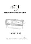
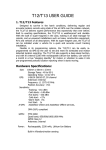
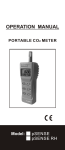
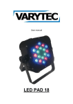
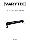
Pump Topper User’s Manual UNITS MUST SIT UPRIGHT FOR 24 HOURS BEFORE BEING POWERING UP! Power Requirements: (1) 15 amp circuit for air-conditioned/heated models 1 Pump Topper User’s Manual TABLE OF CONTENTS: Important Safety Information 3 Chapter 1: Installation Instructions 5 Chapter 2: Operation 6 02/08 tel: 303.412.0399 fax: 303.412.9346 www.displaydevices.com [email protected] 5880 Sheridan Blvd., Arvada, Colorado 80003 2 3 4 CHAPTER 1: INSTALLATION INSTRUCTIONS Mount the Riser 1. Determine mounting location on top of the gas pump and position the rectangular perforated riser on this location. Perforated Rectangular Riser 2. Once riser is positioned as desired, note the locations of the four sets of mounting holes in each of the four corners. Choose one hole from each corner, and mark it using a sharpie or pencil. Remove the riser. 3. Drill 3/8” diameter holes through the top of the pump at marked locations. 4. Replace the riser over the drilled holes. Using four 1” ¼-20 bolts, nuts, and eight ¼” washers, secure the riser to the top of the pump. Prepare the Electrical Power Access Hole 1. Using the diagram above, drill a 1” hole through the top of the pump in the location indicated. Be sure to drill this hole on the notched side of the separator. This will allow you to feed the power cable within the pump directly into the utility box in the Pump Topper. 02/08 tel: 303.412.0399 fax: 303.412.9346 www.displaydevices.com [email protected] 5880 Sheridan Blvd., Arvada, Colorado 80003 5 2. Have a certified electrician run the power cable from within the pump through the hole, leaving approximately 3” of metal conduit and 12” of exposed wire extending through the top of the pump. Installing the Pump Topper 1. Remove the lid of the utility box inside the Pump Topper. 2. You are now ready to position the Pump Topper on top of the riser. As you are lowering the Pump Topper, clamp the metal conduit in place and run the exposed wire through the hole in the bottom of the utility box. Place the Pump Topper on top of the riser ensuring there are no cables or other obstructions. 3. Line up the holes in the bottom of the Pump Topper with the nuts that are already integrated into the riser. Using four 1/4-20 by 5/8” long bolts, secure the Pump Topper to the riser. 4. Cut wire to suitable length and install into European terminal strip on the lid of the utility box. Reattach lid to utility box. POWER SUPPLY Main Air Conditioning Power Air Conditioning Compressor Heater Power Knockouts for Cat5 & (2) RS232 Ports RS232 Comm Port 110V/220V Power Entry Main Heater Power Circuit Breakers Display Power CHAPTER 2: OPERATION The Pump Topper is designed to be completely plug-and-play. Once power is connected, the media server and displays will power on and automatically begin playback of the pre-installed content. If the media server does not power on automatically, open one of the Pump Topper doors using the enclosed key, locate the media server, and press the red power button. 02/08 tel: 303.412.0399 fax: 303.412.9346 www.displaydevices.com [email protected] 5880 Sheridan Blvd., Arvada, Colorado 80003 6 Temperature Controller Operation The Temperature Controller in its basic configuration controls and displays the temperature of the enclosure. To start operation, turn on the power switch on the power supply. The controller will sound an alarm (if enabled), turn on fans for 10 to 20 seconds, and then reset the system to a start state. While operating, the display will show the current temperature and alarm status, if any. There are five parameters to set for your desired operation. Each is set in the same manner. On the control panel there are four buttons. The “Select Menu Item” button allows you to select the parameter you wish to adjust. The current setting is shown when you press the button. The next button (up arrow) will change the level up, and the next button (down arrow) will change the level down. The “Save” button will save your selections. The changes you‟ve made will be lost if you do not press “Save” after making your selections. The five parameters are as follows: Set Heat: Temperature at which the heater will turn on. Factory setting is 45 degrees (all settings in Fahrenheit). Set Air Conditioning: Temperature at which the air conditioner will come on. Factory setting is 72 degrees. Set Alarm Level: Temperature at which the alarm will sound. There is an onboard alarm, (which may be disabled) and a dry contact out to tie into an external alarm system. Factory setting is 110 degrees. Set Power Level: Temperature at which the switched AC outlet on the power supply will turn off. This is a last measure attempt to prevent damage to equipment by turning off power. Factory setting is 120 degrees. NOTE: If your current draw is over 10 amps do not use this switched AC outlet. Temperature Readout: Select either Fahrenheit or Celsius. Factory setting is Fahrenheit. 02/08 tel: 303.412.0399 fax: 303.412.9346 www.displaydevices.com [email protected] 5880 Sheridan Blvd., Arvada, Colorado 80003 7 Temperature Controller RS232 Interface (Version 70409) Active AC / Heater Hardware Standard three pin hookup, 2,3,5, on DB9. Baud rate 9600,N,8,1. No handshaking. Software ASCII letters followed by a delimiter, carriage return (ASCII 13). Commands from Host to Controller: Description Command Example Q1 Request Current Temperature Q1 Q2 Enclosure Status Q2 Q3 Door Switch Status Q3 Q4 Motion Sensor Status Q4 Q5 Request Ambient Temperature Q5 Q6 Request AC compressor Temperature Q6 Q7 Rx Request Temp Sensor 4 Temperature Request configuration of Unit – x is 1 to 11 1 – Operation mode 2 – Hysteresis 3 – User Display Temperature Units 4 – Number of fans with Tachometers 5 – Feedback mode 6 – AC ON/OFF Delay 7 – User Display Type 8 – Fan Level 1 / AC Level 9 – Fan Level 2 / Heater Level 10 – Alarm Level 11 – Power Cutoff Level Q7 R2 Axxx Fan Mode – Set level that zone 1 fans turn on AC Mode - Set level that AC turns on/off at (will turn on if temp above this level) A22 Bxxx Fan Mode – Set level that zone 2 fans turn on AC Mode – Set level that Heater turns on/off at (will turn on if temp below this level) B15 Cxxx Set Alarm Level (alarm on if hotter than this level) C30 Dxxx Sx Set Power Cutoff Level (cutoff if above this level) Set configuration of Unit – x is 1 to 7 1 – Operation mode 2 – Hysteresis 3 – User Display Temperature Units 4 – Number of fans with Tachometers 5 – Feedback mode 6 – AC ON/OFF Delay 7 – User Display Type D32 S25 xxx-temperature Carriage Return (13) 02/08 tel: 303.412.0399 fax: 303.412.9346 www.displaydevices.com [email protected] 5880 Sheridan Blvd., Arvada, Colorado 80003 8 Responses from Controller to Host: Command (see above) Response Q1 Txxx Q2 Description Example Current Temperature T23 O Temperature good, no problem O Q2 G AC On G Q2 H Heater On H Q2 I Alarm On I Q2 J Power has been switched off J Q2 F Temp Sensor Failure – Unit off F Q3 S (O,C) Door Switch is Open/Closed SO SC Q4 M Motion Sensor Tripped (0-No, 1-Yes) M0 M1 A,B,C,D K Received Set command, Executed OK K Q5 Axxx Current Ambient Temperature A24 Q6 Rx Cxxx Rx : xx… Current AC compressor Temperature Configuration information return Rx is the same as above, see notes for more info C57 R1:2 - X Can not understand Command X xxx-temperature Carriage Return (13) Notes: All temperatures are in Celsius. Set temperature ranges are from 1 to 80 Celsius. Return temperature has a space after the ‘T’ if positive, a – if negative. If temperature sensor failure, Return will be ERR – ‘T ERR’. Return temperature range is –60 to +80. In Fan Mode do not set Bxxx equal or below Axxx ! In AC – Peilter Mode do not set Bxxx equal or above Axxx! DO NOT ADJUST CONFIGURATION unless necessary Configuration information: S1, R1 – Operation Mode 1:fans, 2:AC, 3:Peilter S2, R2 – Hysteresis 2 to 9 minutes S3, R3 – User Temperature Units ‘C’ Celsius, ‘F’ Fahrenheit S4, R4 – Number of Tachometer Fans 0 to 14 S5, R5 – Feedback Mode ‘A’ Automatic, ‘M’ Manual (Manual means responses sent only when queried from host) (If in Auto, responses sent automatically: G,H,I,J,F,SO,SC,M0,M1) S6, R6 – AC on/off Delay 2 to 9 minutes S7, R7 – Display Type 0:none, 1: 2 Line LCD, 3: Graphical LCD R8 – Temp setting of level 1 (or AC on) R9 – Temp setting of level 2 (or Heater on) R10 – Temp setting of Alarm on R11 – Temp setting of power cutoff 02/08 tel: 303.412.0399 fax: 303.412.9346 www.displaydevices.com [email protected] 5880 Sheridan Blvd., Arvada, Colorado 80003 9 Ambient Noise Adjusting Audio Amplifier Operation This amplifier board will sample ambient noise level and automatically adjust output volume level to compensate for that noise level. It will only sample noise during quiet moments of program audio to prevent reading of its own output as noise. The board can be controlled from the front panel, or from a PC via RS232 communications. There are four buttons, four LEDs, and one bar graph on the user control panel. Right Button & LED: Mute toggle – pressing button will change state of mute from on/off, red LED on indicates output is muted. At power on, mute will be off. Bar graph: Depending on operation mode, will show level of program audio or ambient noise level. Two Buttons in middle: Adjust selected level up (left), or down (right). Left Button: Change modes of operation Mode 1 – Normal, Green LED on When first switching to this mode, display will show set output level, then switch to showing input audio level. Up/Down buttons will adjust output volume level, while adjusting display will show output level. If noise compensation is off, RED led will blink at slow steady rate. During normal operation RED led blinks when sample is taken of ambient noise level. If program audio is too high, it will delay sample. During this delay the yellow LED will be lit. Mode 2 – Show Ambient noise level, Yellow LED on Displays ambient level on bar graph, adjust maximum volume output when noise compensation is on. If noise compensation is off, RED led will blink. Use Up/Down buttons to adjust maximum noise level, while adjusting level amplifier will temporary play at that level to allow user to hear level that you have adjusted to. Mode 3 – Turn Noise comp on/off In this mode, UP button will turn noise compensation on, DOWN button will turn noise compensation off. Bar graph moving rapidly shows noise comp is on. Noise comp is always on when power is first applied. Adjustment Procedure: Turn on the system and have audio playing normally. The audio source (such as a computer) should be adjusted to provide maximum volume output with no distortion. Place the amplifier into Mode 1 and adjust the volume to the level desired when no noise is present in area. Place the amplifier into Mode 2 and adjust the volume to the level desired when maximum noise is present. Switch mode back to Mode 1. 02/08 tel: 303.412.0399 fax: 303.412.9346 www.displaydevices.com [email protected] 5880 Sheridan Blvd., Arvada, Colorado 80003 10 RS232 Protocol Hardware: 9600 baud, no parity, one stop and start bits. Three wire hook up (transmit, receive, ground). Software: Commands to the board are multi-byte, with terminator (ASCII 13), one byte response with no terminator. Commands to Amp „M‟ (77) – Mute On „O‟ (79) – Mute Off „U‟ (85) – Volume Up „D‟ (68) – Volume Down „Vxxx‟ (86) – Volume Level „N‟ (78) – Automatic Noise Level Adjustment ON „S‟ (83) – Automatic Noise Level Adjustment OFF Responses from Amp „R‟ (82) - Received Command / Ready „U‟ (85) - Invalid Command NOTES: xxx – Volume Level from 1 to 100, 100 highest. Exp: V50 02/08 tel: 303.412.0399 fax: 303.412.9346 www.displaydevices.com [email protected] 5880 Sheridan Blvd., Arvada, Colorado 80003 11