1
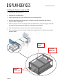
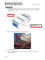
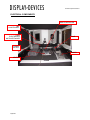
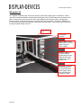
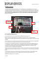
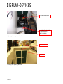
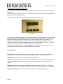
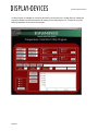
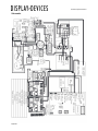
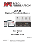
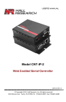
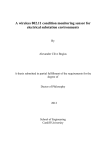
PJE-1000
Outdoor Projector Enclosure
Installation Manual
Thank you for purchasing this Display Devices product. Our products are designed to be maintenancefree, saving you future service time. If you experience any difficulties, please contact tech support at 303412-0399 x 24. Thank you for your support.
tel: 303.412.0399
fax: 303.412.9346
www.displaydevices.com
[email protected]
5880 Sheridan Blvd., Arvada, Colorado 80003
Custom Projector Enclosure
Note:
It is the responsibility of the dealer installer to ensure this product is properly supported and
meets all local building codes. Ensure the ceiling structure is capable of holding at least four
times the combined weight of the enclosure (400 lbs.) and projector (100 lbs). This is a minimum
requirement. Follow any local or state codes that apply to your specific area.
Installation Tools Required:
Philips Head Screwdriver #1 and #2
Wire-management tools (side cutter, stripper, crimper, etc.)
S.A.E. Wrench Set – based upon your mounting hardware
5/16” T-handle Allen wrench
Bubble level
Frosty cold beverage
4/18/2011
Custom Projector Enclosure
Installing the Projector inside the PJE
1. Open the PJE side access door.
2. Open the PJE front access door.
3. Unlatch right and left spring pins located at the front of the drawer slides.
4. Use two hands and pull the AVStack cage. Be careful when fully extended out that the entire
enclosure does not tip forward.
5. Place the projector onto the mounting pan within the AVStack frame, align mounting pan holes with
the projector mounting points and attach with enclosed mounting hardware.
6. Push the AVStack frame back into the enclosure and lock the spring pins.
7. Turn the thumbwheels on the AVStack to adjust pitch, height and roll. See AVStack Cage diagram
below for details
AVSTACK
FRAME
PITCH AND
HEIGHT
ADJUSTMENT
ROLL AND
HEIGHT
ADJUSTMENT
4/18/2011
Custom Projector Enclosure
Mounting the PJE
1. Use the two Unistrut channels on the top of the enclosure to attach to your structural ceiling/truss.
We recommend ½” strut hardware. You may attach rated C-Clamps or Cheesboroughs to these
structural channels.
UNISTRUT
ELECTRICAL
KNOCKOUTS (EKO)
2. Raise the unit with an equipment lift (or lower truss to enclosure).
3. Tighten all hardware.
4. Bring cabling through the holes on the side of the enclosure – secure both power and signal
cables with strain relief.
4/18/2011
Custom Projector Enclosure
ELECTRICAL COMPONENTS
MAIN CONTROLLER
AIR
CONDITIONER
USER
ELECTRONICS
SWITCHED POWER
FUSE
POWER
CUTOFF
POWER
HEATER
4/18/2011
Custom Projector Enclosure
Wiring the PJE
Two separate isolated 20-amp circuits are required to power the projector and air conditioner. Stub-in
rigid or flex conduit and feed the electrical circuits through the two ½” EKO holes on the enclosure’s side
panel. Connect one circuit into the PJE J-Box, and another into the Projector J-Box. See the photo
below for details. Note that the locations to connect power are also labeled. The third ½” EKO hole on
the enclosure’s rear panel is for projector video/control input and output. Stub-in rigid or flex conduit and
feed signal cables through this hole.
Side Access
Door
Temperature
Controller
Signal J-Box: Empty
junction box for incoming
projector signal or
control cabling.
Projector J-Box: AC
outlet for customer
supplied projector and
additional electronics
(media server, audio
amplifier, etc.)
PJE J-Box: AC outlet
for PJE components –
DDI Control Box and
Power Supply, which
drive the onboard air
conditioner, heater
4/18/2011
Custom Projector Enclosure
DDI Main Controller
The main controller sends control signals via a communication bus to the heater and A/C in order to
maintain the temperature within the enclosure. The temperature can be programmed by the user via the
temperature controller. The main controller accepts outside communication through ethernet, RS-232, or
USB. Switched power disables power to the projectors and additional components when programmed
internal enclosure cutoff temperature level is met. The main controller is used in both fan cooled and
heater-A/C enclosures.
ETHERNET
(OPTIONAL)
USB
COM
RS-232
CONTROL
Air Conditioner Maintenance
Air Conditioned units must sit upright for 24 hours before powering up the unit.
DDI air conditioners are designed to be long lasting and maintenance free. Other than regular
maintenance as specified in the user manual, only a qualified technician should perform work to the unit if
required.
Upon powering up the unit the compressor will not activate for 5 minutes. Any time power is interrupted
to the enclosure the air conditioning compressor has a 5 minute warm up time.
If the enclosure is mounted at more than a 10° angle (forward tilt) you will need to readjust the angle of
the compressor. A sticker on the front of the compressor access panel shows the angle of adjustment.
Loosen the nut and then adjust the angle reading to the angle the enclosure is mounted at. This
information may not be applicable to all applications.
Inspect and clean the air filter after two weeks of operation. The frequency of cleaning will be dependent
upon the environment the enclosure is located in (i.e., dust, leaves, etc.). Filter media can be rinsed with
water.
In some cases it is necessary to provide a place other than the A/C housing for condensation to drain.
Use knockouts or provide your own in the location which works best for your installation site.
Caution! Keep fingers out of moving fans.
4/18/2011
Custom Projector Enclosure
COMPRESSOR
LOOSEN TO ADJUST
COMPRESSOR
(BOTH SIDES)
Adjusting the compressor for tilt.
WING NUTS
FILTERS
Cleaning and replacing the filter
4/18/2011
Custom Projector Enclosure
Temperature Controller Operation
The Temperature Controller in its basic configuration controls and displays the temperature inside the
enclosure.
The control module is power by 24 Volts. The status led will blink on and off continuously when the unit
has power and is functioning correctly.
While operating, the display will show the current temperature and status, if any.
User Display
The “Select Menu Item” button allows you to select the parameter you wish to adjust. The current setting
is shown when you press the button. The next button (up arrow) will change the level up, and the next
button (down arrow) will change the level down. The “Save” button will save your selections. The
changes you’ve made will be lost if you do not press “Save” after making your selections. To start
operation, turn on the AC switch on the power supply. The controller may sound an alarm, and the fans
will turn on for 10 to 20 seconds. The system will then reset to a start state.
There are five parameters to set for your desired operation. Each is set in the same manner. On the
control panel there are four buttons. The five parameters are as follows:
Fan Only Version
Set A/C Level: Temperature at which the first set of fans will come on. Factory setting is 84 degrees.
The fans will run at slow speed. The fan speed will increase as temperature level increases.
Set Heat Level: This setting is not used in the fan only application.
Alarm Level: Temperature at which the alarm signal will activate. There is an onboard alarm, (which
may be disabled) and a dry contact out to tie into an external alarm system. Factory setting is 111
degrees.
Cutoff Level: Temperature at which the switched AC outlet for the display will turn off. This is a last
measure attempt to prevent damage to equipment by turning off power. Factory setting is 120 degrees.
Temperature Readout: Select either Fahrenheit or Celsius. Factory setting is Fahrenheit.
4/18/2011
Custom Projector Enclosure
Air Conditioning / Heat Version
Set A/C Level: Temperature at which the air conditioner will come on. Factory setting is 77 degrees.
There are three temperature sensors with an air conditioned environmental enclosure with a single A/C.
The main sensor is located near the display. The other two sensors are located in the air condition unit
one reads the ambient air and the other reads the compressor temperature. There is an additional
compressor sensor for each additional A/C unit.
The main sensor controls the air conditioner, turn on temperature, heater turn on temperature, alarm
activation turn on temperature, and the power cutoff temperature. The default settings are AC ( 77/25),
Heater ( 55/13), Alarm ( 98/37), and Power Cutoff (102/39) degrees Fahrenheit/Celsius.
Example using the default temperatures as reference:
If the main sensor reads a temperature of 77 degrees or above the air conditioner will turn on.
If the main sensor reads a temperature of 55 degrees or below the heater will turn on.
If the main sensor reads a temperature of 98 degrees or above the alarm will sound (refer to protocol).
If the main sensor reads a temperature of 102 degrees or above the power to the display will cutout
protecting the display.
The main sensor and the compressor sensors have to be working or the air conditioner unit will not turn
on. The evaporative fans (cold side of A/C) will turn on at 77 degrees and when the air conditioner is
running and will continue to run for a little over one minute after the air conditioner
turns off. The compressor fans (hot side of A/C) will turn on when the air conditioner unit is running.
Set Heat Level: Temperature at which the heater will turn on. Factory setting is 55 degrees (all factory
settings in Fahrenheit).
Set Alarm Level: Temperature at which the alarm will sound. There is an onboard alarm, (which may be
disabled) and a dry contact out to tie into an external alarm system. Factory setting is 98 degrees.
Set Cutoff Level: Temperature at which the switched AC outlet on the display cutoff module will turn off.
This is a last measure attempt to prevent damage to equipment by turning off power. Factory setting is
102 degrees. NOTE: If your current draw is over 10 amps do not use this switched AC outlet.
Temperature Readout: Select either Fahrenheit or Celsius. Factory setting is Fahrenheit.
Options: The motion sensor detects vibration and will send a command on the RS232 line see the
communication protocol. The Door sensor will send a command on the RS232 when a change of state of
the switch occurs. See the communication protocol.
4/18/2011
Custom Projector Enclosure
A Utility Program is available for monitoring and setting up the enclosure. Display Devices’ makes this
program available to qualified technicians for setting up and analyzing the unit. Please call your DDI
sales representative for access to this program.
4/18/2011
Custom Projector Enclosure
Environmental Communications Protocol
System
Display Devices environmental controller is designed to accommodate a wide variety of configurations to
maintain a working environment for electronic devices, specifically various output displays. It is intended
to be used in a sealed enclosure manufactured by Display Devices.
Format
Simple ASCII, comma delimited fields, carriage return terminated. Depending on option ordered,
communications connection is either serial RS232, USB, or Ethernet. If RS232, then communications
parameters are 9600,N,8,1. If Ethernet, protocol is TCP. There is extensive documentation on the
Ethernet communications at Lantronix web site, device is Matchport AR. Port used is serial tunnel #1.
Usage Notes
Only use messages that relate to your configuration. Requesting door state, or status of AC unit #3 does
not work if you do not have a door switch, or AC unit #3.
When state of three feedback messages change, automatic messages will be sent back to host. They
are 8 (door), 9 (motion sensor), and 5 (General Status). Example; if door is opened, then door state
message (8) is sent to host. The request , 108, is available to verify in case it is needed.
Do not send commands to controller at a rate faster than one per second.
Host to Controller Messages
General Status Request – Code 105
Function Code
Example 105 <CR>
Request general status information – Send up to one per five seconds or slower.
AC Unit Status Request – Code 106
Function Code, AC Unit #
Example 106,2 <CR>
Request status of AC Unit 2. Unit # are 1 to 5, do not enter # above what you have.
System Error Request – Code 107
Function Code
Example 107 <CR>
Error state of various components in enclosure.
Door Request – Code 108
Function Code
Example 108 <CR>
Request door state, open or close.
Motion Sensor Request – Code 109
Function Code
Example 109 <CR>
Request state of sensor, movement detected or not. This is momentary, does not hold state.
4/18/2011
Custom Projector Enclosure
Auxiliary module On/Off – Code 110
Function Code, Module #,On/Off
Example 110,12,1 <CR>
Turns aux module #2 on. Used for various devices – pumps, lights, relays, etc.
Aux module 1 to 5 is Module # 11 to 15, respectively
1= On 5=Off
Water Present Request – Code 111
Function Code
Example 111 <CR>
Request state of water present sensor.
Request HB Status – Code 112
Function Code
Example 112 <CR>
Interface to HB LED backlight. Request current status.
Request Controller Firmware Version – Code 113
Function Code
Example 113 <CR>
Request controller firmware version number.
Controller Configuration – Code 130
Function Code, Setting Number, Configuration
Setting Number
Configuration values
1-Turn on AC temperature
21 to 43 C
2-Turn on Heat temperature
12 to 1 C
3-Hysteresis (AC only)
1 to 5
C
4-AC Turn On Delay
0 to 6 Minutes
5-Alarm temperature
32 to 43 C
6-Cutoff temperature
37 to 48 C
7-Dehumifier percent On
20 to 90 %
(0 is no dehumifier)
8-Defroster Level On
10 to 90
(0 is no defroster)
9-HB LED max temp
32 to 43 C
(0 is no HB interface)
10-Number of AC units
0 to 5
11-Type local user display
0 to 5
12-Water Sensor
0 to 1
13-Display Units (local display) 0 to 1
(0 = Celsius, 1 = Fahrenheit)
Example 130,1,24<CR>
(Turns on AC at 24 C)
Example 130,2,10<CR>
(Turns on Heat at 10 C)
Example 130,3,2<CR>
(sets AC hysteresis to 2 C)
Example 130,4,1<CR>
(sets delay time for AC turn on to 1 minute)
Example 130,5,35<CR>
(Turns on alarm at 35 C)
Example 130,10,2<CR>
(sets number of AC units to 2 )
There are other settings above 13, must be used only by factory personnel.
Request Configuration Setting – Code 131
Function Code,Setting Number
Example 131,2 <CR>
Request setting for heat turn on.
4/18/2011
Custom Projector Enclosure
Controller to Host Messages
Return General Status – Code 5
Function Code, Inside Temperature, Inside Humidity,Outside Temperature,Voltage,Current
Mode,Evaporator fan speed.
Example 5,21,30,37,24.1,2,90 <CR>
General Status – Example above:
Inside temperature – 5 C
Inside Humidity – 21%
Outside Temperature – 30 C
Control Voltage – 24.1 Vdc
Current Mode – 2= AC is on
Evaporator Fan speed = 90%
Modes: 1- Normal Temp Range
2- AC on
3- Heat on
4- AC on, alarm level tripped
5- AC on, cutoff level tripped
This code is returned automatically when mode changes from one level to the next.
Mode can be 1, and evaporator fan speed is 60%. This indicates that temperature range is
normal and the internal circulation fans is on. Temperature readings are not valid if that sensor is
in error state.
Return AC unit Status – Code 6
Function Code, AC unit #, Compressor Temperature, Fans, Temperature 2
Example 6,1,44,1,0 <CR>
AC unit #1 compressor is 44 C and fans are good. 1=good fans, 0=fan error
Not all units have error detection on fans.
Errors returned on code 7 (below) have precedence over errors returned here.
Fan error on this return code not implemented, use code 7 below.
Return System Errors – Code 7
Function Code, temperature errors, sensor errors, fan errors, module errors, module errors
Example 7,0,0,1,128,0 <CR>
Fans bad AC #1, heater module no response
Each return value is decimal for one byte binary: 5 = 00000101 Each bit is a status of good(0) or
bad(1)
Bit
Temperatur
e
Errors
Fan Errors
Sensor Err
Modules
1-8 Errors
Modules
9-15 Errors
4/18/2011
7
Inside
Enclosur
e
6
HB
LEDs
Inside
Enclosur
e
Heater
Outside
Water
Sensor
Cutoff
#2
Aux
#5 (15)
Cutoff
#1
Aux
#4 (14)
Water
Present
5
4
AC#5
Comp
3
AC#4
Comp
2
AC#3
Comp
1
AC#2
Comp
0
AC#1
Comp
AC #5
AC #5
AC #4
AC #4
AC #3
AC #3
AC #2
AC #2
AC #1
AC #1
AC #5
AC #4
AC #3
AC #2
AC #1
Aux
#3(13)
Aux
#2(12)
Aux
#1(11)
Defroster
Dehumdifie
r
Custom Projector Enclosure
Bits are set when: Temperature errors- exceed alarm point or above compressor limits.
Fan errors- fans with feedback register non-functional.
Sensor Errors- Sensors do not respond
Modules Errors- Modules do not respond
Water Present – 1 if water sensor detects water
Fan errors may appear immediately after AC unit is started. Certain model fans take a while to
start, and during that time an error may appear. It is best to either wait one minute after AC
starts, or check minutes apart and see if error persists. Fans must be on to detect errors.
Ambient sensor error is frequent but should be ignored unless consistent over 5 reads.
Return Door State – Code 8
Function Code,door
Example 8,1 <CR>
Door is open. 1=Door open, 0=Door Closed
Return Motion State – Code 9
Function Code, Motion Sensor
Example 9,1 <CR>
Motion sensor activated. 1=currently activated, 0=not activated
ACK for Auxiliary On/Off – Code 10
Function Code, Module #, On/Off
Example 10,11,5 <CR>
Acknowledgement of command to turn aux #1 off. 1=On, 5=Off
Ack only for command, not if it executed it. Check errors (code 7) for results.
Return Water Present – Code 11
Function Code, water present
Example 11,0 <CR>
No water sensed. 1=water present, 0=no water
Return HB LED status – Code 12
Function Code, temperature, percent power
Example 12,32,75 <CR>
HB LEDs are 32 C running at 75% power.
Return Firmware Version Number – Code 13
Function Code, Version #
Example 13,V100429 <CR>
Firmware Version Number of CPU, always V followed by 6 numbers
ACK configuration setting – Code 30
Function Code, Setting Number, ACK
Example 30,3,1 <CR>
Setting #3 (hysteresis) was successful. 1=Good, 0=Bad
Return Configuration – Code 31
Function Code, Setting Number, configuration
Example 31,2,11 <CR>
Setting #2 (heat on) is 11 C.
4/18/2011
Custom Projector Enclosure
Schematic
4/18/2011