1
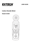
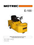
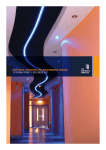
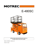
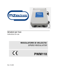
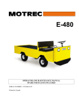
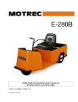
Zero Emission
Vehicles Australia
Introduction
Congratulations on your purchase of a ZEVA MC600C motor controller.
http://www.zeva.com.au
The MC600C was designed to be one of the best value, most reliable and easiest to use motor
controllers available for electric vehicles. It utilises the latest in power semiconductors to make
it one of the most efficient motor controllers available – over 99% at all times. Featuring dual
microprocessors for redundant safety, an advanced throttle algorithm for the smoothest driving
experience, silent operation at all times, a compact weather-resistant air-cooled housing, and
industry-standard CAN bus connectivity for monitoring operation, programming settings, and even
optional throttle control over CAN bus.
We hope it provides you years of reliable service.
Safety Warning
Electric vehicle motor controllers are high powered devices which involve potentially lethal
voltages and currents. Proper precautions and electrical safety procedures should always be
observed, voltages above 110VDC should be considered dangerous, and vehicles should never
be worked on while contactor(s) are engaged. Please read this manual carefully before using
the controller to ensure correct installation and operation. If you are unsure of anything, please
contact us before proceeding.
MC600C
150VDC 600A motor controller
for Series DC and PM DC motors
We have endeavoured to make a safe and reliable product which performs as described, however
since ZEVA has no control over the integration of its products into a vehicle, we can assume no
responsibility for the safety or functionality of the completed vehicle. It is up to the end user to
determine the suitability of the products for the purpose employed, and the end user assumes all
risks associated. Products should only be installed by suitably qualified and experienced persons,
and should always be used in a safe and lawful manner.
Tech support and warranty information
Table of contents
page
1) Introduction
1
2) Safety Warning
1
3) Tech Support and Warranty Information
1
4) Features and Specifications
2
5) Installation
3
6) Power Wiring
4
7) Control Wiring
6
8) Operation
8
9) CAN Bus Communications
10
The MC600C motor controller is covered by a 12 month warranty against manufacturing faults or
failures under normal operating conditions. The warranty does not cover misuse of the product,
including but not limited to: Excessive voltage or reversed polarity on input terminals, short
circuits on output terminals, excessive voltages applied to control wiring, opening of housing and/
or modification of internals, severe impact damage (e.g due to vehicle crashes), submersion in
water.
We have taken great care to design a safe and reliable product, but faults can happen. If you
believe your motor controller has a fault, please contact us via our website to discuss. If it is
determined that a hardware fault is the likely cause, we will provide an RMA number and return
address to proceed with repairs.
If you have any questions not covered by this manual, please contact us via our website:
http://www.zeva.com.au/Contact
1
Features and Specifications
Features:
• Smooth, hybrid throttle algorithm for familiar driving feel
• Thermal cutback and over-temp protection
• Configurable operating parameters via CAN bus interface
• Multicolour status LED for visual status feedback
• Durable weather-resistant extruded aluminium housing (approx IP44)
Installation
The motor controller may be installed in any orientation. Usually, installation close to the motor
is best in order to keep power wiring to the motor short. The enclosure is weather resistant but not
fully waterproof, so it is best installed in a location with some protection from the elements. If it
may be in the direct path of water, splash guards are recommended.
The controller’s continuous power capabilities depend somewhat on the amount of airflow around
the case for convection cooling. If the install location has very little airflow, the controller may
benefit from added convection cooling via fans or ducting. (Or for highest sustained power, the
controller may be base-mounted to a fan-forced convection or water cooling block.)
• Compatible with optional fan-forced air or water cooling blocks for higher sustained power
• Adjustable motor idling function for automatic gearboxes or maintaining auxiliaries
160
• Support for most throttle types including 3-wire 0-5V, 2-wire 0-5KΩ, and HEPA pedals.
• Fully isolated logic and power electronics
160
• Robust I/O protects controller against external wiring faults
• High pedal lockout (protects against non-zero throttle on startup)
142
70
• Independent hardware overcurrent protection system (“desat” detection)
130
• Self diagnostics with error detection including overcurrent, low voltage on power and logic
supplies, internal programming corruption, and internal sensor faults.
Specifications:
• Battery voltage range: 12-144V nominal (9-175V absolute maximum)
• Up to 45x LiFePO4 cells, 40x LiCo cells or 12x 12V lead acid
• Current rating: 600A peak (1 minute), 200A continuous
• Power: 90kW peak, 30kW continuous
206
• Power device type: MOSFET
• On-state voltage drop: 0.6V at full power, 0.2V at continuous rating
• Switching frequency: 16KHz
• Operating temperature: -20˚C to 90˚C (thermal cutback from 70˚C)
• Logic power supply: 12V nominal (8-18V range), 200mA max, internally fused
• Dimensions: 210x130x95mm housing only, 265x156x106mm inc terminals and brackets
• Weight: 3.5kg
Package contents:
• 1x MC600C motor controller
• 1x 4-pin plug, 1x 5-pin plug
• 4x M8x25 bolts, washers, and nuts
• 1x User manual
2
Controller dimensions and mount locations
The motor controller comes with brackets for mounting with four 6mm or 1/4” bolts on a 142 x
160mm spacing. Spring washers under the heads of mounting bolts are recommended to prevent
the bolts from loosening over time due to vibration.
Alternatively the mounting brackets may be removed, and the four holes underneath the housing
used to fasten to a panel from beneath. The holes are M6 thread on a 70 x 160mm spacing.
Caution: Since these threaded holes penetrate the housing, ensure that bolts do
not extend more than 20mm into the case or they may damage components inside!
3
Power Wiring
Remember..
The traction circuits in electric vehicles involve very high power levels, with potentially lethal
voltages and currents involved. Always observe proper precautions and safety procedures when
working on electric vehicles. Always wear safety glasses, use insulated tools where possible, and
check for dangerous voltages with a multimeter before undertaking any maintenance!
If you are unsure, always consult with an experienced EV technician before proceeding.
Typical wiring diagram
The diagram below shows the basic power wiring. Orange lines represent power cables, which
should be 50sqmm or 1/0 AWG in size, or larger. Control wiring to/from controller not shown.
Tips for best performance
• Power cables around 50sqmm or 1/0 AWG in size are recommended for all power wiring
between batteries and motor controller, and 50-95sqmm (1/0 to 4/0 AWG) cable between the
motor controller and motor, where average currents are higher. It is best to use double insulated
cable with an orange sheath for compliance with electrical standards.
• Ensure all power terminals and connections in your traction circuit are clean and tight. Always
use either spring washers or Nyloc nuts to ensure connections will not loosen from vibration
over time. Poor connections have a higher resistance, which can cause them to become hot
when conducting large currents – potentially damaging components.
• It is essential to have a precharge device to charge up the motor controller’s internal capacitor
bank before closing the main contactor. Closing the main contactor without first precharging
the controller causes a huge current spike which can damage contactors, often welding their
contacts together. A 1KΩ 10W precharge resistor permanently across the main contactor can
work, but is not the safest solution as it does not truly isolate the controller when the key is off.
A better solution is a 2-stage automatic precharger such as our ZEVA Smart Precharger, or an
EVMS with built-in precharger.
• Ensure you have an appropriately rated main contactor and fuse protecting your traction circuit.
Examples of suitable contactors are the Kilovac EV200 or LEV200, Gigavac GX14, Albright
SW200, or Nanfeng ZJW400A.
• For a fuse, a 300A semiconductor type with sufficient DC voltage rating is recommended, such
as those from Bussmann, Ferraz-Shawmut, Mersen, Littelfuse, etc. Large fuses tend to be very
slow to blow, typically able to carry twice their rated current for about 1 minute. As such it is
best to use a fuse with a rating slightly above the continuous rating of the motor controller, rather
than one rated for the maximum motor controller current.
• The MC600C motor controller uses aluminium busbars. Aluminium itself is a good conductor
of electricity, but unfortunately the (invisible) aluminium oxide which forms on its surface is
a poor conductor. The power terminals are supplied cleaned and with a thin layer of Noalox
contact paste applied to prevent re-oxidation. This paste should be left on the terminals when
are attaching power cables. The force of tightening the bolts will displace the grease and seal the
contact area to prevent corrosion over time.
Basic power wiring diagram for MC600C controller
Caution: Always double check power wiring before turning the system on for the
first time, because reversed polarities or short circuits can do a lot of damage!
• The power cables in electric vehicles carry a large amount of power, and can emit a lot of
electromagnetic interference (EMI) depending on their physical layout. To minimise EMI, it is
best to keep the positive and negative cables close together – both the power cables from battery
pack to controller, and controller to motor. To further reduce EMI, the cables may be twisted
around each other. (For further details on why twisting cables together is helpful for EMI, refer to
http://www.wikipedia.com/wiki/Twisted_Pair)
When first powering up the completed system, wiring mistakes or faulty throttle
devices could cause unexpected power to the motor, which risks injury or vehicle
runaway. It is highly recommended that the drive wheels be off the ground, and
that nobody is standing in front of or behind the vehicle at the time.
4
5
control wiring
Plug identification
The MC600C uses two aviation-style screw-lock plugs for all control/low power connections – one
with 4 pins for the throttle and one with 5 pins for power input and CAN bus connections. The
diagram below shows pin identifications as viewed on the controller case.
5V Out
Thr A
Thr B
Gnd
Shield
CAN L
CAN H
Gnd
12V in
Pin identification for control wiring plugs
Plug 1: Throttle
Plug 2: Power and CAN
• 5V: Output power supply for throttle. Max
50mA output (internal self-resetting fuse)
• 12V In: Connect to a key-switched 12V
supply so the controller comes on when
the key is turned on. Often wired in parallel
with your main contactor. Maximum voltage
range 8-18V input, approx 200mA draw.
• Gnd: Ground connection for throttle
• Throttle A: First throttle input, usually the
analog level, 0-5V input
• Throttle B: Second throttle input, either
enable switch or 2nd analog, 0-5V input
• Gnd: Connect to ground / vehicle chassis
• CAN L and CAN H: Two wires for CAN bus
communications
• Shield: Not required (usually for passthrough of shielding on CAN-bus cables)
Wiring up the plugs
The plugs are opened using a small jewellers screwdriver to remove the screw on the side of the
rear shell, which then comes away with a small counterclockwise twist.
Feed wires through the back of the rear shell before attaching to the pins to ensure the case can
go together again after wires are attached. For reliable connections, be sure to “tin” (add solder to)
both the wires and the contacts before soldering them together.
The shell also has a cable stress relief clamp at the rear which should be fastened down to hold the
cables. If your cables are too small for the clamp to engage, you can wrap some insulation tape
around them to increase the diameter and ensure the clamp is able to hold them in place.
6
Example wiring of aviation plugs: Disassembled (left), wiring (middle), complete (right)
• Since the logic wiring is necessarily quite close to the traction circuit power cables, to avoid
Electromagnetic Interference (EMI) it is best to use shielded cables, or twist wires (such as 12V
and Ground) together. Also avoid running logic wiring in parallel with power cables for long
distances, as it increases noise due to crosstalk.
• The logic board only requires 200mA current, so as small as AWG28 wire may be used for the
power supply. However, if not enclosed in a shielded sheath, it is best to use larger cable around
18AWG+ for better mechanical strength/durability.
• All control wiring is galvanically isolated from the power terminals. In most cases the control
wiring will share a common ground (the vehicle chassis) with your vehicle’s existing 12V system,
and the traction circuit should remain electrically isolated for safety.
Throttle device
The MC600C controller supports a variety of different throttle types, which may be selected via
CAN bus interface. (Controller expects Type 1 throttle by default.)
• Type 1, 0-5V + Enable: Any throttle device which outputs a 0-5V level representing 0-100%
throttle may be used. Non-contact Hall Effect types are the best option due to their reliability and
virtually unlimited lifespan. They should have three wires to connect to Gnd, 5V and Throttle
A (0-5V level). The Throttle B pin should be connected to 5V through the enable switch on the
potbox (COM and NC terminals) for redundant safety in case of hall sensor fault.
• Type 2, 0-5KΩ + Enable: Although not considered a great option due to their tendency to wear
out and become unreliable over time, legacy 2-wire resistive 0-5KΩ potboxes (such as the Curtis
PB-6) can be used. The two throttle wires connect to Throttle A and 5V (either polarity). The
enable switch should be wired between 5V and Throttle B, using the COM and NC terminals.
• Type 3, Hall Effect Pedal Assembly (HEPA): HEPA pedals are becoming the industry standard
for throttle devices in vehicles as they offer high reliability and safety through the use of dual
(redundant) hall effect sensors. A variety of different HEPA pedals are available, typically having
6 wires for two independent 3-wire hall effect type throttles. The MC600C was designed to work
with pedals providing dual analog outputs of around 0.7V–3.5V and 1.4V–4.2V. Use the Gnd
and 5V pins on Plug 2 to provide power to both sensors. The 0.7-3.5V signal connects to Throttle
A and the 1.4V-4.2V signal to Throttle B. With a HEPA throttle, the controller can detect a throttle
fault if any four of the wires are disconnected, or if either of the throttle sensors are faulty.
7
Operation
The idle speed and torque are configured via CAN bus. Voltage effectively controls target motor
speed and current controls the torque it will use to get there. Ideal values will depend on your
motor and vehicle, but a good starting point is 6V idle voltage and 100A idle current.
Many drivers are accustomed to keeping revs low in their petrol vehicles in order to maximise
efficiency, since petrol engines are very inefficient at high revs. Well, electric drive systems are the
other way around! The single most effective way to maximise performance from your motor and
controller is to keep your motor revs high – around 3000-4000rpm with most Series DC motors.
Caution: Electric motors can suffer damage if they remain stalled with current
flowing for extended periods of time. Idle functionality is NOT recommended for
“direct drive” vehicles, and in the case of vehicles with manual transmissions, be
sure to put the clutch in when coming to a stop.
tips for best performance
For a given power output, driving a motor at higher speed uses more voltage but less current,
which reduces copper losses in the motor and resistive heating in the controller. Dropping down
a gear reduces motor amps by about 30%, which can actually halve the heat generated in your
controller – and hence double the continuous power capability. (Caution: Most Series DC motors
are rated to 5000rpm max so be careful not to exceed this speed.)
thermal protection
If your controller heatsink temperature reaches about 70˚C (150˚F), the controller will commence
thermal cutback, smoothly reducing power to mitigate further heating. The status LED will flash
green/red while in this state. If the controller temperature reaches about 90˚C (200˚F), the controller
will shut down completely to avoid overheating which could damage components.
The controller’s power rating depends somewhat on airflow to cool the housing. If you are
experiencing thermal cutbacks, it may be useful to add fans or ducts to increase airflow. Driving
more slowly and keeping motor revs high will also help keep the motor controller cooler. If
thermal problems persist, it may be useful to add an external water cooling system or external
heatsink, which can be mated to the flat aluminium base of the controller (with thermal paste in
between).
12V logic supply
The MC600C has an internal regulated power supply on its 12V input which allows it to operate
safely and correctly over an input voltage range of 8-18VDC. As a safety precaution, the controller
will shut down if it detects the control voltage input dip below 8V.
In most installations this will never happen, but if your 12V battery and/or DC/DC converter is very
weak, the voltage may dip when loads such as headlights are turned on, which can trip out the
motor controller. This should be rectified by by fitting a stronger battery and/or DC/DC converter.
Motor Idling Functionality
The MC600C includes a basic motor idle functionality, based on a low target speed with low torque
limit. It does not use an RPM sensor for speed feedback, so the speed may vary depending on load.
However it is a simple and effective solution for EV conversions with automatic transmissions
which require the motor to keep turning to maintain oil circulation in the gearbox, or for vehicles
using OEM power steering pumps, air-conditioning compressors, alternators, etc.
8
internal capacitor warning
Motor controllers have a large bank of capacitors on their input, which can remain charged for a
long time after the controller is powered off. Exercise caution if undertaking vehicle maintenance
soon after driving, as there may be significant voltage across the controller’s input power terminals,
even if your main contactor is open. Always measure the voltage across the controller with a
multimeter before performing any maintenance.
LED status and error codes
The MC600C has a multicolour LED on its front panel for providing visual feedback on the
controller’s operating status. The following table summarises the codes you may encounter
(multiple dots representing a flash sequence):
LED Code
Condition
Comment
Controller on
(No errors)
Thermal cutback
Controller temperature above 60˚C. Power reduces
slowly towards thermal shutdown threshold.
Thermal shutdown
Controller temperature above 90˚C. Thermal
shutdown until temperature reduces.
Battery voltage low
Voltage at power terminals below minimum setting.
Power stage disabled until voltage increases.
Supply voltage low
Supply voltage below 8VDC. Latches on for safety.
Fix 12V supply then power cycle controller.
Throttle error
Invalid voltage or level mismatch on throttle. Error
latches on for safety until zero throttle is detected.
High pedal lockout
Non-zero throttle detected at startup. May indicate
foot on pedal, or a faulty throttle device.
Corrupt settings
Fault in the internal memory. Will automatically
revert to default settings on next startup.*
Desat error
Hardware overcurrent fault. May indicate damage to
internal power devices or short circuit in motor.*
9
Internal sensor fault
An internal sensor returned an invalid value.*
* These rare errors may indicate a hardware fault in the controller – please contact us!
Caution: There are no user-serviceable parts inside the controller.
Do not attempt to open the controller as this will void warranty!
can bus communications
Refer to the Operation: Motor Idling section for more information.
CAN protocol description
This section describes the CAN communication particulars for those wishing to create their own
interface with the motor controller over CAN bus. Default CAN bus speed is 125kbps and uses
format 2.0A. The motor controller is intended to always be on the end of a CAN bus, so has a
120Ω termination resistor built-in. (Please contact us if you require a controller with different bus
settings or data formats.)
There are four different CAN frames used by the motor controller:
The MC600C includes an industry-standard CAN bus interface, allowing the user to monitor and/or
log information in realtime from the controller such as voltages, currents, throttle levels, controller
temperature, and a variety of possible error conditions. It also supports throttle control over CAN
bus, and the reprogramming of controller settings.
Frame ID
The easy way to interface with the MC600C over CAN bus is to use our EVMS Monitor. The Monitor
will automatically detect the motor controller on the bus and display operating information on its
3.2” colour touchscreen. (An EVMS Core or Lite can share the same CAN bus and EVMS Monitor
if present, but is not required.) The Monitor will also automatically add a page to its Setup mode
for modifying controller settings. Please refer to the EVMS Monitor manual for more detailed
information, available at our website: www.zeva.com.au
The following settings are available:
Description
Direction
50
Status / operating information
Tx
51
Set Throttle
Rx
52
Receive (or request) settings
Rx
53
Transmit settings
Tx
The Status frame is transmitted by the motor controller at 10Hz, and contains 8 unsigned bytes:
Byte
Description
1
• Minimum battery voltage: This setting can be useful to avoid overworking or over-discharging
your battery, by setting it to whatever voltage represents a low state of charge (flat battery). Note
that this cannot replace a proper battery management system for protecting your cells!
Low four bits are controller type (1 = MC600C, 2 = MC1000C, 3-15 reserved)
High four bits contain code for any errors (see below)
2
Battery voltage, in volts
• Maximum motor voltage: If using a motor rated to a lower voltage than your battery pack, you
can use this setting to ensure that the motor controller will not overspeed the motor.
3
Battery current, x5 amps
4
Motor voltage, in volts
5
Motor current, x5 amps
6
Internal temperature in ˚C
7
Throttle level, 0-100%
8
Actual output to power stage (0-255)
• Maximum motor current: In vehicles with smaller motors, you may wish to reduce maximum
motor current in order to avoid damaging your motor from overcurrent. Most 6” or larger Series
DC motors will be fine with the maximum 600A setting.
• Maximum battery current: If using small or weak batteries, you can adjust this setting to avoid
overworking your batteries. (This typically does not effect acceleration when setting off, but may
reduce high speed performance.)
• Throttle ramp rate: This varies the rate at which the throttle is allowed to ramp up. A setting
of zero gives instant throttle response, with numbers 1–4 giving increasingly gentle throttle
ramps.
• Throttle type: The MC600C supports three throttle types: (1) Three wire 0-5V analog plus Enable
(2) Two wire 0-5KΩ plus enable and (3) Hall Effect Pedal Assembly (HEPA). Please refer to the
Control Wiring: Throttle Device section for further details.
• Idle voltage and current: These can be used to enable motor idling functionality. Be careful to
leave these as zero unless you are sure you need them, as it can cause the motor to run non-stop!
10
The following error codes may be reported in the top four bits of status frame byte 1:
0
No error / all OK
6
Overvoltage on HV (>175V)
1
Controller sleeping
7
Low logic supply voltage (<8V)
2
Power stage “desaturation”
8
Throttle error / mismatch
3
Faulty current sensor
9
Thermal cutback (>70˚C)
4
Faulty temperature sensor
10
Thermal shutdown (~90˚C)
5
Undervoltage on HV (<8V)
11
To set the controller’s throttle level via CAN bus, simply send a single unsigned byte on frame ID
51, with a range of 0 (zero throttle) to 255 (full throttle). When in use, the CAN throttle overrides
any throttle connected to the controller’s 4-pin plug. However for safety the CAN throttle has a
250 millisecond timeout – that is, if the controller does not receive a updated throttle information
within 250ms of the previous CAN throttle frame, it will revert to the primary throttle input. For
smoothness and reliability, we recommend sending CAN throttle updates at around 10Hz.
To ask the controller to transmit its current settings, send a zero-byte data frame on ID 52
(Receive settings). The controller will return 8 unsigned bytes on frame ID 53 (Transmit Settings),
as described in the table below:
Byte
Description
Valid range
1
Minimum battery voltage (V)
8-150
2
Maximum motor voltage (V)
1-150
3
Maximum motor current (x10A)
0-60
4
Maximum battery current (x10A)
0-60
5
Throttle ramp rate
0-4
6
Throttle type
1-3
7
Idle voltage (V)
0-12
8
Idle current (x10A)
0-20
The same 8-byte data format is used for sending new settings to the motor controller, using frame
ID 52 (Receive settings). Note that if any of the parameters are outside the valid ranges above,
the entire settings update will be rejected.
12