1
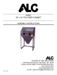
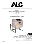
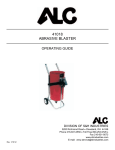
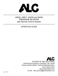
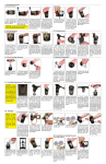
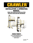
36 x 24 (SD) KNOCKDOWN CABINET BLASTER – 40393 36 x 24 (DD) KNOCKDOWN CABINET BLASTER – 40394 48 X 24 (DD) KNOCKDOWN CABINET BLASTER – 40395 INSTRUCTIONS AND ASSEMBLY MANUAL Please read instructions completely before starting any assembly. DIVISION OF S&H INDUSTRIES 5200 Richmond Road Cleveland, OH 44146 Phone 216-831-0550 Toll Free 800-253-9726 Fax 216-831-9573 www.shindustries.com E-mail: [email protected] Rev. 1/19/12 40393, 40394, 40395Assembly Instructions Page 2 WARNING! Do not use an ALC Pressure Blaster until you have read this manual and you understand its contents and warnings. These warnings are included for the health and safety of the operator and those in the immediate vicinity. Keep this manual for future reference. Dust created by power sanding, sawing, grinding, drilling, and other construction activities may contain chemicals known to cause cancer, birth defects or other reproductive harm and respiratory illnesses. Some examples of the chemicals include: Lead from lead based paints Crystalline silica from bricks, cement and other masonry products Arsenic and chromium from chemically-treated lumber Your risk from these exposures varies, depending on how often you do this type of work. To reduce your exposure to these chemicals: Work in a ventilated area, and work with approved safety equipment, such as those dust masks that are specially designed to filter out microscopic particles. Abrasive blasting produces harmful dust. Everyone in the blasting area must wear a properly fitted and properly maintained NIOSH-approved supplied-air respirator. SILICOSIS AND OTHER DUST WARNINGS: Breathing dust from silica sand may cause silicosis, a fatal lung disease. Breathing dust during blasting operations may also cause asbestosis and/or other serious or fatal diseases. A NIOSH-approved, well-maintained air-supplied abrasive blasting respirator must be used by anyone blasting, anyone handling or using media containing toxic substances or media with more than point one percent (.001) free crystalline silica and anyone in the area of the dust. Harmful dust can remain suspended in the air for long periods of time after blasting has ceased, causing serious injury or death. Before removing respirator, use an air monitoring instrument to determine if atmosphere is safe to breathe. Contact local OHSA or NIOSH office to determine the proper respirator for your particular application. Supplied-Air respirators do not remove or protect against carbon monoxide (CO) or any other toxic gas. Use a carbon monoxide removal device and monitoring device with the respirator to ensure grade D quality air. Follow all applicable OSHA standards and OSHA regulation 1910.134 (d). 40393, 40394, 40395Assembly Instructions Page 3 WARNING! Disconnecting hose while Unit is under pressure could cause serious injury or death. Use safety lock pins and safety cables in all coupling connections to help prevent hose couplings from accidental disconnection. If twist-on type air hose couplings are used, they must be secured by safety lock pins or wires to prevent accidental disconnection while under pressure. Hose disconnection while under pressure could cause serious injury. PRESSURE BLASTER SAFETY PROCEDURES CAUTION: READ THESE SAFETY PROCEDURES IN THEIR ENTIRETY – PARTS OF THE OPERATING INSTRUCTIONS ARE WITHIN THESE WARNINGS. These procedures are not intended to be exhaustive due to the many variables in the abrasive blasting field. Therefore, we INSIST that the hands, ears, mouth, nose and eyes be covered with appropriate safety protection at all times. ADDITIONAL WARNINGS! CAUTION MUST BE EXERCISED BY USER AT ALL TIMES 1. Do not exceed maximum working pressure of 110 PSI. Failure to keep maximum working pressure below 110 PSI can cause the blast machine to burst, causing death or serious injury. 2. Everyone in the blast area including the equipment operator should correctly use and maintain a NIOSH approved air supplied respirator, even after blasting has ceased. Harmful dust can remain suspended in the air for long periods of time after blasting has ceased causing injury or death. 3. Before using the pressure blaster: Put on eye protection, gloves, and NIOSH-approved respirator. Always wear these protective items when operating and while servicing your abrasive blaster. A well maintained air supplied blasting respirator must be used by anyone blasting. 4. For safe operation, perform recommended preventive maintenance on blaster cabinet, and accessories. Replace all worn parts before they fail. Immediate replacement of worn components is required. Failure to replace worn components could result in exposing the operator or bystanders to high speed media and compressed air, causing serious injury. 5. Do not use corrosive materials of any type in unit. Use only clean, dry media. 6. Do not splice abrasive hose. The splice will wear out quickly and may violently spray media over the surrounding area. A worn blast hose could suddenly fail. Couplings 40393, 40394, 40395Assembly Instructions Page 4 and nozzle holders may not adequately grip worn hose, causing them to blow off under pressure. Compressed air and abrasive escaping from a burst hose, or disconnected coupling or nozzle holder, could cause severe injury. 7. Always place the machine so that the outlet is pointed away from any objects or persons. Stand clear of the path of exiting abrasive. It may come out at high velocity. Impact from exiting abrasive could cause severe injury. 8. Static electricity can be created by the use of this equipment. Do not use within fifty feet of any explosive, potentially explosive substances, or their vapors as an explosion can occur 9. Do not use this equipment in any area that might be considered hazardous or where flammable gases or liquids are present. Failure to do so may cause an explosion resulting in serious injury. WARNING! The threads on the nozzle holder must be inspected each time the nozzle is secured to the holder. Check the threads for wear, and make sure nozzle holder securely grips the nozzle. The nozzle washer must also be inspected for wear. Worn nozzle washers cause thread erosion. A loose-fitting nozzle may eject from the holder under pressure and could cause severe injury. 40393, 40394, 40395Assembly Instructions Page 5 HOPPER PANEL ASSEMBLY INSTRUCTIONS IMPORTANT: APPLY A UNIFORM BEAD OF CAULK ON ALL FLANGES AND AROUND BOLT HOLES. AFTER FINAL ASSEMBLY, RECAULK SEAMS IF NECESSARY. Assemble the front/rear hopper panel to the right/left side hopper panel with front/rear hopper flanges to inside of side hopper panels. Secure all hopper panels by lining up panel holes. Secure hopper panels with 1/4-20 x 1/2” bolt. Secure with 1/4-20 hex nut from inside. Assemble hopper drain cap to bottom of hopper panels with drain cap flanges on outside. Secure with 1/4-20 x 1/2” bolts from outside. Secure with 1/4-20 hex nuts from inside. REAR/SIDE PANEL TO HOPPER PANEL ASSEMBLY IMPORTANT: APPLY A UNIFORM BEAD OF CAULK ON ALL FLANGES AND AROUND BOLT HOLES. AFTER FINAL ASSEMBLY, RECAULK SEAMS IF NECESSARY. Assemble rear/side panels to hopper assembly with bottom flange of rear/side panels to outside of hopper flanges. Assemble right side panel to right side hopper panel. Assemble side flange of rear panel to outside of side panel flange. Secure with 1/4-20 x 1/2” bolt from outside in two places per 40393, 40394, 40395Assembly Instructions Page 6 side. Secure with 1/4 USS washer from inside in two places per side until all panels are secured. Secure all panels using above-mentioned hardware. FRONT/TOP PANEL TO CABINET ASSEMBLY IMPORTANT: APPLY A UNIFORM BEAD OF CAULK ON ALL FLANGES AND AROUND BOLT HOLES. AFTER FINAL ASSEMBLY, RECAULK SEAMS IF NECESSARY. Assemble top panel to rear/side panels with angled lip to the front. Place top panel to the outside of rear/side panels. Assemble the front panel to hopper/side panels with bottom flange of front panel to the outside. Use top hole on each side of front panel for attachment to side panels. Use 1/4-20 x 1/2” bolts from outside. Secure with 1/4-20 hex nuts from inside. Use the same hardware for top panel assembly. TOP/SIDE DOOR PANEL TO CABINET ASSEMBLY Assemble door panel to cabinet with door panel hinges to the outside of top panel. Secure with 1/420 hex nuts from inside. Assemble side door panel by placing side door bolts through holes on right side panel from outside. Secure with 1/4-20 hex nuts from inside. Assemble handle to side door with T-handle to the outside of side door. Line up holes on T-handle with holes on side door. Secure with 8-32 screws from outside. Secure with 8-32 hex nuts from inside. Assemble cam to stem of Thandle from inside. Secure with two 8-32 hex nuts. Adjusting may be needed to cam so that side door closed fully. Use 1/2 x 1 PSA foam on the inside of the door panel. 40393, 40394, 40395Assembly Instructions Page 7 WINDOW LENS/FRAME ASSEMBLY Use 1/2 x 1 PSA foam 24” long horizontally both top and bottom of door panel. Use 1/2 x 1 PSA foam 10” long vertically on both sides of door panel. Place 1/4-20 x 1” bolt through door panel from inside. Secure with 1/4-20 hex nut from outside. Place window lens underlay on top of PSA foam. Place acrylic window lens on top of underlay. Place window lens frame to outside of acrylic window lens. Use 1/4 USS washers outside of window frame on 1/4-20 x 1” bolts. Same in four places. Secure with 1/4-20 hex nuts from outside. Same in four places. Use 1/2 x 1” PSA foam on outside of top door. Use 48-1/2” of foam horizontally. Use 12-1/2” of foam vertically. Place foam on the surrounding outer surface. Installation will be made when closing top door to cabinet. HASP TO CABINET ASSEMBLY Assemble hasp to outside of front panel of cabinet. Close top door tightly against cabinet. Place latch to door hole. Hold latch handle straight out (90 from cabinet front). Mark holes for placement. Drill 11/64” holes in two places. Secure with two 8-32 screws from outside. Secure with two 8-32 hex nuts from inside. 40393, 40394, 40395Assembly Instructions Page 8 LEGS/FLOOR SUPPORT TO CABINET ASSEMBLY Note: Place cabinet on surface with rear panel facing downward. Assemble vertical legs to bottom corners of cabinet with similar legs to outside of cabinet. Holes on legs will match holes on cabinet. Use bottom two holes on each corner of cabinet for leg assembly. Secure with 1/4-20 x 1/2” bolts from outside of legs. Secure with 1/4-20 hex nuts from inside of cabinet. Assemble floor support front/rear to inside of vertical legs. Secure with 1/4-20 x 1/2” bolts from outside and 1/4-20 hex nuts from inside. Assemble bottom side support to inside of front/rear floor support. Secure with 1/4-20 x 1/2” bolts from outside and 1/4-20 hex nuts from inside. Use same assembly to both bottom side supports. 40393, 40394, 40395Assembly Instructions Page 9 ASSEMBLY DIAGRAM FOR OPTIONAL DUST COLLECTOR Below is the component breakdown for ALC 100 CFM dust collector. The dust collector is assembled and ready for use. Dust collector hose is located in the bottom drum of the collector and must be removed and attached to dust collector and cabinet. Item No. 1 1 2 3 3 4 5 Part No. 11568 10759 11637 11012 11008 40267 SM Description Cap for dust collector Protective edging Switch Connector Electric cord Filter bag n/a Item No. 6 7 8 9 10 11 12 Part No. 11567 40287 11602 11564P 11565P 11575 Description Motor screen Vacuum motor Motor support bracket Top drum n/a Bottom drum Dust Collector Hose 2 ¼” x 6” 40393, 40394, 40395Assembly Instructions Page 10 Cabinet Parts # 1 2 3 4 5 6 7 8 9 10 11 12 13 14 15 16 17 18 19 20 21 22 23 24 25 26 27 28 29 30 31 32 33 34 35 36 37 38 39 40 41 42 43 P/N 11601 40343 40251 4025300 11109 10904 11580 11610 11611 11604 12800 11596 40248 40240 11605 11595 11606 10188 12556 10201 10199 10218 11160 11161 11594 40235 12002 11971 12003 12004 12005 12006 DESCRIPTION RIGHT SIDE PANEL LEFT SIDE PANEL REAR PANEL FRONT PANEL DOOR PANEL SIDE DOOR (OPTIONAL) TOP PANEL FRONT/REAR HOPPER PANEL RIGHT SIDE HPPER PANEL LEFT SIDE HOPPER PANEL HOPPER DRAIN CAP ½ X 1 PSA FOAM PICKUP TUBE ACRYLIC WINDOW LENS WINDOW LENS UNDERLAY HASP SHEET METAL PLUG GRATE T HANDLE FOR SIDE DOOR (DOUBLE DOOR) CAM FOR T HANDLE (DOUBLE DOOR) ECONOMY SIPHON GUN (TRIGGER) ECONOMY SIPHON GUN (OPTIONAL FOOT PEDAL) PRESSURE HOSE (FOOT PEDAL) GLOVES 24” X 6” GLOVE CLAMP SIPHON HOSE GUN PRESSURE HOSE ¼” PIPE COUPLING ½ USS WASHER #10 X 5/8 SELF-TAPPING SCREW HEAD ¼-20 HEX NUT ¼-20 X 1 BOLT ¼ USS WASHER 8-32 X ½ SCREW 8-32 HEX NUT FOOT PEDAL (OPTIONAL) LIGHT KIT WINDOW LENS FRAME CAULK RIGHT FRONT/LEFT REAR LEG LEFT FRONT/RIGHT REAR LEG SIDE LEG SUPPORT FRONT/REAR LEG SUPPORT QTY. 1 EA 1 EA 1 EA 1 EA 1 EA 1 EA 1 EA 1 EA 1 EA 1 EA 1 EA 19’/23’/25’ 1 EA 1 EA 1 EA 1 EA 1 EA 1 EA 1 EA 1 EA 1 EA 1 EA 1 EA 1 EA 2 EA 1 EA 1 EA 1 EA 1 EA 103, 106, 132 17, 22, 25 4 EA 4 EA 6 EA 8 EA 1 EA 1 EA 1 EA 1 EA 2 EA 2 EA 2 EA 2 EA 40393, 40394, 40395Assembly Instructions Page 11 Cabinet Panel / MISC. Parts 12001 11992 11993 11994 11995 11996 11997 11998 11999 12000 11580 12002 12007 12008 12009 12010 12011 12012 12013 12014 12015 11582 RIGHT SIDE PANEL LEFT SIDE PANEL REAR PANEL FRONT PANEL DOOR PANEL TOP PANEL FRONT/REAR HOPPER PANEL RIGHT SIDE HOPPER PANEL LEFT SIDE HOPPER PANEL HOPPER DRAIN CAP GRATE RIGHT SIDE PANEL LEFT SIDE PANEL REAR PANEL FRONT PANEL DOOR PANEL TOP PANEL FRONT/REAR HOPPER PANEL RIGHT SIDE HOPPER PANEL LEFT SIDE HOPPER PANEL HOPPER DRAIN CAP GRATE 36 36 36 36 36 36 36 36 36 36 36 48 48 48 48 48 48 48 48 48 48 48 X 24 X 24 X 24 X 24 X 24 X 24 X 24 X 24 X 24 X 24 X 24 X 24 X 24 X 24 X 24 X 24 X 24 X 24 X 24 X 24 X 24 X 24 DOUBLE DOUBLE DOUBLE DOUBLE DOUBLE DOUBLE DOUBLE DOUBLE DOUBLE DOUBLE DOUBLE DOUBLE DOUBLE DOUBLE DOUBLE DOUBLE DOUBLE DOUBLE DOUBLE DOUBLE DOUBLE DOUBLE DOOR DOOR DOOR DOOR DOOR DOOR DOOR DOOR DOOR DOOR DOOR DOOR DOOR DOOR DOOR DOOR DOOR DOOR DOOR DOOR DOOR DOOR 40393, 40394, 40395Assembly Instructions Page 12 REPLACEMENT PARTS AND OPTIONAL ACCESSORIES Part No. S1599 S1555 S1556 40142 155513 155512 40345 40370 REPLACEMENT PARTS Description Blast gun with 1/4” nozzle, 1/8” air jet 13/64” Steel nozzle (gold), 7 CFM @ 80 PSI** Nozzle Kit 1/4” Steel nozzle (silver), 15 CFM @ 80 PSI Nozzle Kit 5/64” Air jet (gold)** Inc. in Nozzle Kit 1/8” Air jet (silver) Inc. in Nozzle kit Air jet washer 13/64” Ceramic nozzle, 7 CFM @ 80 PSI** Nozzle Kit 1/4” Ceramic nozzle, 15 CFM @ 80 PSI** Nozzle Kit Siphon head 7’ x 3/8” hose with 90 molded end ** = optional, not included 40393, 40394, 40395Assembly Instructions Page 13 Coal Slag Coal Slag is used when paint and rust has to be removed from steel, such as car bodies, tanks or heavy machinery. Coal Slag is faster cutting, can be re-used, is moisture free, and will not pack or absorb moisture. (25 Lb. container) Steel Grit Steel grit is extremely fast cutting on rusty metal and hard to remove paint. Steel Grit is popular because it leaves a very smooth finish. It is also comparable in price to most other specialty abrasives. Steel Grit is recommended in reclaim systems or cabinets. (25 Lb. container) Glass Bead Glass Bead is used in creating a satin or matte finish. Glass Bead is recommended in reclaim systems or cabinets. (25 Lb. container) Aluminum Oxide Aluminum Oxide is a high quality abrasive that is sharper than sand (not recommended) and cuts twice as fast as sand. It leaves a smooth textured finish with no pits or burrs. Aluminum Oxide is rougher than glass bead and can be used over and over again. It is one of the most economical abrasives you can use in any reclaim systems or cabinets. (4/25 Lb. container) Plastic Grit Primarily used to strip aluminum and fiberglass. Great for stripping paint, light oxidation and surface rust. Recommended for use in blast cabinets because it creates very little dust. Works quickly, last a long time and increases visibility within the cabinet. (10 Lb. container) Walnut Shells Walnut shells are recommended for use on “soft” surfaces such as aluminum, glass, wood, and other areas where no pitting is desired. Leaves a smooth, dull finish. (10 Lb. container) 40393, 40394, 40395Assembly Instructions Page 14 TROUBLESHOOTING TIPS PROBLEM/CAUSE Surging of blast flow: Air pressure too low Too much media POSSIBLE SOLUTION Check pressure gauge on compressor Excessive media consumption: Media valve open too far Air pressure too low Close slightly Check pressure gauge on compressor Clogging and plugging of blast flow: Debris in media Media size too large Nozzle plugs Nozzle plugs Wet media Purge and screen Use smaller grit size Use larger nozzle Adjust media valve 40200 Dry media, drain water from air Moisture in abrasive media: Wet media Water in air Water in tank Change or use dry media Drain water from air lines Empty, dry out and refill Humid weather: Moderate humidity Moderate humidity High humidity Keep media as dry as possible Use drier or moisture separator Avoid that period of use if possible Overtaxed compressor: Compressor too small Nozzle size too large Too many leaks in plumbing Holes in abrasive hose Air filter on compressor plugged Restrict time used Use smaller size Seal and tighten plumbing Replace hose Clean Lack of air pressure: Compressor too small Supply valves not on full position Nozzle size too large Leaks in plumbing Holes in abrasive hose Air filter on compressor plugged Urethane gasket worn or dirty Use smaller nozzle Open valves Use smaller size Seal and tighten plumbing Replace hose Clean filter Clean or replace gasket Lack of abrasive flow: Blaster tank empty Moisture in media Not enough air pressure Abrasive hose kinked Debris in media Fill tank (6” from top) Dry media Check system Straighten hose Clean or screen media 40393, 40394, 40395Assembly Instructions Page 15 Disclaimer of Warranties. S & H Industries, Inc. ("Seller") makes no warranties with respect to any goods delivered to Buyer or users except as specifically set forth within this manual. S & H INDUSTRIES, INC. MAKES NO IMPLIED WARRANTIES OF MERCHANTABILITY OR FITNESS FOR A PARTICULAR PURPOSE WITH RESPECT TO ANY OF THE GOODS, AND S & H INDUSTRIES, INC. EXPRESSLY DISCLAIMS ANY IMPLIED WARRANTIES AGAINST INFRINGEMENT. S & H INDUSTRIES, INC. WARRANTIES SHALL NOT APPLY TO ANY DAMAGE OR NON-CONFORMITY RESULTING FROM THE NEGLIGENT OF IMPROPER ASSEMBLY OR USE OF ANY GOODS BY USERS OR BUYER OR ITS EMPLOYEES OR AGENTS, OR FROM ALTERATION OR ATTEMPTED REPAIR BY ANY PERSON OTHER THAN S & H INDUSTRIES, INC. ALL USED, REPAIRED, MODIFIED OR ALTERED ITEMS ARE PURCHASED AS-IS AND WITH ALL FAULTS. Indemnification Agreement. Buyer agrees, to the fullest extent permitted by the law, to fully indemnify, hold harmless, and defend Seller, its parent, subsidiary, and affiliated companies, its owners, officers, directors, employees, agents, representatives and insurers (collectively, “Indemnities”) from and against any and all claims, demands, suits, damages, judgments of sums of money, losses and expenses, including but limited to attorney’s fees and costs (collectively “referred to herein as “Claims”) arising out of or resulting from any bodily injury, sickness, disease or death or injury to or destruction of tangible property, arising out of or resulting from the use, sale or distribution of any and all products purchased from Seller by Buyer, regardless of whether or not such claim arises in whole or in part out of Seller’s alleged fault, including but not limited to Seller’s negligence, strict liability, products liability, breach of warranty or any other act or omission. Buyer expressly waives any and all immunity from suit by Seller, its parent, subsidiary, and affiliated companies, and its owners, officers, directors, employees, agents, representatives and insurers, by operation of any workers’ compensation law or statute. By purchasing from S & H Industries, Inc., Buyer acknowledges and represents that Buyer has read, fully understands and agrees to the Indemnification provisions set forth above. LIMITED WARRANTY S & H Industries Inc. warrants this product to be free from defects in materials or workmanship for two years after the date of original purchase. If the product should become defective within that warranty period, we will repair or replace it (at our option) free of charge including return transportation to you provided you deliver it prepaid to S & H Industries Inc., 5200 Richmond Road, Bedford Hts., Ohio 44146. This warranty does not include damage resulting from accident, abuse or misuse of the product. Nor does it apply to parts subject to abrasive wear, i.e., nozzles, air jets, seal blocks, valves, hose connections and hoses. Implied warranties including those of merchantability and fitness for a particular purpose are excluded to the extent permitted by law, and any and all implied warranties are excluded. This is the exclusive remedy and liability for consequential damages under any and all warranties are excluded to the extent exclusion is permitted by law.