1
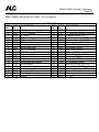
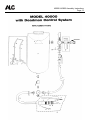
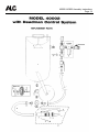
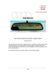
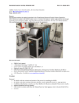
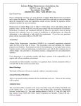
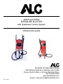
40000 and 40002 PRESSURE BLASTER with Deadman Control System OPERATION GUIDE DIVISION OF S&H INDUSTRIES 5200 Richmond Road Cleveland, OH 44146 Phone 216-831-0550 Toll Free 800-253-9726 Fax 216-831-9573 www.shindustries.com E-mail: [email protected] Rev. 1/19/12 40000 & 40002 Assembly Instructions Page 2 WARNING! Do not use an ALC Pressure Blaster until you have read this manual and you understand its contents and warnings. These warnings are included for the health and safety of the operator and those in the immediate vicinity. Keep this manual for future reference. Dust created by power sanding, sawing, grinding, drilling, and other construction activities may contain chemicals known to cause cancer, birth defects or other reproductive harm and respiratory illnesses. Some examples of the chemicals include: Lead from lead based paints Crystalline silica from bricks, cement and other masonry products Arsenic and chromium from chemically-treated lumber Your risk from these exposures varies, depending on how often you do this type of work. To reduce your exposure to these chemicals: Work in a ventilated area, and work with approved safety equipment, such as those dust masks that are specially designed to filter out microscopic particles. Abrasive blasting produces harmful dust. Everyone in the blasting area must wear a properly fitted and properly maintained NIOSH-approved supplied-air respirator. SILICOSIS AND OTHER DUST WARNINGS: Breathing dust from silica sand may cause silicosis, a fatal lung disease. Breathing dust during blasting operations may also cause asbestosis and/or other serious or fatal diseases. A NIOSH-approved, well-maintained air-supplied abrasive blasting respirator must be used by anyone blasting, anyone handling or using media containing toxic substances or media with more than point one percent (.001) free crystalline silica and anyone in the area of the dust. Harmful dust can remain suspended in the air for long periods of time after blasting has ceased, causing serious injury or death. Before removing respirator, use an air monitoring instrument to determine if atmosphere is safe to breathe. Contact local OHSA or NIOSH office to determine the proper respirator for your particular application. Supplied-Air respirators do not remove or protect against carbon monoxide (CO) or any other toxic gas. Use a carbon monoxide removal device and monitoring device with the respirator to ensure grade D quality air. Follow all applicable OSHA standards and OSHA regulation 1910.134 (d). 40000 & 40002 Assembly Instructions Page 3 ASSEMBLY INSTRUCTIONS NOTE: Refer to diagrams on pages 14 and 15 when assembling. 1. Attach wheel assemblies to wheel support as shown in inset #1 (p. 15). Do not tighten nut snugly against wheel hub, as some movement is required to allow free rolling of wheels. Tighten hex nut directly against wheel support housing to lock wheel assembly in place. 2. Abrasive regulator valve has been preassembled and attached to the bottom of the tank. Pipe dope has been used on all fittings for positive sealing. Apply pipe dope on the bottom of the plumbing. Connect hose assemblies as shown in illustration with enclosed hose stems and hose clamps. 3. Attach abrasive hose and air by-pass hose to tank base. Proceed with assembly of air intake, choke valve, and pressure gauge assembly as shown in diagram. Optional air filter assembly as shown in diagram should be attached during this step. Manufacturer recommends the use of pipe dope on all fittings for positive sealing. Several subassemblies have been completed at the factory for your convenience. Be certain all pipe fittings and hose clamps are tight before using blaster. WARNING! Disconnecting hose while Unit is under pressure could cause serious injury or death. Use safety lock pins and safety cables in all coupling connections to help prevent hose couplings from accidental disconnection. If twist-on type air hose couplings are used, they must be secured by safety lock pins or wires to prevent accidental disconnection while under pressure. Hose disconnection while under pressure could cause serious injury. 4. The Deadman Valve Assembly has been preassembled and attached to the abrasive hose. It allows single-handed operation with safety shut-off when operator’s hand is removed or valve is dropped. (Do not over-tighten retainer nut against ceramic nozzle. Excessive tightening may cause damage to nozzle.) IMPORTANT: The 40164/40165 sealing block/nut and bolt assembly must be adjusted after inserting ceramic nozzle. Note: The Deadman Valve is adaptable to any blaster using 1/2” I.D. blast hose. Inspect and replace nozzle washer as needed or when replacing nozzles. 5. Recheck all pipe fittings and hose clamps to ensure they are securely tightened. 40000 & 40002 Assembly Instructions Page 4 PRESSURE BLASTER SAFETY PROCEDURES CAUTION: READ THESE SAFETY PROCEDURES IN THEIR ENTIRETY – PARTS OF THE OPERATING INSTRUCTIONS ARE WITHIN THESE WARNINGS. These procedures are not intended to be exhaustive due to the many variables in the abrasive blasting field. Therefore, we INSIST that the hands, ears, mouth, nose and eyes be covered with appropriate safety protection at all times. ADDITIONAL WARNINGS! CAUTION MUST BE EXERCISED BY USER AT ALL TIMES 1. Do not place fingers, any body parts or any components in the filler plug seal area when the blast machine is being pressurized. Failure to keep body parts from the filler plug area will result in serious injury. 2. Do not exceed maximum working pressure of 110 PSI. Failure to keep maximum working pressure below 110 PSI can cause the blast machine to burst, causing death or serious injury. 3. Everyone in the blast area including the equipment operator should correctly use and maintain a NIOSH-approved air-supplied respirator, even after blasting has ceased. Harmful dust can remain suspended in the air for long periods of time after blasting has ceased causing injury or death. 4. Before using the pressure blaster: Put on safety glasses, gloves, and NIOSH-approved respirator. Always wear these protective items when operating and while servicing your abrasive blaster. While a protective hood is provided to help protect you from flying particles as you use the machine, the hood does not provide protection from air borne particles. A well maintained air supplied blasting respirator must be used by anyone blasting. 5. Use thick gloves with gauntlets to protect your hands. 6. Use backboards to prevent overspray from hitting someone or something else because the dust will travel a long distance. Blast in a large open area to minimize abrasive accumulation in surrounding areas. 7. Do not pull media tank around by the abrasive hose or let tank fall over as a fitting may break rendering the machine unsafe. Media and air under 110 PSI have a very high destructive force. Never leave a pressurized machine unattended. If an emergency occurs, such as a burst blast hose, shutdown the machine immediately. 40000 & 40002 Assembly Instructions Page 5 8. Drain air out of tank through the inlet valve and disconnect power before maintenance cleaning of any kind. When removing nozzle, caution must be exercised as air pressure may still be in the hose if the nozzle is plugged. 9. For safe operation, perform recommended preventive maintenance on blaster tank, remote unit and accessories. Replace all worn parts before they fail. Immediate replacement of worn components is required. Failure to replace worn components could result in exposing the operator or bystanders to high speed media and compressed air, causing serious injury. 10. Do not use corrosive materials of any type in unit. Use only clean, dry media. 11. Do not splice abrasive hose. The splice will wear out quickly and may violently spray media over the surrounding area. A worn blast hose could suddenly fail by bursting. Couplings and nozzle holders may not adequately grip worn hose, causing them to blow off under pressure. Compressed air and abrasive escaping from a burst hose, or disconnected coupling or nozzle holder, could cause severe injury. 12. Welding, grinding, or drilling on the blast machine could weaken the vessel. Compressed air pressure could cause a weakened blast machine to rupture, resulting in death or serious injury. 13. Always place the machine so that the outlet is pointed away from any objects or persons. Stand clear of the path of exiting abrasive. It may come out at high velocity. Impact from exiting abrasive could cause severe injury. 14. Static electricity can be created by the use of this equipment. Do not use within fifty feet of any explosive, potentially explosive substances, or their vapors as an explosion can occur. 15. Do not use this equipment in any area that might be considered hazardous or where flammable gases or liquids are present. Failure to do so may cause an explosion resulting in serious injury. 16. Do not overfill tank with media. Do not fill to within 6 inches from top of the tank. 40000 & 40002 Assembly Instructions Page 6 OPERATING INSTRUCTIONS OPERATING TECHNIQUE: 1. Connect air hose to air inlet valve. Manufacturer recommends using minimum incoming air hose of 1/2” I.D. Using an air hose smaller than 1/2” I.D. will restrict air volume and result in poor unit operation. Prior to injection of air, be certain air inlet valve and nozzle valve are in the OFF position. With Deadman Valve closed and closure plug in the UP position, open air inlet valve allowing air to pressurize. Operating range of unit is 40 to 110 PSI. Note: For proper nozzle selection, refer to nozzle selection chart below. After proper nozzle selection, insert nozzle into retainer base. Set against washer and slide retainer nut over nozzle and tighten by hand. 2. The Pressure Blaster is equipped with a unique semi-automotive pull-up closure design. Manufacturer recommends a fine grade abrasive with granular size similar to that of table salt. This assures proper flow and reduces the possibility of nozzle obstruction. When ready to pressurize container, pull up closure and turn on incoming air. The internal air pressure will seal the closure. 3. With the blaster pressurized and abrasive flow regulator valve at base of unit closed, open choke valve allowing air to flow through by-pass hose to base of the unit. Then holding the abrasive hose by nozzle retainer housing with nozzle directed away from unit and operator, quickly squeeze the Deadman Valve fully open and adjust the regulator valve at base of tank to bleed the abrasive into air flow. Slowly open regulator valve until abrasive material is slightly visible. Once the regulator flow valve is adjusted to the desired setting, further adjustment should only be required when changing grade of abrasive material or when a nozzle with a different I.D. is used. For best performance, the Deadman Valve should be opened and closed quickly. Note: The choke valve located at the rear of the tank on the by-pass air line must always be open during blasting. 40000 & 40002 Assembly Instructions Page 7 WARNING! All persons except for the equipment user must stay clear of the blast machine. The user may pressurize or depressurize the machine at any time. The noise generated by the sudden release of compressed air while the machine is pressurized or depressurized may startle bystanders, and may vent abrasive under pressure. Either condition could result in injury. NOZZLE SELECTION CHART PART NO. NOZZLE I.D. CFM PSI BLASTING AREA ABRASIVE SQ. FT./MIN. USAGE/HR. 40067 3/32” 7 80 1/2 100 lbs. 40068 1/8” 15 80 1 to 1-1/2 150 lbs. 40069 5/32” 25 80 2 to 2-1/2 200 lbs. 40070 3/16” 40 80 3 to 3-1/2 300 lbs. 40071 1/4” 80 80 4 to 4-1/2 500 lbs. 40072 5/16” 125 80 5 to 6 800 lbs. NOTE: Blast area coverage per minute and abrasive consumption are approximate guidelines. Abrasive material and surface blasted may alter coverage and consumption rates. Furthermore, for each 50 feet of blast hose there will be a 5 PSI pressure drop. WARNING! The threads on the nozzle holder must be inspected each time the nozzle is secured to the holder. Check the threads for wear, and make sure nozzle holder securely grips the nozzle. The nozzle washer must also be inspected for wear. Worn nozzle washers cause thread erosion. A loose-fitting nozzle may eject from the holder under pressure and could cause severe injury. 40000 & 40002 Assembly Instructions Page 8 AIR COMPRESSOR RECOMMENDATION: To permit efficient operation of your air compressor, follow these guidelines: 1. Use a smaller size nozzle and air jet to control the demand of air. 2. Do not blast continuously. Stop blasting operation periodically to allow the compressor to cool. No compressor is designed to constantly run at full RPM. Use 70% of the rated output. 3. Use a minimum 1/2” air hose or metal piping from your air compressor to the blaster. If your compressor is creating an excessive amount of moisture, we recommend using a water trap or a moisture separator. 4. The air compressor should be drained at the bottom of the supply tank through a drain valve and should be blown down daily. It is not unusual to drain three or four gallons of water from the supply tank on a high humidity day. An additional supply tank will help. 5. Keep dust and media created by blasting away from the air compressor unit. Observe maximum air pressure requirements for the blaster and either set your compressor to run within these limits or use a pressure regulator valve to reduce the air pressure to the appropriate range. ABRASIVE (MEDIA) USAGE: 1. If moisture is in the media it will eventually damage the blaster tank or plug the system. Keep the media and compressor air dry to avoid this problem. 2. If media is moist, screen it and dry it before using. 3. Do not leave media in the tank after blasting because it can absorb moisture and impair blasting performance. 4. Store media in a dry place; keep media off the ground or concrete floors. Put it on a wooden skid. 5. If the humidity is excessively high, it may not be advisable to blast at that time. 6. Consider using different grades or different types of media to prevent nozzle clogging due to high moisture content. 7. Do not use sand. 40000 & 40002 Assembly Instructions Page 9 Warning! Do not fill the pressure vessel to within six (6) inches of the top of the vessel. If a hose is accidentally disconnected during use media spray may occur. Material to Be Cleaned Steel vats Auto fenders Brick and block Steel cabinets Truck bodies Glass etching Wood ABRASIVE AND PRESSURE GUIDE Air Pressure Abrasive 100-125 psi Black magnum 10898 50-80 psi Black magnum 10898 80-125 psi Black magnum 10898 80-125 psi Black magnum 10898 100-125 psi Black magnum 10898 50-70 psi Glass beads Silicon carbide 50-70 psi Nut shells Glass beads Grit Size 30/50 20/40 80/120 20/40 30/50 20/40 30/50 20/40 30-50 20/40 30/40 100 14/30 30/40 See respiratory related WARNINGS at the beginning of the manual. Coal Slag # 40093 Coal Slag is used when paint and rust has to be removed from steel, such as car bodies, tanks or heavy machinery. Coal Slag is faster cutting, can be re-used, is moisture free, and will not pack or absorb moisture. (25 Lb. container) Steel Grit #40109 Steel grit is extremely fast cutting on rusty metal and hard to remove paint. Steel Grit is popular because it leaves a very smooth finish. It is also comparable in price to most other specialty abrasives. Steel Grit is recommended in reclaim systems or cabinets. (25 Lb. container) Glass Bead #40105 Glass Bead is used in creating a satin or matte finish. Glass Bead is recommended in reclaim systems or cabinets. (25 Lb. container) Aluminum Oxide #40098 Aluminum Oxide is a high quality abrasive that is sharper than sand (not recommended) and cuts twice as fast as sand. It leaves a smooth textured finish with no pits or burrs. Aluminum Oxide is rougher than glass bead and can be used over and over again. It is one of the most economical abrasives you can use in any reclaim systems or cabinets. (4/25 Lb. container) Plastic Grit #40110 Primarily used to strip aluminum and fiberglass. Great for stripping paint, light oxidation and surface rust. Recommended for use in blast cabinets because it creates very little dust. Works quickly, last a long time and increases visibility within the cabinet. (10 Lb. container) Walnut Shells #40112 Walnut shells are recommended for use on “soft” surfaces such as aluminum, glass, wood, and other areas where no pitting is desired. Leaves a smooth, dull finish. (10 Lb. container) 40000 & 40002 Assembly Instructions Page 10 TROUBLESHOOTING TIPS PROBLEM/CAUSE POSSIBLE SOLUTION Surging of blast flow: Air pressure too low Too much media Check air pressure gauge on compressor Adjust media valve 40200 Excessive media consumption: Media valve open too far Air pressure too low Close slightly Check pressure gauge on compressor Clogging and plugging of blast flow: Debris in media Media size too large Nozzle plugs Nozzle plugs Wet media Purge and screen Use smaller grit size Use larger nozzle Adjust media valve 40200 Dry media, drain water from air Moisture in abrasive media: Wet media Water in air Water in tank Change or use dry media Drain water from air lines Empty, dry out and refill Humid weather: Moderate humidity Moderate humidity High humidity Keep media as dry as possible Use drier or moisture separator Avoid that period of use if possible Overtaxed compressor: Compressor too small Nozzle size too large Too many leaks in plumbing Holes in abrasive hose Air filter on compressor plugged Restrict time used Use smaller size Seal and tighten plumbing Replace hose Clean Lack of air pressure: Compressor too small Supply valves not on full position Nozzle size too large Leaks in plumbing Holes in abrasive hose Air filter on compressor plugged Urethane gasket worn or dirty Use smaller nozzle Open valves Use smaller size Seal and tighten plumbing Replace hose Clean filter Clean or replace gasket Lack of abrasive flow: Blaster tank empty Moisture in media Not enough air pressure Abrasive hose kinked Debris in media Fill tank Dry media Check system Straighten hose Clean or screen media 40000 & 40002 Assembly Instructions Page 11 MAINTENANCE WARNING! Failure to observe the following before performing any maintenance could cause serious injury or death from the sudden release of compressed air: Depressurize the blast machine. Disconnect power supply. Lockout and tagout the compressed air supply. Bleed the air supply line to the blast gun. Immediate replacement of worn components is required. Failure to replace worn components could expose the operator or bystanders to high speed media and compressed air could cause death or serious injury. Leaks around couplings and nozzle holders indicate worn or loose fitting parts. Nozzle holders and couplings that do not fit tightly on hose and nozzles that do not fit tightly in nozzle holders could disconnect while under pressure. Impact from nozzles, couplings, hoses, or abrasive, and parts disconnected while under pressure could cause severe injury. To ensure a long and efficient operational life of the Deadman Control System, it is highly recommended that the following procedures be followed: 1. Periodically (after 5-6 months of moderate use or after 10-15 hours of heavy industrial use) replace all hose adaptors that are for abrasive flow use only (Order No. 40192). 2. Replace rubber sealing block on 40166 after 7-10 hours of use to maintain proper shut-off (Order No. 40164). 3. Check abrasive hose when it begins to soften or leaks media or air around the hose or handle area. 4. Replace the nozzle when it wears to the next larger size (at this time the Venturi effect of the nozzle is inefficient). 5. Check the urethane gasket in the pull-up closure when the air leaks excessively from the opening (make sure the gasket is free from media). 40000 & 40002 Assembly Instructions Page 12 Note: Replace with genuine ALC parts – do not substitute. ITEM NO. 1 2 3 4 5 6 7 8 9 10 11 12 13 14 15 16 17 18 19 20 PART NO. 40224 40219 40221 40213 40198 40186 10935 10937 40217 40199 40192 10905 40223 40170 40196 40193 Pg. 4 40164 40165 40168 DESCRIPTION PARTS LIST ITEM NO. 21 22 23 24 0-200 psi pressure gauge 1/2” x ¼” bushing 1/2” cross 1/2” x close nipples 1/2” bronze ball valve 1/2” brass adapter Hose clamp Red by-pass hose 3/4” x ½” bushing 1/2” ball valve (pressure relieving) 1/2” hose adaptor 1/2” hose clamp 1/2” plug Nozzle base with bracket Nozzle washer Nozzle retainer nut Nozzle–see pg. 4 for size/part no. Sealing block Nut and bolt assembly Handle 25 26 27 28 29 30 31 32 33 34 35 36 37 38 39 PART NO. 11500 40207 40225 40278 40280 40228 40117 10951 10952 10953 10956 10955 10943 10705 40173 40232 40233 40166 40229 40230 DESCRIPTION Pivot tension spring 1/2” moisture separator (optional) 6” wheels (40001 only) Pressure tank only (40000) Pressure tank only (40002) Closure gasket 10’ x 1/2” I.D. abrasive hose Left handle (40000) Right handle (40000) U-brace (40000) 1/2” x 14-1/2” Axle (40000) Front leg (40000) Black caps (40000) 1/2” hubcaps (40000) Bolt and nut assy. for 40168 Axle bolt assy. (40002) Hardware package (40000 cart) Complete Deadman Handle Pressure relief valve 1/2” tee 40000 & 40002 Assembly Instructions Page 13 40000 & 40002 Assembly Instructions Page 14 40000 & 40002 Assembly Instructions Page 15 Disclaimer of Warranties. S & H Industries, Inc. ("Seller") makes no warranties with respect to any goods delivered to Buyer or users except as specifically set forth within this manual. S & H INDUSTRIES, INC. MAKES NO IMPLIED WARRANTIES OF MERCHANTABILITY OR FITNESS FOR A PARTICULAR PURPOSE WITH RESPECT TO ANY OF THE GOODS, AND S & H INDUSTRIES, INC. EXPRESSLY DISCLAIMS ANY IMPLIED WARRANTIES AGAINST INFRINGEMENT. S & H INDUSTRIES, INC. WARRANTIES SHALL NOT APPLY TO ANY DAMAGE OR NON-CONFORMITY RESULTING FROM THE NEGLIGENT OF IMPROPER ASSEMBLY OR USE OF ANY GOODS BY USERS OR BUYER OR ITS EMPLOYEES OR AGENTS, OR FROM ALTERATION OR ATTEMPTED REPAIR BY ANY PERSON OTHER THAN S & H INDUSTRIES, INC. ALL USED, REPAIRED, MODIFIED OR ALTERED ITEMS ARE PURCHASED AS-IS AND WITH ALL FAULTS. Indemnification Agreement. Buyer agrees, to the fullest extent permitted by the law, to fully indemnify, hold harmless, and defend Seller, its parent, subsidiary, and affiliated companies, its owners, officers, directors, employees, agents, representatives and insurers (collectively, “Indemnities”) from and against any and all claims, demands, suits, damages, judgments of sums of money, losses and expenses, including but limited to attorney’s fees and costs (collectively “referred to herein as “Claims”) arising out of or resulting from any bodily injury, sickness, disease or death or injury to or destruction of tangible property, arising out of or resulting from the use, sale or distribution of any and all products purchased from Seller by Buyer, regardless of whether or not such claim arises in whole or in part out of Seller’s alleged fault, including but not limited to Seller’s negligence, strict liability, products liability, breach of warranty or any other act or omission. Buyer expressly waives any and all immunity from suit by Seller, its parent, subsidiary, and affiliated companies, and its owners, officers, directors, employees, agents, representatives and insurers, by operation of any workers’ compensation law or statute. By purchasing from S & H Industries, Inc., Buyer acknowledges and represents that Buyer has read, fully understands and agrees to the Indemnification provisions set forth above. LIMITED WARRANTY S & H Industries, Inc. warrants this product to be free from defects in materials or workmanship for two years after the date of original purchase. If the product should become defective within that warranty period, we will repair or replace it (at our option) free of charge including return transportation to you provided you deliver it prepaid to S & H Industries, Inc., 5200 Richmond Road, Bedford Hts., Ohio 44146. This warranty does not include damage resulting from accident, abuse or misuse of the product. Nor does it apply to parts subject to abrasive wear, i.e., nozzles, air jets, seal blocks, valves, hose connections and hoses. Implied warranties including those of merchantability and fitness for a particular purpose are excluded to the extent permitted by law, and any and all implied warranties are excluded. This is the exclusive remedy and liability for consequential damages under any and all warranties are excluded to the extent exclusion is permitted by law.