1
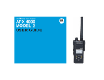
APX™ Two-Way Radios APX6000XE 1) Select/copy image from Photo Library 2) Insert and resize selected image to fill up this white area. 3) Right click on the image, “Order -> Send to Back”. APXTM 6000XE Model 1 Interactive End User Toolkit (IEUTK) APX TM 6000XE System Requirements Component Computer and processor Memory Drive Requirement Intel® Pentium® II 450MHz or faster processor. 128 megabytes (MB) of RAM or greater. CD-ROM or DVD drive. Display Super VGA (800 × 600) or higher-resolution monitor. Operating system Microsoft® Windows Vista®. Microsoft Windows XP. Microsoft Windows 2000 with Service Pack 3 (SP3). Other Microsoft Office PowerPoint 2003 or above. Adobe Flash Player 9.0 or above. Adobe Flash Player is required to run demo in this module. Please download and install Adobe Flash Player from http://get.adobe.com/flashplayer/ 2 Index APX TM 6000XE Declaration of Conformity This declaration is applicable to your radio only if your radio is labeled with the FCC logo shown below. DECLARATION OF CONFORMITY Per FCC CFR 47 Part 2 Section 2.1077(a) Responsible Party Name: Motorola Solutions, Inc. Address: 1303 East Algonquin Road, Schaumburg, IL 60196, U.S.A. Phone Number: 1-800-927-2744 Hereby declares that the product: Model Name: APX 6000XE conforms to the following regulations: FCC Part 15, subpart B, section 15.107(a), 15.107(d) and section 15.109(a) Class B Digital Device As a personal computer peripheral, this device complies with Part 15 of the FCC Rules. Operation is subject to the following two conditions: 1. This device may not cause harmful interference, and 2. This device must accept any interference received, including interference that may cause undesired operation. 3 Index APX TM 6000XE Declaration of Conformity Note: This equipment has been tested and found to comply with the limits for a Class B digital device, pursuant to part 15 of the FCC Rules. These limits are designed to provide reasonable protection against harmful interference in a residential installation. This equipment generates, uses and can radiate radio frequency energy and, if not installed and used in accordance with the instructions, may cause harmful interference to radio communications. However, there is no guarantee that interference will not occur in a particular installation. If this equipment does cause harmful interference to radio or television reception, which can be determined by turning the equipment off and on, the user is encouraged to try to correct the interference by one or more of the following measures: • Reorient or relocate the receiving antenna. • Increase the separation between the equipment and receiver. • Connect the equipment into an outlet on a circuit different from that to which the receiver is connected. • Consult the dealer or an experienced radio/TV technician for help. 4 Index APX TM 6000XE Declaration of Conformity Additional FCC Note to Users The following FCC information applies to Bluetooth radio options Model Name: MNUK6000 Description: APX 6000XE Bluetooth Option Board FCC ID: AZ489FT6000 IC: 109U-89FT6000 Conforms to the following regulations: FCC Part 15, Section 15.19, 15.21, and 15.105 Note: Changes or modifications not expressly approved by Motorola may void the users authority, as authorized by the FCC, to operate this device and should not be made. See 47 CFR Part 15.21. Information to the user. The user manual or instruction manual for an intentional or unintentional radiator shall caution the user that changes or modifications not expressly approved by the party responsible for compliance could void the user’s authority to operate the equipment. This device complies with Part 15 of the FCC Rules. Operation is subject to the following two conditions: (1) This device may not cause harmful interference, and (2) this device must accept any interference received, including interference that may cause undesired operation. See 47 CFR Part. 15.19(3). This device has been tested and found to comply with the limits of Part 15.15 of the FCC rules. Parties responsible for equipment compliance should note that the limits specified in this part will not prevent harmful interference under all circumstances. This equipment has been tested and found to comply with the limits for a Class B digital device, pursuant to part 15 of the FCC Rules. See Part 15.105b These limits are designed to provide reasonable protection against harmful interference in a residential installation. This equipment generates, uses and can radiate radio frequency energy and, if not installed and used in accordance with the instructions, may cause harmful interference to radio communications. 5 Index APX TM 6000XE Declaration of Conformity However, there is no guarantee that interference will not occur in a particular installation. If this equipment does cause harmful interference to radio or television reception, which can be determined by turning the equipment off and on, the user is encouraged to try to correct the interference by one or more of the following measures: • Reorient or relocate the receiving antenna. • Increase the separation between the equipment and receiver. • Connect the equipment into an outlet on a circuit different from that to which the receiver is connected. • Consult the dealer or an experienced radio/TV technician for help. Industry Canada (IC) Statements: This Class B digital apparatus complies with ICES-003 and Radio Standards Specification (RSS) 210. 6 Index APX TM 6000XE Copyrights/Disclaimer Computer Software Copyrights The Motorola products described in this manual may include copyrighted Motorola computer programs stored in semiconductor memories or other media. Laws in the United States and other countries preserve for Motorola certain exclusive rights for copyrighted computer programs, including, but not limited to, the exclusive right to copy or reproduce in any form the copyrighted computer program. Accordingly, any copyrighted Motorola computer programs contained in the Motorola products described in this manual may not be copied, reproduced, modified, reverseengineered, or distributed in any manner without the express written permission of Motorola. Furthermore, the purchase of Motorola products shall not be deemed to grant either directly or by implication, estoppels, or otherwise, any license under the copyrights, patents or patent applications of Motorola, except for the normal non-exclusive license to use that arises by operation of law in the sale of a product. Documentation Copyrights No duplication or distribution of this document or any portion thereof shall take place without the express written permission of Motorola. No part of this manual may be reproduced, distributed, or transmitted in any form or by any means, electronic or mechanical, for any purpose without the express written permission of Motorola. Disclaimer The information in this document is carefully examined, and is believed to be entirely reliable. However, no responsibility is assumed for inaccuracies. Furthermore, Motorola reserves the right to make changes to any products herein to improve readability, function, or design. Motorola does not assume any liability arising out of the applications or use of any product or circuit described herein; nor does it cover any license under its patent rights, nor the rights of others. 7 Index APX TM 6000XE Getting Started This Interactive End User Toolkit (IEUTK) covers the basic operation of the APX™ 6000XE portable radios. However, your dealer or system administrator may have customized your radio for your specific needs. Check with your dealer or system administrator for more information. Notations Used in This Tutorial Throughout the text in this tutorial, you will notice the use of WARNING, Caution, and Note. These notations are used to emphasize that safety hazards exist, and the care that must be taken or observed. An operational procedure, practice, or condition, etc., which may result in injury or death if not carefully observed. An operational procedure, practice, or condition, etc., which may result in damage to the equipment if not carefully observed. Note: An operational procedure, practice, or condition, etc., which is essential to emphasize. 8 Index APX TM 6000XE HOME 9 Index APX TM 6000XE Radio Parts and Controls Antenna 16-Position Select Knob* On/Off/Volume Control Knob Main Speaker Microphone Bluetooth Pairing Indicator 10 Index APX TM 6000XE Radio Parts and Controls 16-Position Select Knob* LED Indicator 3-Position A/B/C Switch Not Programmed Top (Orange) Button Emergency On/Off/Volume Control Knob Top Display 2-Position Concentric Switch Position A = Direct / Talkaround Position B = Blank 11 Index APX TM 6000XE Radio Parts and Controls Microphone Belt Clip Slot Top Side Button Zone Bank Up Push-to-Talk (PTT) Button Battery Side Button 1 Scan Side Button 2 Nuisance Delete Battery Latch 12 Index APX TM 6000XE Fleet Map Z1 Z2 Z3 Z4 Z5 1 South Band 8CALL90 CH TAC 1 SOUTH BAND FUTURE 1 2 South FG 8TAC91 TK TAC 2 SOUTH DIR FUTURE 2 3 EMERGENCY 8TAC92 PV TAC 3 EMERGENCY FUTURE 3 4 North Band 8TAC93 LS TAC 4 NORTH BAND FUTURE 4 5 North FG 8TAC94 WR TAC 5 NORTH DIR FUTURE 5 6 East Band ZONE 1 EAST BAND FUTURE 6 7 East FG ZONE 2 EAST DIR FUTURE 7 8 South Band ZONE 3 SOUTH BAND FUTURE 8 9 South FG ZONE 4 SOUTH DIR FUTURE 9 10 Central Band ZONE 5 CENTRAL BAND FUTURE 10 11 Central FG ZONE 6 CENTRAL DIR FUTURE 11 12 FP DIRECT ZONE 7 FP DIRECT FUTURE 12 13 FP NORTH ZONE 8 FP NORTH FUTURE 13 14 FP SOUTH ZONE 9 FP SOUTH FUTURE 14 15 EMS NORTH DISPATCH EMS NORTH FUTURE 15 16 EMS SOUTH PROGRAMMING EMS SOUTH FUTURE 16 13 Z6 Index APX TM 6000XE Preparing Your Radio for Use Charging the Battery To avoid a possible explosion: • DO NOT replace the battery in any area labeled “hazardous atmosphere”. • DO NOT discard batteries in a fire. The Motorola-approved battery shipped with your radio is uncharged. Prior to using a new battery, charge it for a minimum of 16 hours to ensure optimum capacity and performance. Note: When charging a battery attached to a radio, turn the radio off to ensure a full charge. Battery Charger To charge the battery, place the battery, with or without the radio, in a Motorola-approved charger. The charger’s LED indicates the charging progress; see your charger’s user guide. 14 Index APX TM 6000XE Preparing Your Radio for Use Attaching/Removing the Battery With the radio turned off, slide the battery into the radio’s frame until side latches click into place. To remove the battery, turn the radio off. Squeeze the release latches on the bottom of the battery until the battery releases from the radio. Remove the battery from the radio. Battery 15 Index APX TM 6000XE Preparing Your Radio for Use Attaching/Removing the Antenna With the radio turned off, set the antenna in its receptacle and turn clockwise to attach it to the radio. To remove the antenna, turn the antenna counterclockwise. Make sure you turn off the radio first. Antenna 16 Index APX TM 6000XE Preparing Your Radio for Use Attaching/Removing the Accessory Connector Cover The accessory connector is located on the antenna side of the radio. It is used to connect accessories to the radio. Note: To prevent damage to the connector, shield it with the connector cover when not in use. Insert the hooked end of the cover into the slot above the connector. Press downward on the cover’s top to seat it in the slot. Once in place, rotate the thumbscrew clockwise by hand until tight. To remove the accessory connector cover, rotate the thumbscrew counterclockwise until it disengages from the radio. Accessory Connector If the thumbscrew is too tight, use an Allen wrench to loosen it first. Rotate and lift the connector cover to disengage it from the radio. 17 Index APX TM 6000XE Preparing Your Radio for Use Attaching/Removing the Belt Clip Align the grooves of the belt clip with those of the radio and press upward until you hear a click. To remove the clip, use a flat-bladed object to press the belt clip tab away from the radio. Then, slide the clip downward and away from the radio. Belt Clip Slot 18 Index APX TM 6000XE Preparing Your Radio for Use Turning On/Off the Radio Rotate the On/Off/Volume Control Knob clockwise until you hear a click. If the power-up test is successful, you see SELFTEST on the radio’s display momentarily, followed by the Home screen. On/Off/Volume Control Knob Note: If the power-up test is unsuccessful, you see Error XX/YY (XX/YY is an alphanumeric code). Turn off the radio, check the battery, and turn the radio back on. If the radio fails the power-up test again, record the Error XX/YY code and contact your dealer. Note: If the power-up test is successful, but you see Hw Board Absent or HW Board Mismatch. Then, send the radio to the qualified technician to fix this error. To turn off the radio, rotate the On/Off/Volume Control Knob counterclockwise until you hear a click. Any issues, please call our tech dept. for assistance! 19 Index APX TM 6000XE Preparing Your Radio for Use Adjusting the Volume To increase the volume, turn the On/Off/Volume Control Knob clockwise. To decrease the volume, turn this knob counterclockwise. Note: Ensure that the main speaker is pointed towards you for increased loudness and intelligibility, especially in areas with loud background noises. On/Off/Volume Control Knob 20 Index APX TM 6000XE Identifying Radio Controls Accessing the Preprogrammed Functions You can access various radio functions through a short or long press of the relevant programmable buttons. 2-Position Concentric Switch Position A = Direct / Talkaround 3-Position A/B/C Switch ZONES: A/B/C 16-Position Select Knob* Top (Orange) Button EMERGENCY Top Side Button Zone Bank Up Push-to-Talk (PTT) Button Side Button 1 Scan Side Button 2 Nuisance Delete 21 Index APX TM 6000XE Identifying Radio Controls Push-To-Talk (PTT) Button The PTT button on the side of the radio serves two basic purposes: • While a call is in progress, the PTT button allows the radio to transmit to other radios in the call. Press and hold down PTT button to talk. Release the PTT button to listen. The microphone is activated when the PTT button is pressed. • While a call is not in progress, the PTT button is used to make a new call. PTT Button 22 Index APX TM 6000XE Identifying Status Indicators Status Icons The 112 x 32 pixel top monochrome display screen of your radio shows the radio status and operating conditions. Power Level • L = Radio is set at Low power. • H = Radio is set at High power. Battery The number of bars (0 – 4) shown indicates the charge remaining in the battery. Blinks when the battery is low. Scan Radio is scanning a scan list. Priority Channel Scan • Blinking dot = Radio detects activity on channel designated as Priority-One. • Steady dot = Radio detects activity on channel designated as Priority-Two. Received Signal Strength Indicator (RSSI) The number of bars displayed represents the received signal strength for the current site, for trunking only. The more stripes in the icon, the stronger the signal. Direct • On = Radio is currently configured for direct radio-to-radio communication (during conventional operation only). • Off = Radio is connected with other radios through a repeater. Continues on next page 23 Index APX TM 6000XE Identifying Status Indicators LED Indicator Blinking green – Radio is receiving an individual or telephone call, or is on a Priority-Two channel while in the Scan List Programming mode. The LED indicator shows the operational status of your radio. Solid red – Radio is transmitting. Rapidly blinking green – Radio is on a Priority-One channel while in the Scan List Programming mode. Blinking red – Radio is transmitting at low battery condition. Note: No LED indication when the radio receives a clear (non-secured) transmission in trunking Mode. Double blinking red – Radio is in Emergency Mode. Rapidly blinking red – Radio has failed the self test upon powering up or encountered a fatal error. LED Indicator Solid yellow – Channel is busy (Conventional only). Blinking yellow – Radio is receiving a secured transmission. Solid green – Radio is powering up, or is on a non-priority channel while in the Scan List Programming mode. 24 Index APX TM 6000XE Identifying Status Indicators Intelligent Lighting Indicators This feature temporary changes the backlight of the display screen and the keypad, and adds a color bar to the main display screen to help signal that a radio event has occurred. Note: This feature must be preprogrammed by a qualified radio technician. Backlight and Bar Color Notification Orange Emergency Alerts When The radio initiates an emergency alarm or call. The radio receives an emergency alarm or call. The radio initiates the Man Down Post-Alert timer. Red Critical Alerts The radio battery is low. The radio is out of range. The radio enters fail-soft mode. The radio is unable to establish a full connection with the system. The radio is unable to authenticate or register with the system. Green Call Alerts The radio receives a private call. The radio receives a phone call. The radio receives a call alert. The radio receives a selective call. 25 Index APX TM 6000XE Identifying Status Indicators Orange Emergency Alerts Red Critical Alerts 26 Index APX TM 6000XE Identifying Status Indicators Alert Tones An alert tone is a sound or group of sounds. Your radio uses alert tones to inform you of your radio’s conditions. The following table lists these tones and when they occur. You Hear Short, Low-Pitched Tone Play Long, Low-Pitched Tone Play Tone Name Heard Radio Self Test Fail When radio fails its power-up self test. Reject When unauthorized request is made. Time-Out Timer Warning Four seconds before time out. No ACK Received When radio fails to receive an acknowledgment. Individual Call Warning Tone When radio is in an individual call for greater than 6 seconds without any activity. Time-Out Timer Timed Out After time out. Talk Prohibit/PTT Inhibit (When PTT button is pressed) transmissions are not allowed. Out of Range (When PTT button is pressed) the radio is out of range of the system. Invalid Mode When radio is on an unpreprogrammed channel. 27 Index APX TM 6000XE Identifying Status Indicators You Hear A Group of Low-Pitched Tones Tone Name Heard Busy When system is busy. Valid Key-Press When a valid key is pressed. Radio Self Test Pass When radio passes its power-up self test. Clear Voice At beginning of a non-coded communication. Priority Channel Received When activity on a priority channel is received. Emergency Alarm Entry When entering the emergency state. Central Echo When central controller has received a request from a radio. Volume Set When volume is changed on a quiet channel. Emergency Exit When exiting the emergency state. Play Short, Medium-Pitched Tone Play Long, Medium-Pitched Tone Play 28 Index APX TM 6000XE Identifying Status Indicators You Hear A Group of Medium-Pitched Tones Play Short, High-Pitched Tone (Chirp) Tone Name Heard Fail-soft When the trunking system fails. Automatic Call Back When voice channel is available from previous request. Talk Permit (When PTT button is pressed) verifying system accepting transmissions. Keyfail When encryption key has been lost. Console Acknowledge When status, emergency alarm, or reprogram request ACK is received. Received Individual Call When Call Alert or Private Call is received. Site Trunking When a SmartZone trunking system fails. Low-Battery Chirp When battery is below preset threshold value. 29 Index APX TM 6000XE General Radio Operation Selecting a Zone A zone is a group of Talkgroups. Use the following procedure to select a zone. Procedure: 2-Position Concentric Switch* 1 To advance to the additional Zones press the SIDE TOP BUTTON (Purple) 2 Press the PTT button to transmit on the displayed zone channel. 16-Position Select Knob* 3-Position A/B/C Switch* 30 Index APX TM 6000XE General Radio Operation Selecting a Radio Talkgroup A Talkgroup is a group of radio characteristics, such as transmit/ receive frequency pairs. Use the following procedure to select a channel. Procedure: 2-Position Concentric Switch* 1 Turn the preprogrammed 16-Position Select knob to the desired Talkgroup. 2 Press the PTT button to transmit on the displayed zone channel. 16-Position Select Knob* 3-Position A/B/C Switch* 31 Index APX TM 6000XE General Radio Operation Receiving and Responding to a Radio Call Once you have selected the required channel and/or zone, you can proceed to receive and respond to calls. The LED lights up solid red while the radio is transmitting. In conventional mode, the LED lights up solid yellow when the radio is receiving a transmission. In trunking mode, there is no LED indication when the radio receives a transmission. If the radio is receiving a secure transmission, the LED blinks yellow. 32 Index APX TM 6000XE General Radio Operation Receiving and Responding to a Radio Call Receiving and Responding to a Talkgroup Call To receive a call from a group of users, your radio must be configured as part of that talkgroup. Procedure: When you receive a talkgroup call (while on the Home screen), depending on how your radio is preprogrammed: 1 ASTRO Conventional Only: The LED lights up solid yellow. The display shows the caller alias or ID. OR Trunking Only: The display shows the caller alias or ID. 2 Hold the radio vertically 1 to 2 inches (2.5 to 5.0 cm) from your mouth. Press the PTT button to respond to the call. The LED lights up solid red. Release the PTT button to listen. CENTRAL 33 Index APX TM 6000XE General Radio Operation Making a Radio Call You can select a zone, talkgroup by using: • The preprogrammed Zone switch • The Talkgroup Selector Knob 2-Position Concentric Switch* 16-Position Select Knob* 3-Position A/B/C Switch* 34 Index APX TM 6000XE Advanced Features Scan Lists 16-Position Select Knob* Scan lists are created and assigned to individual channels/ groups. Your radio scans for voice activity by cycling through the channel/group sequence specified in the scan list for the current Talkgroup. On/Off/Volume Control Knob Antenna Main Speaker Microphone Bluetooth Pairing Indicator 35 Index APX TM 6000XE Advanced Features Scan Turning Scan On or Off Procedure: 1 Press the preprogrammed Scan button. The display shows SCAN ON and the scan icon, indicating that scan is enabled. OR The display shows SCAN OFF, indicating that scan is disabled. SCAN ON 36 Index APX TM 6000XE Advanced Features Scan Deleting a Nuisance Channel 16-Position Select Knob* If a channel continually generates unwanted calls or noise (termed a “nuisance” channel), you can temporarily remove the unwanted channel from the scan list. This capability does not apply to priority channels or the designated transmit channel. On/Off/Volume Control Knob Note: Deleting a “nuisance” channel is only possible through the preprogrammed Nuisance Channel Delete button. This feature is not accessible through the menu. Top Side SCAN ON/OFF Procedure: Push-to-Talk (PTT) Button 1 When the radio is locked onto the channel to be deleted, press the preprogrammed Nuisance Delete button. The radio continues scanning the remaining channels in the list. Side Button 1 SCAN ON/OFF Side Button 2 NUISANCE DELETE 37 Index APX TM 6000XE Advanced Features Scan Restoring a Nuisance Channel Procedure: To restore the deleted nuisance channel, do one of the following: • Turn the radio off and then turning it on again. OR • Stop and restart a scan via the preprogrammed Scan button or menu. OR • Change the channel via the 16-Position Select knob. 2-Position Concentric Switch* 16-Position Select Knob* 3-Position A/B/C Switch* 38 Index APX TM 6000XE Advanced Features Emergency Operation The Emergency feature is used to indicate a critical situation. If the Top (Orange) button is preprogrammed to send an emergency signal, this signal overrides any other communication over the selected channel. Your radio supports the following Emergency mode: • Emergency Alarm with Emergency Call Note: To exit emergency at any time, press and hold the preprogrammed Emergency button for about a second. (IN DIRECT MODE ONLY) 39 Index APX TM 6000XE Advanced Features Emergency Operation Sending an Emergency Alarm with Emergency Call Procedure: 3 Hold the radio vertically 1 to 2 inches (2.5 to 5.0 cm) from your mouth. Press and hold the PTT button. Speak clearly into the microphone. Release the PTT button to end the transmission and wait for a response from the dispatcher. 4 Press and hold the preprogrammed Emergency button for about a second to exit the Emergency Call mode when in DIRECT MODE. (i.e. on analog FG channels) 1 Press the preprogrammed Emergency button. The display shows EMERGNCY and the current zone or channel. A short, medium-pitched tone sounds and the LED momentarily blinks red. 2 The radio enters the Emergency Call state when you press the PTT button while in the Emergency Alarm mode. 40 Index APX TM 6000XE Advanced Features Trunking System Controls Using the Fail-soft System The fail-soft system ensures continuous radio communications during a trunked system failure. If a trunking system fails completely, the radio goes into fail-soft operation and automatically switches to its fail-soft channel. Procedure: 1 During fail-soft operation, your radio transmits and receives in conventional operation on a predetermined frequency. 2 A medium-pitched tone sounds every 10 seconds and the display shows FAILSOFT. When the trunking system returns to normal operation, your radio automatically leaves fail-soft operation and returns to trunked operation. FAIL SOFT 41 Index APX TM 6000XE Advanced Features Trunking System Controls Going Out of Range When your radio goes out of the range of the system, it can no longer lock onto a control channel. Procedure: 1 A low-pitched tone sounds. AND/OR The display shows the currently selected zone/channel combination and OUT RNG. 2 Your radio remains in this out-of-range condition until: It locks onto a control channel. OR It locks onto a fail-soft channel. OR It is turned off. 42 Index APX TM 6000XE Advanced Features Trunking System Controls Using the Site Trunking Feature If the zone controller loses communication with any site, that site reverts to site trunking. The display shows the currently selected zone/channel combination and STE TRNK. Note: When this occurs, you can communicate only with other radios within your trunking site. STE TRNK 43 Index APX TM 6000XE Advanced Features Utilities Using the Time-Out Timer This feature turns off your radio’s transmitter. You cannot transmit longer than the preset timer setting. If you attempt to do so, the radio automatically stops your transmission, and you hear a talk-prohibit tone. Procedure: 1 Hold down the PTT button longer than the preprogrammed time. You hear a short, low-pitched warning tone, the transmission is cut-off, and the LED goes out until you release the PTT button. 2 Release the PTT button. The timer resets. 3 Press the PTT button to re-transmit. The time-out timer restarts and the LED lights up solid red. The timer is defaulted at 60 seconds, but it can be preprogrammed from 3 to 120 seconds, in 15-second intervals, or it can be disabled entirely for each radio mode, by a qualified radio technician. Note: You will hear a brief, low-pitched, warning tone four seconds before the transmission times out. 44 Index