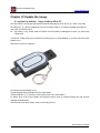
1
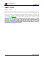
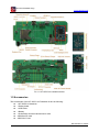
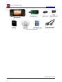
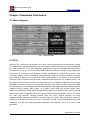
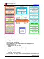
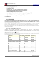
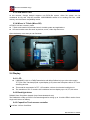
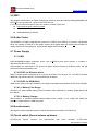
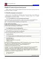
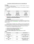
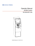
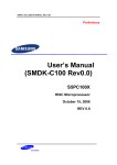
KIT-S5PC110 Use manual
Ver 1.0
Date: 07-07-2010
Boardcon Embedded design
Boardcon Embedded design
www.armdesigner.com
Rev
Date
Description
1.0
2010-07-07
The initial Released Version
For more information, please visit the web site: http:// www.armdesigner.com
Ver. 1.0 — 7/7/2010
2
Boardcon Embedded design
www.armdesigner.com
Index
KIT-S5PC110 USE MANUAL ............................................................................................................. 1
CHAPER I OVERVIEW ......................................................................................................................... 4
1.1 Introduction ............................................................................................................................ 4
1.2 Accessories ............................................................................................................................ 5
CHAPTER II HARDWARE INFORMATION................................................................................................. 7
2.1 Block diagram ........................................................................................................................ 7
2.2 CPU ....................................................................................................................................... 7
2.3 MEMORY ............................................................................................................................. 10
2.4 Display ................................................................................................................................. 11
2.5 WIFI ..................................................................................................................................... 12
2.6 Audio Codec......................................................................................................................... 12
2.7 Power Supply ....................................................................................................................... 12
2.8 Accelerometer ...................................................................................................................... 12
2.9 Touch switch (Sound volume up/down)................................................................................ 12
CHAPTER III ANDROID SYSTEM DEVELOPMENT .................................................................................. 14
3.1 Build Development environment .......................................................................................... 14
3.2 System Compiler.................................................................................................................. 16
CHAPTER IV UPDATE THE IMAGE....................................................................................................... 18
KIT-S5PC100 Use manual
Ver. 1.0 — 7/7/2010
3
Boardcon Embedded design
www.armdesigner.com
Chaper I Overview
1.1 Introduction
Boardcon KIT-S5PC110 Evaluation Board is a compact board using Samsung ARM Cortex-A8
S5PC110 microprocessor. It takes full features of this processor and supports 512MB Mobile DDR
memory. The board has exposed many other hardware interfaces including RS232 serial port,
LCD/TSP, HDMI, SD/MMC, TF-card interface, keyboard, WiFi, The board boot the system from SD
card. It is able to support Android OS and provided the sourece code for the Linux2.6.29 BSP,
Android 1.5-R3 and Android 2.1.
Boardcon KIT-S5PC110 Evaluation Kit includes the KIT-S5PC110 evaluation board and all necessary
accessories to help users start their design of multimedia applications. The board is preloaded with
Android OS in SD card. User can display the subsystem using a 3.5" TFT LCD and Touch screen.
Along with the kit, Boardcon provides user manual, schematic drawing and datasheet documents to
help customers better understand and use the kit.
KIT-S5PC110 Use manual
Ver. 1.1 — 7/7/2010
4
Boardcon Embedded design
www.armdesigner.com
Pic 1.1 KIT-S5PC110 evaluation board
1.2 Accessories
The accessories of the KIT-S5PC110 Evaluation Kit are as following:
z 1 KIT-S5PC110 boardcon
z 1 Debug board
z 1 USB cable
z 1 Battery
z 1 Schematics and the Android source code
z 2GB MicroSD card
z 2GB SDHC Card
KIT-S5PC110 Use manual
Ver. 1.1 — 7/7/2010
5
Boardcon Embedded design
www.armdesigner.com
Pic 1.2 the accessories
KIT-S5PC110 Use manual
Ver. 1.1 — 7/7/2010
6
Boardcon Embedded design
www.armdesigner.com
Chapter II Hardware information
2.1 Block diagram
Pic 2.1 Block diagram
2.2 CPU
S5PC110 is a 32-bit RISC cost-effective, low power, and high performance microprocessor solution
for mobile phones and general applications. It integrates the ARM Cortex-A8 core, which implements
the ARM architecture V7-A with supporting peripherals.To provide optimized Hardware (H/W)
performance for the 3G and 3.5G communication services, S5PC110 adopts 64-bit internal bus
architecture. This includes many powerful hardware accelerators for tasks such as motion video
processing, display control, and scaling. Integrated Multi Format Codec (MFC) supports encoding
and decoding of MPEG-1/2/4, H.263, and H.264, and decoding of VC1 and Divx. This hardware
accelerator (MFC) supports real-time video conferencing and Analog TV out, HDMI for NTSC, and
PAL mode. S5PC110 has an interface to external memory that is capable of sustaining heavy memory
bandwidths required in high-end communication services. The memory system has Flash/ ROM
external memory ports for parallel access and DRAM port to meet high bandwidths. DRAM controller
supports LPDDR1 (mobile DDR), DDR2, or LPDDR2. Flash/ ROM port supports NAND Flash,
NOR-Flash, OneNAND, SRAM, and ROM type external memory. To reduce the total system cost and
enhance the overall functionality, S5PC110 includes many hardware peripherals such as TFT 24-bit
true color LCD controller, Camera Interface, MIPI DSI, CSI-2, System Manager for power
management, ATA interface, four UARTs, 24-channel DMA, four Timers, General I/O Ports, three I2S,
S/PDIF, three IIC-BUS interface, two HS-SPI, USB Host 2.0, USB 2.0 OTG operating at high speed
(480Mbps), four SD Host and high-speed Multimedia Card Interface, and four PLLs for clock
generation.
KIT-S5PC110 Use manual
Ver. 1.1 — 7/7/2010
7
Boardcon Embedded design
www.armdesigner.com
Features:
• CortexA8 based CPU Subsystem with NEON, Samsung ARM Cortex-A8 S5PC110, up to
1GHz Operating Frequency
• 32/32KB I/D Cache, 512KB L2 Cache
• Operating System: Android2.1TM
• Memory: ROM-2GB(TFLASH), RAM-512MB(Mobile DDR 400Mega data rate)
• Storage & Expansion Slot
Standard SD/SDHC card (up to 32GB)
Standard
• Connectivity: Bluetooth 2.0+EDR, WIFI IEEE 802.11b/g
• Input and Output:
3.5mm audio jack
HDMI type-C Connector
TTA-20 (USB, Charging, Line-out/in)
• Audio: AAC,AAC+, MP3. Built-in speaker and microphone, standard 3.5mm headphone jack
KIT-S5PC110 Use manual
Ver. 1.1 — 7/7/2010
8
Boardcon Embedded design
www.armdesigner.com
• Video: MP4, H.264. Standard type-C HDTV,supports 1080p via HDMI cable (H.264 +AAC
based MP4 container format)
• Display:
3.5-Inch TFT-LCD capacitive touch
320 x 480 (HVGA) resolution
• Device Control
4way DPAD
8keys (Home, Menu, Back, Enter, A, B, X, Y)
Capacitive Touch volume
• Battery
Detachable Li-Ion battery 1300 mA
• Sensor
3-axis Accelerometer sensor
Geo magnetic field sensor
• Weight
About 160g (with battery)
• Size
About (LxWxT) 150 x 76 x 16 (mm)
• 64-bit Multi-layer bus architecture
• Advanced power management for mobile applications
• ROM for secure booting and RAM for security function
• 8-bit ITU 601/656 Camera Interface up to 8M pixel for scaled and 16M pixel for un-scaled
resolution
• Multi Format CODEC provides encoding and decoding of MPEG-4/H.263/H.264up to
30fps@HD(1080p) and decoding of MPEG-2/VC1/Divx/Xvid video up to 30ps@HD(1080p)
• JPEG codec support up to 30Mpixels/s
• 3D Graphics Acceleration with Programmable Shaderup to 10M triangles/s (Transform only)
• 2D Graphics Acceleration with BitBlitand Rotation, up to 40Mpixels/s
• 1/2/4/8 bpppalletized or 8/16/24bpp non-palletized Color-TFT support up to 2048x2048
• TV-out for NTSC and PAL mode and HDMI 1.2 interface support with PHY
• MIPI-HSI, MIPI-DSI and MIPI-CSI interface support
• 1-channel AC-97 audio codec interface, 2-ch PCM serial audio interface, and 3-channel 24-bit
I2Sinterface support (5.1ch support)
• 2-channel S/PDIF interface support for digital audio
• 2-channel I2C interface (up to 400KHz) support including 1-channel for HDMI
• 3-channel HS-SPI, up to 52Mbps
• 4-channel UART including 4Mbps port for Bluetooth 2.0 and IrDA port for SIR/MIR/FIR
• On-chip USB 2.0 OTG supporting high speed (480Mbps, on-chip transceiver)
• On-chip USB 1.1 Host supporting full speed (12Mbps, on-chip transceiver)
• Asynchronous direct Modem Interface support including 16KB DPRAM
• 3-channel SD/SDIO/HS-MMC interface support including CE-ATA
• CF version 3.0 interface support for HDD
• 24-channel DMA controller
• Support 8x8 key matrix
KIT-S5PC110 Use manual
Ver. 1.1 — 7/7/2010
9
Boardcon Embedded design
www.armdesigner.com
• 10-ch 12-bit multiplexed ADC
• 2-ch CAN interface
• Configurable GPIOs
• Real time clock, PLL, timer with PWM and watch dog timer
• SRAM/ROM/NOR/NAND Interface with x8 or x16 data bus
• MuxedOneNANDInterface with x16 data bus
• 1-port Mobile DDR Interface with x32 data bus (up to 333Mbps/pin DDR)
• 1-port DDR2 interface with x16 or x32 data bus (333Mbps/pin DDR)
• 1-port LPDDR2 interface (up to 333Mbps/pin DDR)
2.3 MEMORY
2.3.1 DDR2 512MB
Hynix DDR2 memory chips provide 512MB RAM which opens up a wide range of production and
development opportunities. DDR2 memory consumes more power than MobileDDR. But, it is pretty
much cost effective for huge memory space.
You can choose memory vendor for example Samsung/Hynix/Elpida/Micron or others due to PC
industry standard. DDR2 8Bit-bus-width memory is being used for PC/Notebook memory module.
Each chip has 8-bit data-bus-width with 128MB. We mounted 4 chips to make 32bit data bus and total
memory size is 512MB.
2.3.2 2GB T-Flash(Micro-SD) Card
Traditional memory (Like NOR-FLASH / NAND-FLASH) can't be found in KIT-S5PC110.
KIT-S5PC110 has totally different booting method. KIT-S5PC110 implements direct T-Flash booting
with excellent iROM feature of S5PC110.
KIT-S5PC110 has 2Gbyte T-flash(removable) memory card for system area. Assume it has 3,862,528
blocks(sectors) and each block has 512bytes.
Area Name
Size in bytes From(sector #) To(Sector #)
eFuse
1K
3862526
3862527
U-boot BL1
8K
3862510
3862525
U-boot Environment variables 16K
3862478
3862509
U-boot BL2
512K
3861454
3862477
4M
3854336
3862527
1GB
0
2097152
Reserved
Linux Kernel
Reserved
EXT3 for Android system
Note: Reserved area will be used for FW update and Recovery purpose.
KIT-S5PC110 Use manual
Ver. 1.1 — 7/7/2010
10
Boardcon Embedded design
www.armdesigner.com
2.3.3 2GB SDHC Card
At this moment, Google Android supports only FAT32 file system. Other file system can be
considered for big size 720p-HD contents. 2GB/4GB/8GB seems to be working well. But, 16GB
memory card has some compatibility issues.
2.3.4 Where is T-flash (Micro-SD)
KIT-S5PC110 has 2 memory cards.
z T-flash card contains boot-loader, kernel, Android system and applications.
z SD card contains user files such as pictures, music, video clips and so on.
Open the battery cover and you can find them.
2.4 Display
2.4.1 LCD
z
z
z
LMS350DF01-001 is a TMR(Transmissive with Micro Reflective) type color active matrix
TFT (Thin Film Transistor) liquid crystal display (LCD) that uses amorphous silicon TFT as a
switching devices.
This model is composed of a TFT- LCD module, a driver circuit and a back-light unit.
The resolution of a 3.5" contains 320 x 480 dots and can display up to 16,777,216 colors.
2.4.2 Back-light driver
DW8400 from DongWoon Anatech (http://www.dwanatech.com)
The DW8400 is a step-up DC/DC converter designed for driving up to 10 white LEDs in series from a
single cell Lithium-Ion battery.
2.4.3 Capacitive Touch screen controller
TouchCore 3.0 from CoreRiver.
KIT-S5PC110 Use manual
Ver. 1.1 — 7/7/2010
11
Boardcon Embedded design
www.armdesigner.com
2.5 WIFI
This elegant combination from Fujitsu Component, based on Marvell's industry leading 88W8686 and
CSR's BC4, brings both 802.11(b/g) to the KIT-S5PC110.
If you want to use this module for your own product, contact Fujitsu first.
z http://www.fcl.fujitsu.com/en/contact/
z Wireless Modules, Others
z Global Marketing 4 Division
2.6 Audio Codec
The WM8991 is a highly integrated low power hi-fi CODEC from Wolfson. A powerful 1W speaker
driver can operate in class D or AB modes. Stereo 24-bit sigma-delta ADCs and DACs provide hi-fi
quality audio record and playback, with a flexible digital audio interface.
2.7 Power Supply
2.7.1 PMIC
PMIC MAX8698C supplies important power rails of S5PC110 and other devices. It contains 3
Step-down DC/DCs and 9 LODs.
Unfortunately, the data sheet is not opened to public access because of Maxim's policy. We will
discuss this issue with Maxim soon.
2.7.2 DC/DC for Wireless device
Wifi-BT combo module consumes a lot of power and PMIC is not enough. So, KIT-S5PC110 takes
additional high efficient DC/DC converter MAX1556 of Maxim.
2.7.3 DC/DC for HDMI-5Volt
HDMI needs 5Volt power rail. FAN5602 is a charge pump based step up/down DC/DC from Fairchild.
2.7.4 Li+ Battery Fuel Gauge
KIT-S5PC110 reads reliable battery level information from dedicated Li+ battery gauge Max17040
from Maxim.
2.7.5 Li+ Battery Charger
The XC6802 is a constant-current/constant-voltage linear charger IC for single cell lithium-ion
batteries. Current source is USB-bus power.
2.8 Accelerometer
The digital 3-axial acceleration sensor of Bosch Sensortec is included in KIT-S5PC110.
2.9 Touch switch (Sound volume up/down)
KIT-S5PC110
volume
switches
are
implemented
with
touch
sensitive
IC TS01 from
KIT-S5PC110 Use manual
Ver. 1.1 — 7/7/2010
12
Boardcon Embedded design
www.armdesigner.com
AD-semiconductor.
KIT-S5PC110 Use manual
Ver. 1.1 — 7/7/2010
13
Boardcon Embedded design
www.armdesigner.com
Chapter III Android System Development
Note: Compile the Android system, please use the Ubuntu 9.04 version, the other version may
be have some problem for compiling.
3.1 Build Development environment
Users in the use KIT-S5PC110 developed; they must first build a good ARM Linux
cross-development environment. Below to ubuntu9.04 operating system as an example,
cross-development environment to build.
3.1.1 The installation of cross-compiling environment
Insert CD-ROM, ubuntu mount the CD-ROM to / media / cdrom directory, cross-compilation tool
stored in the / media /cdrom/tools directory, the name for the cross-4.2.2-eabi.tar.bz2.
Users ` the following command to install the cross compiler tools:
# sudo mkdir /usr/local/arm
# sudo tar xvjf cross-4.2.2-eabi.tar.bz2 –C /usr/local/arm
# sudo tar xvjf 4.3.1-eabi.tar.gz –C /usr/local/arm
3.1.2 Add Path in your environment file
Modify your ~/.bashrc file to add a new path with editor (gedit or vi)
PATH=$PATH:/usr/local/arm/4.2.2-eabi/usr/bin
To apply this change login again or restart the .bashrc
# source .bashrc
3.1.3 Check whether tool-chain path set up is correct or not.
# arm-linux-gcc -v
Using built-in specs.
Target: arm-unknown-linux-gnueabi
Configured with:
/home/scsuh/workplace/coffee/buildroot-20071011/toolchain_build_arm/gcc-4.2.2/config
ure --prefix=/usr --build=i386-pc-linux-gnu --host=i386-pc-linux-gnu
--target=arm-unknown-linux-gnueabi --enable-languages=c,c++
--with-sysroot=/usr/local/arm/4.2.2-eabi/
--with-build-time-tools=/usr/local/arm/4.2.2-eabi//usr/arm-unknown-linux-gnueabi/bin
--disable-__cxa_atexit --enable-target-optspace --with-gnu-ld --enable-shared
--with-gmp=/usr/local/arm/4.2.2-eabi//gmp --with-mpfr=/usr/local/arm/4.2.2-eabi//mpfr
--disable-nls --enable-threads --disable-multilib --disable-largefile --with-arch=armv4t
--with-float=soft --enable-cxx-flags=-msoft-float
Thread model: posix
gcc version 4.2.2
KIT-S5PC110 Use manual
Ver. 1.1 — 7/7/2010
14
Boardcon Embedded design
www.armdesigner.com
3.1.4 Download and Install essential packages for android
1) Android requires the following system packages:
z flex: This lexical analyzer generator is used to read a given input file for a description of a
scanner to generate.
z bison: This is a general-purpose parser generator.
z gperf: This is a perfect hash function generator.
z libesd0-dev: This enlightened sound daemon (dev files) is used to mix digitized audio
streams for playback by a single device.
z libwxgtk2.6-dev: This package provides GUI components and other facilities for many
different platforms.
z build-essential: This package contains a list of packages considered fundamental to building
Debian packages.
z Android source code includes a hard dependency on the Java Developer Kit (JDK) 5.0
Update 12 or greater.
Download packages.
# sudo apt-get install flex bison gperf libsdl-dev libesd0-dev libwxgtk2.6-dev
build-essential zip curl
# sudo apt-get install valgrind
2) Android also needs Phython 2.4 or higher. But, Ubuntu has Python 2.5 in general.
3) Install JDK 5.0 Update12 or later.
# sudo apt-get install sun-java6-jdk
4) Add Path in your environment file. Modify your ~/.bashrc file to add a new path with editor (gedit or
vi)
export PATH=/home/$USER/bin:$PATH
export JAVA_HOME=/usr/lib/jvm/java-6-sun-1.6.0.16
export ANDROID_JAVA_HOME=$JAVA_HOME
5) To apply this change login again or restart the .bashrc
# source .bashrc
Optional!! If you meet compile error due to JDK version mismatching, add this items in to Synaptic package source.
(sudo vi /etc/apt/sources.list)
deb http://archive.ubuntu.com/ubuntu/ jaunty multiverse
deb http://archive.ubuntu.com/ubuntu/ jaunty-updates multiverse
KIT-S5PC110 Use manual
Ver. 1.1 — 7/7/2010
15
Boardcon Embedded design
www.armdesigner.com
sudo apt-get update
And install old version JDK 5. and choose 1.5.0-sun in update-alternatives menu.
sudo apt-get install sun-java5-jdk
sudo update-alternatives --config java
sudo update-alternatives --config javac
Modify your ~/.bashrc file for JAVA_HOME environment variable. And, Apply it.
export JAVA_HOME=/usr/lib/jvm/java-1.5.0-sun
3.2 System Compiler
3.2.1 Ready to build file
All components of the system source code of the linux directory in the CD-ROM, the user before
carrying out the development need to untar them to the linux system, such as:
# mkdir ~/work
# cd ~/work
# tar xvzf /media/cdrom/linux/android.tar.gz
# tar xvzf /media/cdrom/linux/linux.tar.gz
# tar xvzf /media/cdrom/linux/uboot.tar.gz
After you perform these operations, the current directory will be generated android, linux, uboot 4
directory.
3.2.2 Compile the bootloader
# cd ~/work/odroids_uboot
# make mrproper
# make hkdkc110_mmc_config
# make
If there is no error, u-boot.bin should be generated and file size is about 130~150Kbyte.
3.2.3 linux kernel compilation
To start Kernel compile, .config file should be made first. You can make .config with below command.
# cd ~/work/odroids_linux
# make odroid_S_mmc_defconfig
Let's start compile !
KIT-S5PC110 Use manual
Ver. 1.1 — 7/7/2010
16
Boardcon Embedded design
www.armdesigner.com
# make zImage
If you can build kernel successfully, you will have "arch/arm/boot/zImage" (approximately 2Mbytes).
3.2.4 Compile the Android file system
To build the files, run make from within your working directory:
# cd ~/work/odroids_android
# ln -s vendor/sec/odroidt/build_android.sh
# ./build_android.sh
./odroidt_build.sh
• If there is no problem, you can see below message. rootfs directory is automatically
generated and all root file system of Android is located in that directory.(odroidt-img folder)
ok sucess !!!
#
•
Note: Compile takes about 20 minutes with latest multi-core CPU based computer. Some old
computer or virtual machine may need about 2 hours.
KIT-S5PC110 Use manual
Ver. 1.1 — 7/7/2010
17
Boardcon Embedded design
www.armdesigner.com
Chapter IV Update the image
4.1 update the android
image to Micro SD in PC
You can write the raw image files with this special utility directly from XP PC to T-flash. The utility
KIT-S5PC110_TF_Burner_098a.exe is at the CD:/tools/ folder, if you want to update the image to
micro SD, you should use it.
z This utility is very useful when KIT-S5PC110 boot-loader is damaged or when you have new
T-flash card.
1) Remove T-flash card from KIT-S5PC110 and plug it in to Card Reader. If you don't have the card
reader, buy it.
This picture is just an example.
2) Connect the card reader to PC.
3) Check which drive is assigned for the card reader.
4) Run ODROID_S_TF_Burner_21a.exe( this tools in the tools folder)
5) Select drive of the card reader and Browse button near by android Image file and choose
"odroids-20100622.odt"
This file was in the tools folder. Such as the follow picture
KIT-S5PC110 Use manual
Ver. 1.1 — 7/7/2010
18
Boardcon Embedded design
www.armdesigner.com
6) Click "START" button and writing process will be done quickly.
Note) Do not change other parameters. Changing will cause malfunction.
Where is T-flash (Micro-SD)
KIT-S5PC110 has 2 memory cards.
•
T-flash card contains boot-loader, kernel, Android system and applications.
•
SD card contains user files such as pictures, music, video clips and so on.
Open the battery cover and you can find them.
KIT-S5PC110 Use manual
Ver. 1.1 — 7/7/2010
19
Boardcon Embedded design
www.armdesigner.com
4.2 update the image to Micro SD by usb device
4.2.1 update the u-boot.bin file
Use Windows utility DNW.exe and USB driver (position: in tools folder)
1) Connect Debug board and PC serial port with Serial Cable(1:1)
2) Run serial communication software in PC (HyperTerminal/SecureCRT/etc)
3) Configure serial port options (COM port, Baudrate : 115200, DATA : 8, STOP : 1, No-Parity, No
Flow Control)
4) Turn on Odroid and you can see the below booting message. Be sure to press any key quickly to
stop the OS booting process.
OK
U-Boot 1.3.4-dirty (May 18 2010 - 23:33:57) for HKDKC110 D Type
CPU:
S5PC110@1000MHz(OK)
APLL = 1000MHz, HclkMsys = 200MHz, PclkMsys = 100MHz
MPLL = 667MHz, EPLL = 80MHz
HclkDsys = 166MHz, PclkDsys = 83MHz
HclkPsys = 133MHz, PclkPsys = 66MHz
SCLKA2M = 200MHz
Serial = CLKUART
Board:
HKDKC110
I2C:
pres(1), div(3)
ready
DRAM:
256 MB
Flash:
1 MB
SD/MMC: 1886MB
Muxed OneNAND 512MB 1.8V 16-bit (0x50)
OneNAND version = 0x013e
5) With "dnw" command, you can download any binary file to Odroid RAM from PC via USB.
HKDKC110 # run dnwu
Insert a OTG cable into the connector!
6) If you plug in the USB Cable, you are ready to send binary files to board.
Insert a OTG cable into the connector!
OTG cable Connected!
KIT-S5PC110 Use manual
Ver. 1.1 — 7/7/2010
20
Boardcon Embedded design
www.armdesigner.com
Now, Waiting for DNW to transmit data
7) It's time to execute DNW utility. But, you should install the USB driver first. Driver installation is only
required for the first time of USB connection. Driver file location should NOT be automatic selection.
The driver was in the tools folder.
8) Select the driver file and complete installation.
9) Execute the DNW utility software. Ignore serial port settings, if you are familiar with other serial
console software. Please also check for USB:OK to make sure the connection is good.
10) You can start the download with the menu for USB Port -> Download to select file to send.
11) After downloading, the uboot will be download ok..
4.2.1 update the kernel file
1) Turn on Odroid and you can see the below booting message. Be sure to press any key quickly to
stop the OS booting process.
OK
U-Boot 1.3.4-dirty (May 18 2010 - 23:33:57) for HKDKC110 D Type
CPU:
S5PC110@1000MHz(OK)
APLL = 1000MHz, HclkMsys = 200MHz, PclkMsys = 100MHz
MPLL = 667MHz, EPLL = 80MHz
HclkDsys = 166MHz, PclkDsys = 83MHz
HclkPsys = 133MHz, PclkPsys = 66MHz
SCLKA2M = 200MHz
Serial = CLKUART
Board:
HKDKC110
I2C:
pres(1), div(3)
ready
DRAM:
256 MB
Flash:
1 MB
SD/MMC: 1886MB
Muxed OneNAND 512MB 1.8V 16-bit (0x50)
OneNAND version = 0x013e
2) With "dnw" command, you can download any binary file to Odroid RAM from PC via USB.
HKDKC110 # run dnwk
Insert a OTG cable into the connector!
3) If you plug in the USB Cable, you are ready to send binary files to board.
KIT-S5PC110 Use manual
Ver. 1.1 — 7/7/2010
21
Boardcon Embedded design
www.armdesigner.com
Insert a OTG cable into the connector!
OTG cable Connected!
Now, Waiting for DNW to transmit data
4) Execute the DNW utility software. Ignore serial port settings, if you are familiar with other serial
console software. Please also check for USB:OK to make sure the connection is good.
5) You can start the download with the menu for USB Port -> Download to select file to send.
5) After downloading, the zImage will be download ok..
4.3 update the Android image to Micro SD
<Method > update the rootfs that you Compiled to Micro SD
1) Insert the T-Flash in to Card reader and connect the card reader to Linux PC.
2) Copy all files in the odroidt-img/system/ to EXT3 partition of T-Flash.
3) Normally when you plug the Card reader into Ubuntu PC, Ubuntu will mount it automatically. You
need to remember the mounting point.
4) To find the mounting points, perform below commands.
# mount
/dev/sdc1 on /media/disk-1 type ext3 (rw,nosuid,nodev,uhelper=hal) ---> Mount
T-Flash first partition(Android system): remember this!
/dev/sdc2 on /media/disk-2 type ext3 (rw,nosuid,nodev,uhelper=hal) ---> Mount
T-Flash second partition(Android data)
4.3.1 Copy rootfs to already formatted partition (Overwrite)
•
Copy root file system to EXT3 partition of T-Flash.
•
•
# sudo cp -a ~/work/odroidt-img/system/* /media/disk-1 ---> mounting point
(You may have different location)
# sync
•
Unmount the T-Flash disk and move the card from PC to KIT-S%PC110 for testing.
•
# sudo umount /media/disk-1 (or) sudo umount /dev/sdc1 ---> Unmount T-Flash first
partition(Android system)
# sudo umount /media/disk-2 (or) sudo umount /dev/sdc2 ---> Unmount T-Flash second
partition(Android data)
•
4.3.2 Copy android system to new partition (Clean & Write)
•
•
Before copying files, format the partition first. All data will be erased.
To format the T-Flash, unmount it first.
KIT-S5PC110 Use manual
Ver. 1.1 — 7/7/2010
22
Boardcon Embedded design
www.armdesigner.com
•
This is an example when device node of T-flash is /dev/sdc.
# sudo umount /dev/sdc1 ---> Unmount T-Flash first partition(Android system)
# sudo umount /dev/sdc2 ---> Unmount T-Flash second partition(Android data)
# sudo mkfs.ext3 /dev/sdc1
• If you want clean install, erase the Android data partition as below.
• WARNING! : You can delete all of data in you Host PC, if you select wrong disk/partition node
name.
# sudo mkfs.ext3 /dev/sdc2 ---> T-Flash second partition(Android data)
•
After formatting, mount the T-flash to /media/disk
# sudo mount /dev/sdc1 /media/disk ---> T-Flash first partition(Android system)
•
You can copy the android system files to T-Flash.
# sudo cp -a ~/mydroid/android/odroidt-img/system/* /media/disk ---> T-Flash first partition(Android
system)
# sync
• Unmount the T-Flash disk and move the card from PC to Odroid for testing.
# sudo umount /media/disk (or) sudo umount /dev/sdc1 ---> Unmount T-Flash second
partition(Android system)
KIT-S5PC110 Use manual
Ver. 1.1 — 7/7/2010
23