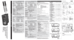
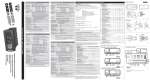
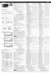
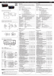
1
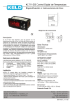
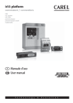
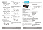
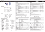
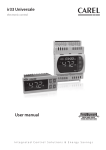
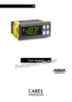
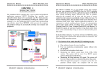
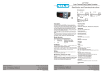
+050004122 - rel. 1.2 - 28.07.2011 EASY FREEZE (PZD*C0****): electronic controllers for low temperature ventilated refrigeration units NO POWER & SIGNAL CABLES TOGETHER READ CAREFULLY IN THE TEXT! Description PJEZ* represent a range of electronic microprocessor controllers with LED display developed for the management of refrigerating units, display cabinets and showcases. Technical specifications • • • • • • Dimensions (mm) 36 33 28.5 74 Electronic controllers for low temperature ventilated refrigeration units Power supply 115 or 230Vac Ambient probe NTC Compressor relay 16A Defrost relay 8A Evaporator fan relay 8A 71x29 81 Display and functions 10 58 65,29 3 Fig.1 Panel mounting During normal operation, the controller displays the temperature read by probe 1. In addition, the display has LEDs that indicate the activation of the control functions (see Table 1), while the 3 buttons can be used to activate/deactivate some of the functions (see Table 2). LEDs and associated functions Front (with 2 screws ø 2,5x12 mm) icon 1 Pozidriv type function on on on all compressor fan defrost alarm Do not tighten excessively start up blink request request request - ON ON ON ON Tab. 1 max 2,5 Table of functions activated by the buttons Fig.2 normal operation button Rear (with 2 quick-fit side brackets) 2 PUSH 1 normal operation OFF off off off no alarm ON 3 2 serial conv. prog. key IROPZ485S0 IROPZKEY* or PSOPZKEY* Fig. 3 pressing the button alone start up pressed together up ON/OFF more than 3 s: toggle ON/OFF Pressed together start/stop continuous cycle down defrost more than 3 s: start/stop defrost for 1 s display firmware vers. code set mute - 1 s.: display/set the setpoint - more than 3 s: access parameter setting menu (enter password ‘22’) - mute audible alarm (buzzer) for 1 s RESET current EZY set Tab. 2 Electrical connections PZD0C0P001 Setting the setpoint (desired temperature) Step Action Effect Meaning 1 Keep SET button pressed for 2 s After 1 sec currently setpoint value will It’s regulation setpoint flash on display currently active 2 Press UP or DOWN buttons Setpoint value will chang Set desired value 3 Press SET button Controller will visualize temperature read by probes again Setpoint is modified and saved 230 Vac Tab. 3 Fig. 4 NTC PROBES N 230V~ -10T50 8(4)A 10(10)A EN60730-1 8A 2FLA 12LRA 12A 10FLA 60LRA UL 873 250 Vac NTC PROBES 1 2 3 4 5 L 6 7 L N 115V~ SERIAL CONV PROG. KEY 8 9 10 11 AMB. T. PZD4C0H101 L 8 9 10 11 DEF. T. L 6 7 AMB. T. 1 2 3 4 5 PROG. KEY Ref. C614A217/R0 8A 2FLA 12LRA 12A 10FLA 60LRA UL 873 250 Vac Ref. C614A216/R0 EN60730-1 Use copper conductors only 10(10)A DI / NTC 8(4)A SERIAL CONV DI / NTC -10T50 DEF. T. PZD4C0H001 Use copper conductors only Accessing and setting the parameters Fig. 5 Step 1 Action Effect After 3 sec display will visualize “PS” Meaning 2 Keep SET button pressed for 3 s Press SET button again Password is requested Display will visualize “0” blinking 3 Press UP or DOWN button Visualized value on display will change 4 Press SET button After 5 sec the first parameter, “/5”, will be It’s the name of the first visualized on display parameter 5 Press UP or DOWN button Parameter list will be scrolled on display (refer to Table of parameters) 6 Press SET button Display will visualize value of the selected It’s the currently parameter parameter value 7 Press UP or DOWN button Parameter value visualized on display will Set desired value change 8 Press SET button Display will visualize parameter name again Attention: parameters updating is not yet active 9 Repeat steps 5, 6, 7 and 8 for all desired parameters 10 Keep SET button pressed for 5 s Controller will visualize temperature read by probes again Attention: now parameters updating will be active Insert password “22” Select desired parameter Tab. 4 Table of parameters Switching the device ON/OFF Parameter PS / /5 /6 /C1 /C2 r St rd PASSWORD PROBE PARAMETERS Select °C / °F ( 0 = °C; 1 = °F) Disable decimal point (1 disabled) Probe calibration Probe 2 calibration CONTROL PARAMETERS Control temperature Control differential (hysteresis) c c0 c1 c4 COMPRESSOR PARAMETERS Comp. and fan start delay after start-up Min. time between successive comp. starts Compressor safety (duty setting) d d0 DEFROST PARAMETERS Type of defrost (0= heater; 1= hot gas; 2= heater by time; 3= hot gas by time; 4= heater by time with temp. cont.) Interval between two defrosts End defrost temperature Max. or effective defrost duration Defrost when the instrument is switched on (1= activated) Disable temperature display during defrost (1= display disabled) Dripping time after defrost Defrost probe reading dI dt dP d4 d6 dd d/ A A0 AL AH Ad F F0 F1 F2 F3 OTHER SETTINGS Enable keypad 0= keypad disabled 1= keypad enabled 2= keypad enabled except for ON/OFF function EZY restore the Default settings UOM - 0 0 -50.0 -50.0 °C/°F °C/°F 1 1 50.0 50.0 0 0 0.0 0.0 -50.0 90.0 0.0 19.0 -18.0 °C/°F 2.0 °C/°F 0 0 0 100 100 100 0 1 15 min min min 0 4 0 - 0 50.0 1 0 0 0 - 199 130.0 199 1 1 15 - 6 8 25 0 1 1 - h/min °C/°F min/s min °C/°F -20.0 -50.0 -50.0 0 20.0 250.0 250.0 199 -2.0 -50 50 0 °C/°F °C/°F °C/°F min 0 1 1 - 50.0 0 0 130.0 2 1 1 1 1 °C/°F - 0 2 1 - 0 1 0 Tab. 5 Table of alarms Alarm code E0 E1 LO HI EE EF Ed dF buzzer and alarm relay active inactive active active inactive inactive inactive inactive LED Description Parameters involved ON ON ON ON ON ON ON OFF probe 1 error= control probe 2 error= defrost low temperature alarm high temperature alarm unit parameter error operating parameter error defrost ended by timeout defrost running [d0 = 0 / 1] [AL] [Ad] [AH] [Ad] [dP] [dt] [d4] [A8] [d6=0] Press DOWN for more than 3 s (the defrost starts only if the temperature conditions are valid). Continuous cycle Press UP and DOWN together for more than 3 s. Technical specifications 115 Vac +10 / -15% 50/60 Hz 230 Vac -10% +15% 50/60 Hz rated power inputs relay outputs 3,5 VA NTC probes 16 A relay UL: 12 A Res. 5 FLA 30 LRA - 240 Vac C300, EN60730-1: 12(2) A NO/NC, 10(4) A up to 60 °C NO, 2(2) A CO - 250 Vac 2HP ralay UL: 12 A Res. 5 FLA 60 LRA - 240 Vac, EN60730-1: 10(10) A - 250 Vac, 8 A relay UL: 8 A Res. 2 FLA 12 LRA - 240 Vac C300, EN60730-1: 8(4) A NO, 6(4) A NC, 2(2) A CO - 250 Vac type of probe Std CAREL NTC 10 K at 25 °C connections Screw terminals for cables with cross-sect. from 0.5 mm2 to 1.5 mm2 Rated maximum current per terminal 12 A assembly Terminal: using screws from the front panel or with rear brackets Interface: wall mounting, 4 screws, spacing 101x151 mm display 3 digit LED display with sign (-199 to 999) and decimal point; six status LEDs operating conditions -10T50 °C - humidity <90% rH non-condensing storage conditions -20T70 °C - humidity <90% rH non-condensing range of measurement -50T90 °C (-58T194 °F) - resolution 0.1 °C/°F front panel index of protection panel installation with IP65 type 1 gasket case plastic terminal, 81x36x65 mm classification according to protection Class II when suitably integrated against electric shock environmental pollution normal PTI of the insulating material 250 V period of stress across the insulating parts long category of resistance to heat and fire category D (UL94 - V0) immunity against voltage surges category 1 type of action and disconnection 1C relay contacts no. of relay automatic operating cycles EN60730-1: 100,000 operations UL: 30,000 operations (250 Vac) software class and structure Class A cleaning the instrument Only use neutral detergents and water. cable max. lenght serial: 1 km probes: 30 m relay: 10 m Safety standards How to restore the Default settings (refer to table of parameters in this sheet) 1) Access parameter EZY (entering password 22 and scroll parameter list). 2) Select the desired configuration: • EZY = 0 No changes; • EZY = 1 Restore of default settings (refer to Table of parameters in this sheet); 3) Exit the setting procedure (holding SET button for more than 3 sec). 4) Power off the device and then power it on again while holding SET button. 5) The display shows “CE” to indicate that the configuration has been restored. READ CAREFULLY IN THE TEXT! Manual defrost Tab. 7 Note: do not run the power cable less than 3 cm from the bottom part of the device or from the probes; for the connections only use copper wires. Tab. 6 NO POWER & SIGNAL CABLES TOGETHER Press UP for more than 3 s. The control and defrost algorithms are now disabled and the instrument displays the message “OFF” alternating with the temperature read by the set probe. power supply ALARM PARAMETERS Alarm and fan differential Low temperature alarm threshold/deviation (AL= 0; alarm disabled) High temperature alarm threshold/deviation (AH= 0; alarm disabled) Low and high temperature alarm delay FAN PARAMETERS Fan management: 0= fans on excluding specific phases; 1= fans on according to parameter F1 excluding specific phases Fans shutdown temperature Fans OFF when compressor OFF Fans status during defrost: 0= fan ON; 1= fan OFF H H2 Min. Max. Def. 0 200 22 WARNING: separate as much as possible the probe and digital input signal cables from the cables carrying inductive loads and power cables to avoid possible electromagnetic disturbance. Never run power cables (including the electrical panel wiring) and signal cables in the same conduits. compliant with the relevant European standards. Installation precautions: • the connection cables must guarantee insulation up to 90 °C; • ensure a space of at least 10 mm between the case and the nearby conductive parts; • digital and analogue input connections less than 30 m away; adopt suitable measures for separating the cables so as to ensure compliance with the immunity standards; Secure the connection cables of the outputs so as to avoid contact with very low voltage parts. IMPORTANT WARNINGS The CAREL product is a state-of-the-art device, whose operation is specified in the technical documentation supplied with the product or can be downloaded, even prior to purchase, from the website www.carel.com. The customer (manufacturer, developer or installer of the final equipment) accepts all liability and risk relating to the configuration of the product in order to reach the expected results in relation to the specific final installation and/or equipment. The failure to complete such phase, which is required/indicated in the user manual, may cause the final product to malfunction; CAREL accepts no liability in such cases. The customer must use the product only in the manner described in the documentation relating to the product. The liability of CAREL in relation to its products is specified in the CAREL general contract conditions, available on the website www. carel.com and/or by specific agreements with customers. Disposal of the product The appliance (or the product) must be disposed of separately in accordance with the local waste disposal legislation in force. CAREL reserves the right to modify the features of its products without prior notice. CAREL INDUSTRIES HQs Via dell’Industria, 11 - 35020 Brugine - Padova (Italy) Tel. (+39) 0499716611 – Fax (+39) 0499716600 – http://www.carel.com – e-mail: [email protected] +050004122 - rel. 1.2 - 28.07.2011