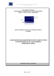
1
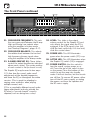
SVT-4 PRO
Bass Guitar Amplifier
Owner’s Manual
SVT-4 PRO Bass Guitar Amplifier
TABLE OF CONTENTS
Important Safety Instructions............................................................................................................ 2–3
Introduction / Features......................................................................................................................... 4
Hook-up Diagrams........................................................................................................................... 5–7
The Front Panel............................................................................................................................. 8–10
The Rear Panel............................................................................................................................ 11–13
Suggested Settings / Personal Settings........................................................................................ 14–15
Rack Mounting / Thermal Considerations............................................................................................ 16
Block Diagram................................................................................................................................... 17
Technical Specifications............................................................................................................... 18–19
Troubleshooting / Service Information................................................................................................. 19
IMPORTANT SAFETY INSTRUCTIONS
1. Read these instructions. power-supply cord or plug is damaged, liquid has
been spilled or objects have fallen into the apparatus, the apparatus has been exposed to
rain or moisture, does not operate normally, or
has been dropped.
2. Keep these instructions.
3. Heed all warnings.
4. Follow all instructions.
5. Do not use this apparatus near water.
6. Clean only with a dry cloth.
7. Do not block any ventilation openings. Install in
accordance with the manufacturer’s instructions.
8. Do not install near any heat sources such as
radiators, heat registers, stoves, or other apparatus (including amplifiers) that produce heat.
9. Do not defeat the safety purpose of the polarized or grounding-type plug. A polarized plug
has two blades with one wider than the other. A
grounding-type plug has two blades and a third
grounding prong. The wide blade or the third
prong are provided for your safety. If the provided
plug does not fit into your outlet, consult an electrician for replacement of the obsolete outlet.
10. Protect the power cord from being walked
on or pinched particularly at plugs, convenience
receptacles, and the point where they exit from
the apparatus.
11. Only use attachments/accessories specified
by the manufacturer.
12. Use only with a cart, stand,
tripod, bracket, or table specified
by the manufacturer, or sold with
the apparatus. When a cart is used,
use caution when moving the cart/
apparatus combination to avoid
injury from tip-over.
PORTABLE CART
WARNING
13. Unplug this apparatus during lightning storms
or when unused for long periods of time.
14. Refer all servicing to qualified service personnel. Servicing is required when the apparatus has been damaged in any way, such as
2
15. Do not overload wall outlets and extension
cords as this can result in a risk of fire or electric
shock.
16. This apparatus shall not be exposed to dripping or splashing, and no object filled with
liquids, such as vases or beer glasses, shall be
placed on the apparatus.
17. This apparatus has been designed with Class-I
construction and must be connected to a mains
socket outlet with a protective earthing connection
(the third grounding prong).
18. The MAINS plug or an appliance coupler is
used as the disconnect device, so the disconnect
device shall remain readily operable.
19. For the terminals marked with symbol of “ ”
may be of sufficient magnitude to constitute a risk
of electric shock. The external wiring connected to the terminals requires installation by
an instructed person or the used of ready-made
leads or cords.
CAUTION
AVIS
RISK OF ELECTRIC SHOCK. DO NOT OPEN
RISQUE DE CHOC ELECTRIQUE. NE PAS OUVRIR
CAUTION: TO REDUCE THE RISK OF ELECTRIC SHOCK DO NOT REMOVE COVER (OR BACK)
NO USER-SERVICEABLE PARTS INSIDE. REFER SERVICING TO QUALIFIED PERSONNEL
ATTENTION: POUR EVITER LES RISQUES DE CHOC ELECTRIQUE, NE PAS ENLEVER LE COUVERCLE.
AUCUN ENTRETIEN DE PIECES INTERIEURES PAR L'USAGER.
CONFIER L'ENTRETIEN AU PERSONNEL QUALIFIE.
AVIS: POUR EVITER LES RISQUES D'INCENDIE OU D'ELECTROCUTION, N'EXPOSEZ PAS CET ARTICLE
A LA PLUIE OU A L'HUMIDITE
The lightning flash with arrowhead symbol within an equilateral triangle is
intended to alert the user to the presence of uninsulated "dangerous
voltage" within the product's enclosure, that may be of sufficient magnitude
to constitute a risk of electric shock to persons.
Le symbole éclair avec point de flèche à l'intérieur d'un triangle équilatéral
est utilisé pour alerter l'utilisateur de la présence à l'intérieur du coffret de
"voltage dangereux" non isolé d'ampleur suffisante pour constituer un risque
d'éléctrocution.
The exclamation point within an equilateral triangle is intended to alert the
user of the presence of important operating and maintenance (servicing)
instructions in the literature accompanying the appliance.
Le point d'exclamation à l'intérieur d'un triangle équilatéral est employé
pour alerter les utilisateurs de la présence d'instructions importantes pour le
fonctionnement et l'entretien (service) dans le livret d'instruction
accompagnant l'appareil.
WARNING — To reduce the risk of fire or electric shock, do not
expose this apparatus to rain or moisture.
SVT-4 PRO Bass Guitar Amplifier
NOTE: This equipment has been tested and found to comply
with the limits for a Class B digital device, pursuant to part 15 of
the FCC Rules. These limits are designed to provide reasonable
protection against harmful interference in a residential installation.
This equipment generates, uses, and can radiate radio frequency
energy and, if not installed and used in accordance with the instructions, may cause harmful interference to radio communications.
However, there is no guarantee that interference will not occur in a
particular installation. If this equipment does cause harmful interference to radio or television reception, which can be determined by
turning the equipment off and on, the user is encouraged to try to
correct the interference by one or more of the following measures:
•
Reorient or relocate the receiving antenna.
•
Increase the separation between the equipment and the
receiver.
•
Connect the equipment into an outlet on a circuit different
from that to which the receiver is connected.
•
Consult the dealer or an experienced radio/TV technician for
help.
CAUTION: Changes or modifications to this device not expressly
approved by LOUD Technologies Inc. could void the user's authority
to operate the equipment under FCC rules.
This apparatus does not exceed the Class A/Class B (whichever
is applicable) limits for radio noise emissions from digital apparatus as set out in the radio interference regulations of the Canadian
Department of Communications.
CONSIGNES DE SECURITE IMPORTANTES
ATTENTION — Le présent appareil numérique n’émet pas de
bruits radioélectriques dépassant las limites applicables aux appareils numériques de class A/de class B (selon le cas) prescrites
dans le réglement sur le brouillage radioélectrique édicté par les
ministere des communications du Canada.
Exposure to extremely high noise levels may cause permanent
hearing loss. Individuals vary considerably in susceptibility to noiseinduced hearing loss, but nearly everyone will lose some hearing
if exposed to sufficiently intense noise for a period of time. The
U.S. Government’s Occupational Safety and Health Administration
(OSHA) has specified the permissible noise level exposures shown
in the following chart.
According to OSHA, any exposure in excess of these permissible limits could result in some hearing loss. To ensure against
potentially dangerous exposure to high sound pressure levels, it is
recommended that all persons exposed to equipment capable of
producing high sound pressure levels use hearing protectors while
the equipment is in operation. Ear plugs or protectors in the ear
canals or over the ears must be worn when operating the equipment in order to prevent permanent hearing loss if exposure is in
excess of the limits set forth here:
Duration, per
day in hours
8
6
4
3
2
1.5
1
Sound
Level dBA, Slow
Response
90
92
95
97
100
102
105
0.5
0.25 or less
110
115
Typical Example
Duo in small club
Subway Train
Very loud classical music
The boss screaming at his minions about
manual deadlines
Loudest parts at a rock concert
- LIRE, SUIVRE TOUTES LES INSTRUCTIONS ET LES PRECAUTIONS D’UTILISATION
- NE PAS UTILISER PROCHE D’UNE SOURCE DE CHALEUR ET NE PAS BLOQUER OU OBSTRUER LE SYSTEME DE VENTILATION SUR CET APPAREIL. POUR UNE
UTILISATION CONFORME, CET APPAREIL NECESSITE ENVIRON 7CM D’ESPACE BIEN VENTILE AUTOUR DE SON SYSTEME DE REFROIDISSEMENT, AINSI QU’UN COURANT
D’AIR FRAIS CONSTANT
- NE PAS UTILISER CET APPAREIL PROCHE D’UNE SOURCE LIQUIDE
- NETTOYER SEULEMENT A L’AIDE D’UN CHIFFON DOUX ET SEC ET NE PAS UTILISER DE PRODUITS MENAGERS
- CONNECTER UNIQUEMENT LE CABLE D’ALIMENTATION FOURNI SUR UNE PRISE AVEC MISE A LA TERRE, ET COMPATIBLE AVEC LA TENSION, L’INTENSITE ET LA
FREQUENCE REQUISES INDIQUEES SUR LA FACE ARRIERE DE L’APPAREIL
- S’ASSURER DE NE PAS MARCHER, PLIER OU TIRER SUR LE CABLE D’ALIMENTATION
- DEBRANCHER L’APPAREIL LORS D’UNE TEMPETE OU LORS D’UNE TRES LONGUE PERIODE DE NON UTILISATION
- UTILISER UNIQUEMENT DES ACCESSOIRES SPECIFIES PAR LE FABRICANT POUR UNE UTILISATION EN TOUTE SECURITE ET POUR EVITER DES BLESSURES
- ATTENTION: AFIN DE PREVENIR TOUT RISQUE DE CHOCS ELECTRIQUES OU DE DEBUT D’INCENDIE, NE PAS EXPOSER CET APPAREIL A LA PLUIE ET A L’HUMIDITE
- TOUT ENTRETIEN DOIT ETRE FAIT PAR UN TECHNICIEN QUALIFIE
- NOS AMPLIFICATEURS PEUVENT PRODUIRE DE TRES HAUTES PRESSIONS ACOUSTIQUES QUI PEUVENT CAUSER DES DOMMAGES AUDITIFS PERMANENTS OU
DEFINITIFS. L’UTILISER AVEC UNE GRANDE PRECAUTION EST CONSEILLE ET DES PROTECTIONS AUDITIVES SONT RECOMMANDEES POUR UNE UTILISATION A FORT
VOLUME.
- ATTENTION: CET APPAREIL REQUIERT UNE PRISE MURALE AVEC MISE A LA TERRE, AUX NORMES ACTUELLES ET COMPATIBLE AVEC LES SPECIFICATIONS
ELECTRIQUES SE TROUVANT EN FACE ARRIERE DE L’APPAREIL. LA PRISE ELECTRIQUE DOIT RESTER ACCESSIBLE POUR DEBRANCHER L’APPAREIL EN CAS DE DEFAUT
PENDANT L’UTILISATION
- CET APPAREIL DOIT ETRE DEBRANCHE SI IL N’EST PAS UTILISE
Elimination correcte du produit : Ce symbole indique que ce produit ne doit pas être éliminé avec les ordures ménagères, comme le prévoiT la directive WEEE (2002/96/
EC) et votre loi nationale.
Ce produit doit être remis à un site de recyclage des déchets électriques et des équipements électroniques (EEE).
Un mauvais recyclage de ce type de déchet peut avoir de possibles impacts négatifs sur l’environnement et la santé humaine dus aux émanations de substances.
Dans un même temps, votre coopération à un recyclage correct de ce produit contribuera à la bonne utilisation des ressources naturelles.
Pour connaître l’endroit où il est possible de recycler ces équipements, merci de contacter votre mairie, les services de recyclages ou le service des déchets ménagers.
Correct disposal of this product: This symbol indicates that this product should not be disposed of with your household waste,
according to the WEEE directive (2012/19/EU) and your national law. This product should be handed over to an authorized
collection site for recycling waste electrical and electronic equipment (EEE). Improper handling of this type of waste could have
a possible negative impact on the environment and human health due to potentially hazardous substances that are generally
associated with EEE. At the same time, your cooperation in the correct disposal of this product will contribute to the effective
usage of natural resources. For more information about where you can drop off your waste equipment for recycling, please
contact your local city office, waste authority, or your household waste disposal service.
3
SVT-4 PRO Bass Guitar Amplifier
Introduction
Congratulations! You are now the proud owner of an Ampeg SVT-4 PRO bass guitar amplifier. This versatile and powerful bass amplifier delivers up to 1600 watts of unsurpassed quality, offering the classic vibrance of tubes, as well as contemporary features.
The SVT-4 PRO amplifier is an ideal companion to the Classic Series, Pro Series,
or PF cabinets, available separately.
Like all Ampeg products, your SVT-4 PRO amplifier is designed by musicians and built
using only the best of components. Each amplifier is tested to confirm that it meets our
specifications, and we believe that this amplifier is the absolute best that it can be. In order
to get the most out of your new amplifier, please read this manual before you begin playing.
Best of luck in all of your musical endeavors!
Sincerely,
The dedicated team at Ampeg
Features
• DUAL SEPARATE POWER AMPLIFIERS: Operate in true stereo or mono bridged mode
for even greater output power [pages 5–6, 12].
• BI-AMP CAPABLE: Adjustable crossover frequency control and low-to-high frequency balance control allow you to fine-tune the bi-amp abilities of the amplifier [pages 6–7, 10].
• 5-POSITION MIDRANGE SELECTOR: Take your pick from the five center frequency
points available to get just the right midrange voicing [page 9].
• COMPRESSION CONTROL: Allows you to control the dynamics of the tonal response
characteristics from the power amp, from punch to compressed [page 8].
• 9–BAND GRAPHIC EQ: Use as a “second channel” for bass solos, or to shape the
sound to your own exacting standards. An independent level control allows you to adjust
the Graphic EQ volume [page 10].
• TUNER OUT JACKS: Two jacks – one on the front panel, one on the rear panel – allows
connection to an electronic tuner and provides an “always live” monitor feed, even when
the output is muted [pages 8, 13].
• SPEAKON JACKS: For more reliable connections at higher outputs and for mono
bridged connections (in addition to 1/4" speaker out jacks) [page 11].
• TRANSFORMER BALANCED LINE OUTPUTS: Independent level control. Two transformer balanced XLR and two balanced/unbalanced 1/4" output jacks – switchable stereo
or mono (one “wet”, one “dry” signal), pre– or post–EQ [page 12].
• STEREO EFFECTS LOOP: Connect effects here for increased intensity and quieter
operation [page 13].
• POWER AMP IN AND PREAMP OUT: Two separate loops, one for each channel: a separate preamp may be connected to the Power Amp In jack and the Preamp Out jack may be connected to a slave amp [page 12].
• FOOTSWITCH CONTROL: Use a footswitch to bypass/activate the Effects Loop and to
activate the Graphic EQ and the Mute feature [page 12].
• CIRCUIT BREAKER PROTECTION: A heavy duty resettable circuit breaker provides protection against fault conditions [page 11].
4
SVT-4 PRO Bass Guitar Amplifier
Hook-up Diagrams
Full
Range
Cabinet(s)
SVT-4 PRO
MONO
BRIDGE
Mono
1
Bridged
IN
(MONO)
TO
INPUT
JACK
In this example, the SVT-4 PRO’s two internal power amplifiers are bridged together to produce maximum output power. Engage the Stereo/Mono Bridge switch [Mono Bridge
position]. Connect a heavy duty speaker cable terminated with a Speakon connector [pin 1+ = “+”, pin 1– = “–”] from the SVT-4 PRO’s Mono Bridge Output jack to the input jack
of a speaker cabinet capable of handling the extremely high output power.
Note: Be absolutely certain that the cabinet(s) are able to handle the extremely high output
power of the amp in this mode.
SVT-4 PRO
PWR
AMP B
PWR
AMP A
2
1
Full
Range
Cabinets
Dual
Mono
OUT
(STEREO)
TO
INPUT
JACK
TO
INPUT
JACK
In this example, the SVT-4 PRO’s two internal power amplifiers will each power a set of
full range cabinets. Disengage the Stereo/Mono Bridge switch [Stereo position]. Connect a
speaker cable from the SVT-4 PRO’s Power Amp A Speaker Output jack to the input jack(s) of a set of full range speakers. Next, connect a speaker cable from the SVT-4 PRO’s Power
Amp B Speaker Output jack to the input jack(s) of another set of full range speakers.
5
SVT-4 PRO Bass Guitar Amplifier
Hook-up Diagrams continued
Stereo
Stereo Effects Procesor
LEFT
OUT
2
RIGHT
OUT
INPUT
3
PWR
AMP B
Stage
Right
Cabinet(s)
EFX RET EFX RET EFX
LEFT/B RIGHT/A SEND
PWR
AMP A
5
TO
INPUT
JACK
1
SVT-4 PRO
Stage
Left
Cabinet(s)
4
OUT
TO
INPUT
JACK
(STEREO)
In this example, the SVT-4 PRO’s two internal power amplifiers will each power a set of
full range cabinets in stereo. Disengage the Stereo/Mono Bridge switch [Stereo position].
Connect a shielded cable from the Effects Send of the SVT-4 PRO to the input of a stereo
effects processor. Next, connect a shielded cable from the left output of the processor to
the SVT-4 PRO’s Effects Return Left / B jack. Connect a shielded cable from the right output
of the processor to the SVT-4 PRO’s Effects Return Right / A jack. Now connect a speaker
cable from the SVT-4 PRO’s Power Amp A Speaker Output jack to the input jack(s) of the stage
left speakers. Finally, connect a speaker cable from the SVT-4 PRO’s Power Amp B Speaker
Output jack to the input jack(s) of the stage right speakers.
Note: For Speakon connectors pin 1+ = “+”, pin 1– = “–”.
Full
Range
Cabinets
BIAMP
LO OUT
SVT-4 PRO
1
Bi-amp: Full
Range / Lows
POWER
AMP A
P.A. IN
PWR PWR
AMP B AMP A
3
2
OUT
(STEREO)
TO
INPUT
JACK
TO
INPUT
JACK
In this example, the SVT-4 PRO’s two internal power amplifiers will power both a full
range cabinet and a low frequency cabinet. The crossover point for the low frequency cabinet
is determined by the Crossover Frequency control [21]. Disengage the Stereo/Mono Bridge
switch [Stereo position]. Connect a shielded cable from the SVT-4 PRO’s Bi-amp Low Out jack
to its Power Amp A Power Amp In jack. Next, connect a speaker cable from the SVT-4 PRO’s
Power Amp A Speaker Output jack to the input jack of the low frequency cabinet(s). Finally,
connect a speaker cable from the SVT-4 PRO’s Power Amp B Speaker Output jack to the input
jack of the full range cabinet(s).
6
SVT-4 PRO Bass Guitar Amplifier
Hook-up Diagrams continued
BIAMP
HI OUT
SVT-4 PRO
BIAMP
LO OUT
1
Full
Range
Cabinet(s)
2
Bi-amp:
POWER
AMP B
P.A. IN
PWR PWR
AMP B AMP A
Highs / Lows
4
3
POWER
AMP A
P.A. IN
OUT
(STEREO)
TO
INPUT
JACK
TO
INPUT
JACK
In this example, the SVT-4 PRO’s two internal power amplifiers will power both a high
frequency cabinet and a low frequency cabinet. The crossover point for the cabinets is determined by the Crossover Frequency control [21]. Disengage the Stereo/Mono Bridge
switch [Stereo position]. Connect a shielded cable from the SVT-4 PRO’s Bi-amp High Output
jack to its Power Amp B Power Amp In jack. Connect a shielded cable from the SVT-4 PRO’s
Bi-amp Low Output jack to its Power Amp A Power Amp In jack. Next, connect a speaker
cable from the SVT-4 PRO’s Power Amp A Speaker Output jack to the input jack of the low
frequency cabinet(s). Finally, connect a speaker cable from the SVT-4 PRO’s Power Amp B
Speaker Output jack to the input jack of the high frequency cabinet(s).
SVT-4 PRO
BIAMP
HI OUT
1
BIAMP
LO OUT
2
MONO BRIDGE
Bi-amp with a
4
Second Amp
Full
Range
Cabinet(s)
POWER
AMP A
P.A. IN
(MONO
BRIDGE)
IN
(MONO)
MONO
BRIDGE
MODEL: SVP-1500
SERIAL: SVP15OOU12B
LINE: 120 V ~ 60
Hz
WATTS: 1500 MAX
3
TO
INPUT
JACK
CH A
INPUT
IN
(MONO)
TO
INPUT
JACK
In this example, the SVT-4 PRO’s two internal power amplifiers are bridged together and
will power the low frequency cabinet(s). A second amplifier will be used to power the high
frequency cabinet(s). The crossover point for the cabinets is determined by the Crossover
Frequency control [21]. Engage the Stereo/Mono Bridge switch [Mono Bridge position].
Connect a shielded cable from the SVT-4 PRO’s Bi-amp High Output jack to the input jack of
the High Frequency power amplifier. Connect a shielded cable from the SVT-4 PRO’s Bi-amp
Low Output jack to its Power Amp A Mono Bridge Input jack. Next, connect the high
frequency power amp’s Speaker Output jack to the input jack(s) of the high frequency
cabinet(s). [Observe the amplifier’s minimum load rating]. Finally, connect a heavy duty speaker cable terminated with a Speakon connector [pin 1+ = “+”, pin 1– = “–”] from the
SVT-4 PRO’s Mono Bridge Output jack to the input jack of the low frequency speaker cabinet.
7
SVT-4 PRO Bass Guitar Amplifier
The Front Panel
24 25 26
23
1
2
3
4
5
6
7
8
9
10
11
1.INPUT: The signal output from an instrument (active or passive) may be
connected to this 1/4" input by means
of a shielded instrument cable.
2. TUNER OUT: This jack supplies the only
live output when the mute switch [3] is
engaged. This allows for silent tuning
through an electronic tuner or killing the
house send with a monitor mixer send
still active. In addition, this jack may also be used as a –6 dB input (when not connected to a tuner).
3.MUTE: Press this switch in to mute all outputs except the tuner outs [2, 49].
The footswitch may also control muting if the mute switch [3] on the front
panel is left in the “out” position. (The
front panel switch is still active with the
footswitch connected. This is excellent
for tuning your bass with an electric
tuner without having to adjust any levels
to turn down the sound). The peak LED
[6] will illuminate when this switch is
engaged.
4. –15 dB: Press this switch in to reduce
the input signal by 15 dB and compensate for higher output sources.
This attenuation is suited for use with
basses that have active electronics or
high-output pickups. Use this pad if you
notice that the peak LED [6] comes on
regularly. It will reduce the chance of
overdriving the preamplifier stage and
allow more usable range and fine 8 adjustment of the gain control.
12
13
14
15
27
16
17
18
19 20
21
22
5.GAIN: This varies the amount of signal
driving the preamplifier. If a small clockwise rotation from minimum leads
to overloading and the peak LED [6]
illuminating, try engaging the –15 dB
pad [4]. This will give more usable range
with the gain control.
6. PEAK LED: This red warning LED will
come on if the input signal is too high,
the gain control [5] is set too high, or
there is too much boost from the bass
[10], midrange [11] and treble [13] controls. If it comes on regularly, even
when these controls are low, try engaging the –15 dB pad [4].
7.COMPRESSION: This controls the
amount of signal compression. At the
fully counterclockwise position there is
no compression; at the fully clockwise
position the compression ratio is 10:1.
The sonic effect of compression is
reduced dynamics, increased sustain
and a more consistent output level
regardless of how light or hard the
strings are played. The compressor is
very transparent – that is, there is very
little effect on the tone of your instrument.
8. ULTRA HI: This switch, when engaged,
enhances the amount of high frequency
output by 6 dB at 5 kHz.
9. ULTRA LO: This switch, when engaged,
enhances the amount of low-end output
by 2 dB at 40 Hz and –10 dB cut at 500 Hz.
SVT-4 PRO Bass Guitar Amplifier
The Front Panel continued
24 25 26
23
1
2
3
4
5
6
7
8
9
10
11
10.BASS: Use this to adjust the low frequency level of the amplifier. This provides up to 12 dB of boost,
or 12 dB of cut at 50 Hz. The low
frequency output is flat at the center
position.
11.MIDRANGE: Use this to adjust the midrange frequency level of the amplifier. This provides up to 15 dB of
boost, or 15 dB of cut at the center frequency selected by the frequency
control [12]. The midrange frequency
output is flat at the center position.
Rotate the control counter clockwise
for a “contoured” sound (more distant,
less midrange output) or clockwise for a
sound which really cuts through.
12.FREQUENCY: This control allows you to
select the center frequency for the midrange control [11], giving you a
choice of five “voices” for the midrange.
The numbers correspond to the following center frequencies: 1=220 Hz, 2=450 Hz, 3=800 Hz, 4=1.6 kHz, 5=3 kHz.
13.TREBLE: Use this to adjust the high frequency level of the amplifier. This
provides up to 14 dB of boost, or 19 dB of cut at 5 kHz. The high frequency output is flat at the center
position.
14.BRIGHT: When this switch is engaged, a
more lively top end response [+6 dB at
2 kHz] is added to the input signal.
12
13
14
15
27
16
17
18
19 20
21
22
15. GRAPHIC EQ: When this switch is
engaged, the 9-band graphic EQ is
enabled. A footswitch overrides this
switch.
16. LINE OUT LEVEL: This controls the
strength of the signal at the line out
jacks [40, 41, 44, 45].
17. EFFECTS BYPASS: When this switch is
engaged, the effects loop is bypassed.
A footswitch overrides this switch.
18. LIMIT DEFEAT: The SVT-4 PRO employs
internal limiter circuits to help keep
the power amplifier’s output clean at
extreme volume levels. (All amplifier’s
may begin to clip their output signals as
they approach maximum output levels,
resulting in potentially speaker-damaging
distortion.) These circuits may be
defeated by engaging this switch, which
may result in an increase in output
power but with the possibility of distortion. Use discretion whenever playing with the limit circuits defeated.
19.MASTER: Use this to control the overall output level. Use it wisely and
turn it down when making connections
or trying something new.
20. LIMIT LED: This LED will flash any time
the internal limit circuit is called upon to
keep the amplifier’s output signal clean.
This indicates that the amplifier is nearing full output and the limiter is
keeping it from clipping the output signal.
9
SVT-4 PRO Bass Guitar Amplifier
The Front Panel continued
24 25 26
23
1
2
3
4
5
6
7
8
9
10
11
21. CROSSOVER FREQUENCY: This sets
the crossover point between the Bi-amp
High and Bi-amp Low outputs when using the amplifier in bi-amp mode (see ‘Hook-up Diagrams’, pages 5–7).
22. CROSSOVER BALANCE: This adjusts
the relative level between the low and
high frequency bi-amp signals when
using the amplifier in the bi-amp mode.
23. 9–BAND GRAPHIC EQ: These sliders
control the output frequencies indicated
above each control. The center position
of each control is flat [no boost or cut].
The Graphic EQ may be used in two ways: 1) To fine tune the sound, make small adjustments at the desired frequencies and leave the EQ on throughout the entire session. (This is great for adapting to varying room acoustics when playing multiple venues) and...
2) For a completely different sound, make
larger adjustments and only activate the EQ when a “second channel” sound is
required (such as during bass solos).
10
12
13
14
15
27
16
17
18
19 20
21
22
24.LEVEL: This slider is the output volume control for the Graphic EQ and
only affects the signal when the EQ is
engaged. If the EQ’d signal is too soft,
slide the level control up; if it’s too loud,
slide this control down.
25. POWER LED: This LED illuminates
green when the power switch [27] is up.
26. ACTIVE LED: This LED illuminates when
the Graphic EQ switch [15] is engaged.
27. POWER SWITCH: Use this switch to
turn the overall system power on or
off. Press the top of the switch to turn
on the power. Press the bottom of this
switch to put the amp into standby
mode. It will not function, but the circuits
are still live. To remove AC power, either
turn off the AC mains supply, or unplug
the power cord from the speaker and
the AC mains supply.
SVT-4 PRO Bass Guitar Amplifier
The Rear Panel
38
1+ HOT, 1–
40 41
39
1+ HOT,1– RETURN
42 43
44
29
31
30
28. CIRCUIT BREAKER: The SVT-4 PRO
employs an AC line circuit breaker to
help protect against damages due to
excessive current demands. If the amplifier stops working, check the circuit breaker.
NOTE: When the circuit breaker opens, the
button will be protruding and showing a
contrasting color. You may reset the circuit
breaker by pushing it in until it latches. The
breaker must cool down for a short time
before the button will latch. If the circuit
breaker opens repeatedly with no signal
input, have the amplifier checked by a qualified service person.
29. IEC POWER INPUT CONNECTOR: This is where you connect the supplied
AC power cord.
MONO BRIDGE: 1200W rms @ 8 ohms, 1600W rms @ 4 ohms
This single Speakon® output is for utilizing the full power output potential of
the amplifier [power amp A summed with
power amp B] for a single mono send.
Stereo / Mono operation is described on
the next page [31].
47
48
32
35
36
37
BIAMP LOW/
MONO BRIDGE INPUT
33
34
POWER AMP A: 350W rms @ 8 ohms, 625W rms @ 4 ohms, 925W rms @ 2 ohms
POWER AMP B: 350W rms @ 8 ohms, 625W rms @ 4 ohms, 925W rms @ 2 ohms
Each power amp is capable of achieving
the power output ratings listed above
per side individually; you may use either
side individually or both simultaneously.
Both power amp A and power amp B
provide the choice of utilizing dual 1/4" TS outputs or a single Speakon
output per side [1+, 1–].
When using the 1/4" TS outputs, use
only speaker cables with 1/4" TS ends
to make the connections. Do not use
instrument cables as they may overheat.
We recommend using the Speakon jacks
whenever playing at full output levels.
Make sure the total speaker impedance
load is 2 ohms or greater.
For example, you could connect:
Two 16 ohm speakers (an 8 ohm load),
Two 8 ohm speakers (a 4 ohm load)
or one 2 ohm speaker.
DO NOT DEFEAT THE GROUND PRONG
OF THE AC PLUG!
30. SPEAKER OUTPUTS:
46
1+ HOT, 1–
BIAMP HIGH
INPUT
28
45
(Speakon® is a registered trademark of Neutrik AG.)
11
SVT-4 PRO Bass Guitar Amplifier
The Rear Panel continued
38
1+ HOT, 1–
39
1+ HOT,1– RETURN
40 41
42 43
44
29
30
31. STEREO / MONO BRIDGE SWITCH:
This switch sets the operating mode of
the amplifier. In the “out” position, the
amplifier is in Stereo Mode; with the
switch in the “in” position, the amplifier
is in Mono Bridged Mode.
32, 34. POWER AMP IN: These jacks connect directly to the internal power
amp for use with external preamps.
When using external sources, connect
the OUTPUT of the sources to these
jacks using shielded instrument cables
to feed the signals into the power amp sections. The internal signal is disconnected when a plug is inserted.
In the Mono Mode, Channel A = Input. In the Bi-amp Mode, Channel A = Low
(frequency) Input, Channel B = High (frequency) Input.
33, 35. PREAMP OUT: These jacks are
direct post master preamp outputs for
use with external power amps, mixers,
external effects, etc. Connect the external amp’s input to these jacks using a shielded instrument cable.
36. EFFECTS BYPASS FOOTSWITCH:
Connect a single button footswitch
to this jack for remote control of the
Effects Loops. The footswitch overrides
the front panel Effects Bypass switch.
NOTE: A footswitch may be purchased at
your local Ampeg Dealer or ordered directly
12
46
47
48
35
36
37
1+ HOT, 1–
BIAMP HIGH
INPUT
28
45
31
32
BIAMP LOW/
MONO BRIDGE INPUT
33
34
from LOUD Technologies Inc. Be sure to ask
for model #AFP1.
37. GRAPHIC EQ / MUTE
FOOTSWITCH: Connect a dual footswitch to this jack for remote Mute
and EQ On/Off control. On the stereo
1/4" plug, the tip controls Mute and the ring controls EQ On/Off. The EQ footswitch overrides the front panel
switch and the Mute function is available from either location.
NOTE: A footswitch may be purchased at
your local Ampeg Dealer or ordered directly
from LOUD Technologies Inc. Be sure to ask
for model #AFP2.
...or order model #AFP3 which may be used
for FX, EQ and Mute!
38. BI-AMP HIGH / LOW OUTPUTS: When
used in the bi-amp mode, the Bi-amp
High Out jack connects to the high frequency power amplifier and the
Bi-amp Low Out jack connects to the low
frequency power amp. [See pages 5–7].
39, 40, 43, 44. TRANSFORMER
BALANCED LINE OUTPUTS: These
jacks supply a balanced signal for connecting to a house mixing board,
recording console or external amplifiers.
The signal level at these jacks is controlled by the front panel Line Out
Level control [16] and is governed by
the Stereo / Mono switch [41] and the
Pre / Post switch [42].
SVT-4 PRO Bass Guitar Amplifier
The Rear Panel continued
38
1+ HOT, 1–
39
1+ HOT,1– RETURN
40 41
42 43
44
29
30
41. LINE OUT STEREO / MONO SWITCH:
This switch is active only when the Pre/Post switch [43] is in the “post”
position [engaged]. When active, this
switch governs the signals at the Line
Out jacks as follows:
Stereo Mode [switch out]:
• The Channel A line out jacks [43, 44] supply a signal from the Effects
Loop Return Right/A jack [46].
• The Channel B line out jacks [39, 40] supply a signal from the Effects
Loop Return Left/B jack [45].
Mono Mode [switch in]:
• The Channel A line out jacks [43, 44] supply a “wet” mono preamp signal – any external effects are applied to this signal. The Effects Loop
Left and Right returns [45, 46] are summed together, creating a mono effects signal.
• The Channel B line out jacks [39, 40] supply a “dry” mono preamp signal – no external effects are applied to this signal.
42. POST-EQ / PRE-EQ: The signal at the line out jacks can be set to either Pre-EQ or Post-EQ with this switch. With the switch in the OUT position, the signal at the jacks is Pre-EQ. This is a direct output not affected by any EQ or boost settings. With the switch
in the IN position, the signal is 46
47
48
35
36
37
1+ HOT, 1–
BIAMP HIGH
INPUT
28
45
31
32
BIAMP LOW/
MONO BRIDGE INPUT
33
34
Post-EQ and is controlled and modified by the tone controls, Graphic EQ, the Master level control, the
effects loop and the Line Out Stereo /
Mono switch.
45. EFFECTS LOOP RETURN LEFT / B:
When using stereo effects, connect the
effect’s left channel output into this jack.
Do not use this jack with mono effects.
46. EFFECTS LOOP RETURN RIGHT / A
(MONO): When using stereo effects,
connect the effect’s right channel output
into this jack. When using mono effects,
connect the effect’s output into this jack.
47. EFFECTS LOOP SEND: When using an external signal processor, connect the INPUT of the effect to this jack using a shielded instrument cable to
send the post-EQ signal to the effect for processing. The effects loop may be
bypassed by the front panel switch or by
the use of a footswitch.
48. TUNER OUT: This jack is provided for
connection to an electronic tuner and is
always live, even when the Mute switch
[3] is engaged. This allows for silent
tuning, as well as a monitor feed which
stays hot, even when the house mix is
muted.
OTHER: Make sure that the ventilation openings are not obscured in any way. This
will allow the flow of cooling air to the power
amplifier’s heatsinks.
13
SVT-4 PRO Bass Guitar Amplifier
Suggested Settings
Since so many variables
affect the actual sound of any system, the following
settings are offered as starting points to help you
find the exact sounds your
playing demands. When
using the SVT-4 PRO,
please keep in mind the following points:
• The Gain control
should be adjusted until the peak LED flashes on
strong signals. [This level
will vary depending on the
instrument and playing
style].
• The Compressor
control may be adjusted
to control the dynamic
response of the instrument.
Adjust it according to your
preference.
• The Graphic EQ may
be used to further fine-tune
these basic suggested
settings, to extend the frequency response of the
cabinet being used, to compensate for room acoustics, or to act as a
“second channel”.
Setting 1 – Classic Ampeg
OUT
OUT
OUT
OUT
Setting 2 – Funky Thing
IN
OUT
IN
OUT
Setting 3 – Ethereal Fretless
OUT
OUT
OUT
OUT
Setting 4 – “Jaco”
OUT
IN
OUT
OUT
Setting 5 – R&B Groove
OUT
OUT
OUT
OUT
Setting 6 – Downright Upright Done Right
14
OUT
OUT
OUT
OUT
SVT-4 PRO Bass Guitar Amplifier
Personal Settings
A note about the Graphic EQ:
The Graphic EQ may be used in two ways: 1) To fine tune the sound, make small adjustments at the desired frequencies and leave the
EQ on throughout the entire session. (This is great for adapting to varying room acoustics
when playing multiple venues) and...
2) For a completely different sound, make larger adjustments and only activate the EQ when a
“second channel” sound is required (such as during bass solos).
15
SVT-4 PRO Bass Guitar Amplifier
Rack Mounting
When mounting the SVT-4 PRO into a rack, the four bottom feet should be removed to maintain the three rack space height of the amplifier. Be sure to keep the feet and their
attachment bolts for future use. If the feet are reinstalled, never use screws which will protrude farther into the amplifier than the original hardware.
The rack must be a high quality enclosure capable of securely supporting the weight of the amplifier. Tighten the mounting screws securely through the amplifier’s face plate, into the rack rails. Check the rack and mounting screws occasionally to ensure a continually
safe and secure installation.
Thermal Considerations
The amplifier is fan cooled with one large fan. Air is drawn through the rear panel vent to cool down the amplifier heatsinks, and then expelled through the side panel vents.
When installing, be sure to allow sufficient air space around the front, sides and rear of the
amplifier for adequate cooling for the heatsinks. Leave at least one rack space above and
below, and at least six inches behind and in front of the chassis to allow proper ventilation.
The rear of the rack should be unobstructed and placed no closer than 10" from walls or other large obstructions. When the amplifier is first turned on, the fan runs at a low speed.
As the power output increases and the amp warms up, the fan gradually increases in speed
to provide additional cooling. If the amplifier should overheat, a thermal switch turns off the
power amplifier, allowing the heatsink to cool down. Once the amplifier has cooled to a safe operating temperature, the thermal switch resets and reactivates the amplifier. If this should occur, identify the cause of the problem and take corrective action. For example:
• Provide better ventilation
• Install a fan in the rack to move more air
• Make sure the amplifier is not overloaded with too low of a load impedance or by a short circuit on the speaker line
16
MASTER
VOLUME
(A/
MONO)
(B)
BYPASS
BYPASS
MUTE
MONO
STEREO
MONO
Σ
STEREO
LINE
OUT
LEVEL
FOOTSWITCH
-15dB PAD
FOOTSWITCH
EFFECTS
BYPASS
LINE OUT
STEREO/
MONO
INPUT
FRONT
TUNER
OUT
POST
PRE
COMPRESSION
EFFECTS
RETURN
(RIGHT/A/MONO)
EFFECTS
RETURN
(LEFT/B)
GAIN
BAL
LINE
OUT
(A/MONO)
BAL/UNBAL
LINE OUT
(A/MONO)
BAL
LINE
OUT
(B)
BAL/UNBAL
LINE OUT
(B)
PEAK
LED
COMPRESSION
EFFECTS
SEND
(MONO)
LINE OUT
PRE/POST
POST
PRE
TUBE
GAIN
STAGE
REAR
TUNER
OUT
BASS
ULTRA
HIGH
FREQ
STEREO
BRIDGE MONO
STEREO
BRIDGE MONO
BAL
BI-AMP
FREQUENCY
MIDRANGE
TREBLE
ULTRA
LOW
TONE CIRCUITS
BRIGHT
STEREO/
BRIDGED
LOW
OUT
HIGH
OUT
(X9)
9 BAND
GRAPHIC
EQ
LIMIT
DEFEAT
LIMITER
LIMIT
LED
LIMITER
LEVEL
EQ IN
POWER
AMP B
POWER
AMP A
FOOTSWITCH
PREAMP
OUT
(B)
POWER
AMP IN
(B)
SPKR
OUT
(B)
SPKR
OUT
(B)
PREAMP
OUT
(A/MONO)
POWER
AMP IN
(A/MONO)
SPKR
OUT
(A)
SPKR
OUT
(A)
1-
1-
1+
2+
1+
2+
2- SPEAKON
JACK
(B)
1+
22+
SPEAKON
JACK
(MONO
BRDG)
1-
2- SPEAKON
JACK
(A)
SVT-4 PRO Bass Guitar Amplifier
Block Diagram
17
SVT-4 PRO Bass Guitar Amplifier
SVT–4 PRO Technical Specifications
Output Power Rating
Mono-Bridged: 1600 watts rms @ 4 ohms
(1200 watts continuous), 3% THD
Mono-Bridged: 1200 watts rms @ 8 ohms
(900 watts continuous), 3% THD
2 x 900 watts rms @ 2 ohms (600 watts continuous), 3% THD
2 x 625 watts rms @ 4 ohms (490 watts continuous), 3% THD
2 x 350 watts rms @ 8 ohms (300 watts continuous), 3% THD
Signal to Noise Ratio
85 dB
Compression Ratio
10:1 (2 dB change in output for 20 dB change in input [50 mV to 500 mV])
Maximum Gain
68 dB @ 1 kHz, tone controls centered, @ bridged output
Tube Complement
12AX7 (3)
Tone Controls
Bass: +12 / –12 dB @ 50 Hz
Midrange:+15 / –15 dB @ 220 Hz, 450 Hz, 800 Hz, 1.6 kHz or 3 kHz
Treble: +14 / –19 dB @ 5 kHz
Graphic EQ Level
+10 / –10 dB
Graphic EQ Range
33 Hz:
80 Hz:
150 Hz:
300 Hz:
600 Hz:
900 Hz:
2 kHz:
5 kHz:
8 kHz:
Bright Switch
Ultra Hi Switch
Ultra Lo Switch
+6 dB @ 2 kHz
+6 dB @ 5 kHz
+2.5 dB @ 50 Hz
–12 dB @ 560 Hz
+1.5 dB @ 5 kHz
+15 / –15 dB
+8 / –8 dB
+8 / –8 dB
+8 / –8 dB
+8 / –8 dB
+8 / –8 dB
+8 / –8 dB
+9 / –9 dB
+10 / –10 dB
Footswitch Jack
Effects Bypass (mono); Graphic EQ On/Off, Mute On/Off [Tip = Mute, Ring = EQ]
Power Requirements
18
[Domestic]:
[Export]:
~100–120 VAC, 50–60 Hz, 1.4 kVA, 1.4 kW
~200–240 VAC, 50–60 Hz, 1.4 kVA, 1.4 kW
SVT-4 PRO Bass Guitar Amplifier
SVT–4 PRO Technical Specifications continued
Size (H x W x D)
5.6 in / 142 mm (with feet) x 19.0 in / 483 mm (with ears) / 17.4 in / 442 mm (without ears) x 15.5 in / 394 mm
Weight
39.5 lb / 17.9 kg (approximately)
Troubleshooting
In the unlikely event that your SVT-4 PRO should malfunction, take a few minutes to troubleshoot it before you call for service. You can save yourself time and money by doing it yourself, and often the cure for the problem is something quite simple.
NO SOUND
POOR SOUND
LEDs LIGHT
LEDs DON'T LIGHT
Check bass, cables
Check amp controls, check
for signal from bass
Check AC outlet
POOR SOUND
OUTLET OK NO POWER
Check speaker(s)
NO SOUND
SOUND OK
Check amp's power Check house fusebox
cord, circuit breaker, or circuit breaker
power switch
OK
Listen for hum
NO HUM
HUM
Check speaker
Unplug bass,
touch tip of cable
Speaker OK
SOUND OK
SOUND OK
SPEAKER(S) OK,
POOR SOUND
SPEAKER(S)
DEFECTIVE
Replace speaker(s)
POOR SOUND
SOUND OK
NO CHANGE
Replace cable
NO CHANGE
SEE BELOW
SEE BELOW
If the problem isn’t covered above, or if the steps lead you here, then contact your
Ampeg dealer for service information. Also, you should refer the amp for servicing if it gets dropped, has liquid spilled into it, or sustains damage to its power cord.
Service Information
If you are having a problem with your SVT-4 PRO, you can go to our website (www.ampeg.com)
and click on Support for service information, or call Technical Support at 1-800-898-3211
Monday – Friday during normal business hours, Pacific Time, to receive assistance. If you are
outside of the U.S., contact your local distributor for technical support and service.
The SVT-4 PRO is covered with sheet metal and aluminum, not unlike robots, spaceships and other
cool things. Clean with a dry lint-free cloth. Never spray cleaning agents on the SVT-4 PRO. Avoid abrasive cleansers which would damage the finish.
Ampeg continually develops new products and improves upon existing ones. For this reason, the specifications
and information in this manual are subject to change without notice.
“Ampeg” is a registered trademark of LOUD Technologies Inc. All other brand names mentioned are trademarks
or registered trademarks of their respective holders and are hereby acknowledged.
www.ampeg.com
©2014 LOUD Technologies Inc.
16220 Wood-Red Road NE • Woodinville, WA 98072
Part No. SW0915 Rev. C 05/14
19
ORP 4 -TVS
reifilpmA ratiuG ssaB
1+ HOT, 1–
*
1+ HOT,1– RETURN
1+ HOT, 1–
BIAMP HIGH
INPUT
BIAMP LOW/
MONO BRIDGE INPUT
launaM s’renwO