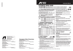
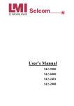
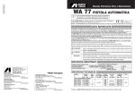
1
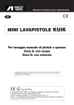
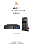
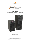
Operating and Maintenance Manual
SPRAY GUN WASHER
INOX HOT H2H
Mod. H2H
Before use, adjustment or maintenance, it is important to
read this instruction manual very carefully. The manual
must be stored in a safe place for any future reference that may
be necessary.
GB
SPRAY GUN WASHER INOX HOT H2H Mod. H2H
TABLE OF CONTENTS
1.
1.1
1.2
1.2.1
1.2.2
1.3
1.4
1.5
1.6
1.7
INTRODUCTION ..........................................................................................................................................3
GUARANTEE................................................................................................................................................3
APPLICATION ..............................................................................................................................................4
IMPROPER USAGE......................................................................................................................................4
WASHING PRODUCTS ................................................................................................................................4
THE CE CERTIFICATION OF THE SPRAY-GUN WASHER ......................................................................5
DESCRIPTION..............................................................................................................................................6
IDENTIFICATION ........................................................................................................................................10
TECHNICAL SPECIFICATIONS ................................................................................................................10
SOUND LEVEL ..........................................................................................................................................11
2.
2.1
2.2
2.3
2.4
2.5
2.6
2.7
GENERAL RULES FOR SAFETY AND ACCIDENTAL PREVENTION ....................................................11
DANGER LEVELS AND TERMINOLOGY ................................................................................................11
WORKWEAR ..............................................................................................................................................12
ECOLOGY AND POLLUTION....................................................................................................................12
DANGER PLATES AND SIGNALS ............................................................................................................13
STANDARDS FOR SAFE OPERATION ....................................................................................................14
SAFE MAINTENANCE ..............................................................................................................................15
DEMOLITION AND DECOMMISSIONING ................................................................................................16
3.
SHIPMENT AND UNLOADING ..................................................................................................................16
4.
4.1
4.2
4.3
4.3.1
4.3.1.1
4.3.1.2
INSTALLATION ..........................................................................................................................................16
POSITIONING ............................................................................................................................................16
CHECKS BEFORE EQUIPMENT INSTALLATION....................................................................................16
INSTALLATION ..........................................................................................................................................17
CONNECTIONS..........................................................................................................................................17
PNEUMATIC SYSTEM ..............................................................................................................................17
ELECTRIC SYSTEM ..................................................................................................................................18
5.
5.1
5.2
5.3
INSTRUCTIONS FOR USE ........................................................................................................................19
WATER HEATING CONTROL PANEL ......................................................................................................19
PREPARATION FOR THE USE OF THE SPRAY-GUN WASHER ............................................................20
WASHING GUNS AND ACCESSORIES WITH WARM WATER ................................................................20
6.
SEPARATING PAINT FROM WATER ........................................................................................................20
7.
7.1
7.1.1
7.2
SPRAY-GUN WASHER SYSTEMS ............................................................................................................21
HYDROPNEUMATIC SYSTEM ..................................................................................................................21
OPERATION ..............................................................................................................................................22
ELECTRIC DIAGRAM ................................................................................................................................22
8.
SAFETY DEVICES ....................................................................................................................................24
9.
9.1
9.2
9.3
9.4
MAINTENANCE AND PERIODICAL CHECKS ........................................................................................24
ORDINARY MAINTENANCE......................................................................................................................25
INSUFFICIENT VAPOUR EXHAUST..........................................................................................................25
CLEANING THE SMALL VENTURI PUMP ................................................................................................26
CLEANING THE NEBULIZER ....................................................................................................................26
10.
SPARE PARTS LIST ..................................................................................................................................27
ANEST IWATA EUROPE srl reserves the property of the following manual. Any reproduction or disclosure of this manual
without prior approval by the owner is expressly prohibited. For any claims, accidents or the like, the legally approved text
will be the one in the manufacturer's language. ANEST IWATA EUROPE waives any and all liabilities for damages by misinterpretations or incorrect use caused by imperfect or imprecise translations.
2
SPRAY GUN WASHER INOX HOT H2H Mod. H2H
1. INTRODUCTION
This manual contains the instructions for the installation, use and maintenance of the washing equipment SPRAY GUN WASHER
INOX H2H referred hereinafter simply as Spray-gun Washer. This manual is an integral part to the product and should be kept
with the due care in order to allow for its use and consultation during the life of the Spray-gun Washer.
The regular operation, economy and safety of the Spray-gun Washer depends on the compliance with the instructions given in this
manual. In case of loss or deterioration, submit your request for extra copies to:
ANEST IWATA EUROPE S.r.l.
Corso Vigevano 46 - 10155 Torino
TEL.+39 011-24 80 868 - FAX.+39 011-22 74 406
Web: www.anest-iwataeu.com - E-mail: [email protected]
The regular operation, economy and safety of the Spray-gun Washer depends on the compliance with the instructions given in this
manual. It is mandatory to follow the procedures as described in this manual:
This manual must be thoroughly read and understood before installing, using and operating or servicing
the machine. The Spray-gun Washer must be used only to wash spray guns or small parts stained with
water-based paint using warm water and special water-based detergents. All other uses of the Spraygun Washer not covered by this manual are to be considered inappropriate and are strictly forbidden.
ANEST IWATA EUROPE declines any and all responsibility for damage to persons, animals and property
deriving from improper use of the Spray-gun Washer or from failure to observe the instructions in this
manual.
The machine is supplied with an electric system with IP65 protection class in compliance with the EN 60529 norm and the following
features:
First digit 6: sealing against dust penetration.
Second digit 5: protection against strong water jets in any direction
•
•
1.1 GUARANTEE
Upon delivery of the Spray-gun Washer, it is necessary to make sure that no damages have occurred during shipment and the supply of accessories is complete and undamaged. Claims must be filed within 8 days of delivery. The buyer is eligible for the guarantee coverage only when he has complied with the guarantee conditions listed below.
La ANEST IWATA EUROPE guarantees its products under the following conditions:
a)
The Spray-gun Washer is guaranteed for a period of one year from the date of purchase as certified by a delivery document
issued by the Dealer. When the customer requests guarantee service, he must always specify the model, serial number and
year of manufacture of the appliance.
b)
The guarantee covers free replacement or repair of the appliance component parts which are recognized to have manufacturing defects without any charge for labour.
c)
Guarantee services are performed at the manufacturer's factory or at authorized service centres. The appliance must be sent
already prepaid to them and shall be returned to the customer at his own expense and risk. If any intervention by technicians
is requested under guarantee coverage at the customer's installation site, then the customer shall be charged for the transfer
time, for mileage and for all board and lodging expenses according to the valid fees applied by the Service Centre. No charge is made for the time required to repair and replace parts.
d)
The manufacturer waives all liability for any damage that may directly or indirectly be caused to persons or property resulting
from failure to comply with all the provisions in the instruction manual. In particular, this regards failure to comply with warnings
about placing, installing, operating and maintaining the appliance. The present guarantee does not cover any reimbursement
for direct or indirect damage due to appliance down-time. Guarantee coverage is only valid when payments are all in due order.
e)
This agreement is governed by current law in the Republic of Italy. Any controversy deriving from this agreement shall be settled by the Court in Torino, Italy.
3
SPRAY GUN WASHER INOX HOT H2H Mod. H2H
In addition to the cases stated above, guarantee coverage is waived in the following cases:
• Whenever the Spray-gun Washer has been handled or operated incorrectly by the operator.
• Whenever the damage is due to insufficient maintenance.
• Whenever the Spray-gun Washer has been damaged by modifications following repairs done without ANEST IWATA EUROPE's
consent or the installation of non-original spare parts.
• Whenever the owner/operator fails to comply with the instructions given in this manual.
• Whenever corrosive detergents are used that do not comply with legal standards or not included among those listed by
ANEST IWATA EUROPE.
1.2 APPLICATION
The Spray-gun Washer has been designed and built only to wash spray guns or small parts stained with water-based paint using
warm water and specific water-based detergents. The weight of pieces to be washed should not exceed 10 kg weight.
1.2.1 IMPROPER USAGE
All other uses not covered or non-complying with this manual are to be considered improper and are strictly forbidden.
The following uses are not allowed:
• It is forbidden to wash objects or products not covered by this manual.
• It is forbidden to wash Spray-guns or small parts using detergents with technical specifications different from those included in
this manual.
• It is forbidden to use inflammable solvents for any purposes.
• It is forbidden to use the Spray-gun Washer within environments in which potentially explosive gas mixtures, vapours or dusts
may occasionally generate.
WARNING
The Spray-gun Washer must be used exclusively for the purpose for which it was designed and built.
All other uses not covered by this manual are to be considered inappropriate and are strictly forbidden.
ANEST IWATA EUROPE declines any and all responsibility for damage to persons, animals and property
deriving from improper use of the Spray-gun Washer and/or from failure to observe the instructions in
this manual.
Given the fact the Spray-gun Washer is an appliance manufactured to wash Spray-guns using clean water and water-based detergents, i.e. free from flammable components, there are no restrictions as regards the surface area occupied by the Spray-gun Washer
and the machines positioned near it.
1.2.2 WASHING PRODUCTS
Spray-guns and accessories can be washed using:
• Clean water
• Water with “AQUA REVIVE” detergent by ANEST IWATA EUROPE, or
• Water-based liquid detergent with the following specifications: pH ranging from 6.5 and 12; exclusion of flammable components
or, if any, not exceeding 8%.
The above products must comply with the anti-pollution regulations provided by the law in force in the Country where the Spray-gun
Washer is used.
WARNING
It is forbidden to use solvent or any other flammable product to wash Spray-guns.
4
SPRAY GUN WASHER INOX HOT H2H Mod. H2H
1.3 THE CE CERTIFICATION OF THE SPRAY-GUN WASHER
Directive 98/37/EC stresses the minimum requirements machinery must be brought in line with, in order to be placed on the
European Union market. All machinery covered by this Directive may be placed on the market and put into service only if they do
not endanger the health and safety of persons, domestic animals or property. The Spray-gun Washer is a machine designed to wash
Spray-guns and is not included in any of the categories indicated in the list attached to the Directive (Annex IV - highly dangerous
machinery). Prior to placing its machines on the market and in order to demonstrate that the machines are in compliance with the
provisions set forth by Directive 98/37/EC, ANEST IWATA EUROPE guarantees that all the tests and controls required by the reference regulations (including the risks analysis) have been conducted and meet the essential safety and health requirements as provided for by Annex I of the aforementioned Directive. The technical construction file that includes the fundamental project data and
all the specifications relating to the machine safety has been drawn in compliance with Annex V of Directive 98/37/EC, and is made
available to any controls by the inspection authorities - prior to detailed notification, as provided for by the ruling provisions in this
matter. Given that the machine has been designed and built in compliance with the provisions set forth by directive 98/37/EC, and
can be safely operated under the conditions stated by this manual, ANEST IWATA EUROPE puts the Spray-gun Washer on the
market provided with:
• CE Mark
• EC Declaration of Conformity
• Instructions for use (User's Manual)
ANEST IWATA EUROPE guarantees that the Spray-gun Washer design and construction comply with the requirements set forth
by the application of the European legal provisions referring to this matter, and precisely with the following directives:
• Directive 89/336/EEC and subsequent additions (Electromagnetic compatibility)
• Directive 98/37/EC (Safety of Machinery).
• Directive 2006/95/EC (Low voltage)
The following European standards and technical norms have been used by the manufacturer and can be a reference in order to
verify the conformity with the legal European provisions:
- EN 294:1992: SAFETY OF MACHINERY - Safety distances to prevent danger zones being reached by the upper limbs.
- EN 349:1993: SAFETY OF MACHINERY - Safety of machinery. Minimum gaps to avoid crushing of parts of the human body.
- EN 418:1993: SAFETY OF MACHINERY - Emergency stop equipment - Functional aspects - Principles for design.
- EN 614-1:1995: SAFETY OF MACHINERY - Ergonomic design principles. Part 1: Terminology and general principles.
- EN 842:1996: SAFETY OF MACHINERY - Visual danger signals. General requirements, design and testing.
- EN 954-1:1996: SAFETY OF MACHINERY - Safety-related parts of control systems - Part 1: General principles for design.
- EN 983:1996: SAFETY OF MACHINERY - Safety requirements for fluid power systems and their components. Pneumatics.
- EN 1050:1996: SAFETY OF MACHINERY - Principles for risk assessment.
- EN ISO 3746:1995: ACOUSTICS - Determination of sound power levels of noise sources using sound pressure - Survey method using an enveloping measurement surface over a reflecting plane.
- ISO 7000:1995 GRAPHICAL SYMBOL FOR USE ON EQUIPMENT - Index and synopsis.
5
SPRAY GUN WASHER INOX HOT H2H Mod. H2H
- EN ISO 11202:1995: ACOUSTICS - Noise emitted by machinery and equipment - Measurement of emission sound pressure
levels at a work station and at other specified positions - Survey method in situ.
- EN ISO 12100-1:2003: SAFETY OF MACHINERY - Basic concepts, general principles for design
Part 1: Basic terminology, methodology.
- EN ISO 12100-2:2003: SAFETY OF MACHINERY - Basic concepts, general principles for design
Part 2: Basic terminology, methodology.
- EN ISO 12100-2:2003: SAFETY OF MACHINERY - Basic concepts, general principles for design
Part 2: Basic terminology, methodology.
- EN 12921-1:2005: MACHINES FOR SURFACE CLEANING AND PRE-TREATMENT OF INDUSTRIAL ITEMS USING LIQUIDS
OR VAPOURS - Part 1: Common safety requirements.
- EN 12921-2:2005: MACHINES FOR SURFACE CLEANING AND PRE-TREATMENT OF INDUSTRIAL ITEMS USING LIQUIDS
OR VAPOURS - Part 2: Safety of machines using water based cleaning liquids
- EN 55022:1998: CISPR 22 - Information technology equipment. Radio disturbance characteristics. Limits and methods of measurement.
- EN 60204-1:2006-06: SAFETY OF MACHINERY - Electrical equipment of machines. Part 1:General requirements.
- EN 60529: 1997 DEGREES OF PROTECTION PROVIDED BY ENCLOSURES (IP code)
- EN 61000-6-1:2001 ELECTROMAGNETIC COMPATIBILITY - Part 6-1: Generic standards - Immunity for residential, commercial and light-industrial environments.
- EN 61000-6-3:2001 ELECTROMAGNETIC COMPATIBILITY - Part 6-3: Generic standards - Immunity for residential, commercial and light-industrial environments.
1.4 DESCRIPTION
The pneumatic Spray-gun Washer with electrical water heating consists of a stainless steel container (see fig. 1A) designed to carry
out:
• A manual washing with warm detergent enabled by a small Venturi pump (pos.21 fig.1A).
• A final washing with clean water by means of a nebulizer (pos.22 fig.1A)
• A brush (pos.36 fig.1), connected to the workshop water system for the final washing of Spray-guns, for washing the collecting
container (pos.2 fig.1A) after having discharged dirty water, and to fill tanks once again with clean water (pos.2-W53 fig.1A).
• A grid top (pos.6C fig.1A) to drop and drain the Spray-guns to be washed.
• A heated sink (pos.2 fig.1) to collect the used detergent, and fitted with a mixing unit (pos.35 fig.1A) to mix coagulating powder.
• A tap (pos.30 fig.1A) to discharge the product and the coagulated paint in the filter (pos.W50 fig.1A).
• A tank (pos.W53 fig.1A) to collect filtered water.
The Spray-gun Washer is supplied with hoses (pos.7-23 fig.1A) for suction and discharge of the various liquids from the containers.
From the upper control panel, the operator can control:
• The small pump (pos. 19 fig. 1A) for warm detergent
• The clean water nebulizer (pos. 18 fig.1),
• Clean water from the workshop water system (pos.18C fig.1).
• The vapour exhaust (pos.41 fig.1).
• The regulation of the air flow for mixing water with coagulating powder (pos. 1 fig. 1)
6
SPRAY GUN WASHER INOX HOT H2H Mod. H2H
Description of the Spray gun washer (See fig. 1A-1B):
1
2
3
4
4A
6C
7
7F
10
11A
12
15
16
18
18C
19
21
22
22C
23
23C
23R
30
35
36
41
W50
W51
W52
W53
74
76
80
81
82
83
84
85
86
87
88
89
90
91
92
93
94
95
96
97
98
99
Regulator valve of mixing air flow
Heated tank for collecting liquids
Lower door magnet
Spray-gun feeding hose
Blowing gun
Grid top
Small pump feeding hose
Small pump feeding filter
Air outlet fitting
Lower door
Air inlet fitting with filter
Vapor exhaust nozzle
Vapor stack (ø 120 mm)
Nebulizer check valve
Water control lever connected to the water mains.
Check valve of warm water small pump
Warm water small pump
Nebulizer
Water outlet fitting
Nebulizer feeding hose
Water inlet fitting
Water flow regulation valve (to be connected to the fitting 23C and the water mains).
Sink discharge valve
Air diffuser to mix water and coagulating powder
Washing brush
Exhaust command valve
Pre-filter bag
Filter bag
Pierced container
Clean water container
External earth cable
Rear pipe guide
Electrical panel
Power supply cable
Pierced screw
Sink bottom protection
Sink bottom fitting
Electric resistance
Operating sensor and safety sensor
Probe bracket locking nut
Thermal insulation
Resistance protection
Protection reinforcement
Protection locking nut
Max temperature thermostat
Internal earthing cable
Resistance power supply cable
Rear cover
Probe cable
Small thermal insulation
Probe brackets
Packing and forwarding protection to be removed before installation
7
SPRAY GUN WASHER INOX HOT H2H Mod. H2H
Figure 1A
NB. When ordering spare parts, always indicate:
MODEL - SERIAL NUMBER - CONSTRUCTION YEAR
8
SPRAY GUN WASHER INOX HOT H2H Mod. H2H
Figure 1B
NB. When ordering spare parts, always indicate:
MODEL - SERIAL NUMBER - CONSTRUCTION YEAR
9
SPRAY GUN WASHER INOX HOT H2H Mod. H2H
1.5 IDENTIFICATION
(See fig. A)
Every spray gun washer has a CE identification plate that shows:
ABCDEFGHILM-
Manufacturer's brand.
Maximum Working Pressure
Manufacturer's name and address
CE Mark.
Max Amount of washing product
Protection Level
Year of manufacture
Voltage
Serial number
Electric Supply
Model
N.B.: The G - I - M data listed in the identification plate must be always specified when calling for service and/or supply
of spare parts.
C
A
D
B
E
F
G
M
L
I
H
Fig. A
1.6 TECHNICAL SPECIFICATIONS
Description
Mass (Weight).
Dimensions of the Spray gun washer
Height
Width
Depth
Max operating pressure
Feeding air operating pressure.
Recommended pressure once the SPRAY-GUN WASHER is ON.
Diameter of the holes of the suction nozzle (pos.15 fig.1A).
(Mean) Air consumption at 6 bar.
Fume chute diameter (pos.16 fig.1A).
Air speed at hood entrance (8 bar).
Air capacity at chute exit ( 8 bar).
Stainless steel sink water capacity (pos.2 fig.1A).
Lower container capacity (pos.W53 fig.1A).
Voltage/frequency.
Electric resi stance
Temperature of detergent inside sink (pos.2 fig.1A)
Electric system protection level
10
Unit of Measure
Value
kg
43
mm
mm
mm
bar
bar
bar
mm
Nm3/h
mm
m/sec
m3/h
dm3(litres)
dm3(litres)
V/Hz
W
°C
-
1410
450
670
10
6˜10
8
1,5
9
120
0.51
366
50
70
230/50
980
38-44
IP 65
SPRAY GUN WASHER INOX HOT H2H Mod. H2H
1.7 SOUND LEVEL
The sound level emitted by the Spray gun washer has been measured under working conditions using a sound level meter with integrator. Measures were taken by a skilled laboratory technician in accordance with EN ISO standard 3746. Results are as follows:
• Acoustic pressure equivalent average level:
LpAm = 78,2 dB (A)
• Acoustic pressure level at the operating post: LpA = 85,9 dB (A)
• Conventional Acoustic pressure level:
LwA = 93,1 dB (A)
2. GENERAL RULES FOR SAFETY AND ACCIDENTAL PREVENTION
2.1 DANGER LEVELS AND TERMINOLOGY
The safety of both the operator and the persons exposed to the machinery is the primary concern of the designer and builder of the
machine. In designing a new Spray gun washer, every attempt is made to prevent any possible situation of danger and risks connected with use of the machine, by applying the appropriate solutions to make the equipment as safe as possible. It is therefore
recommended that you read this manual carefully, especially this section, which concerns the safety norms, and that you avoid inopportune behaviour or behaviour that is contrast with the instructions contained herein.
Pay attention to the hazardous warnings indicated in this Manual and comply with all the safety provisions.
There are three severity levels of hazards:
DANGER
This signal communicates that improper performance of the procedures herein will result in severe injuries, death or prolonged medical treatments. The DANGER signal is used for extreme hazardous levels
WARNING
This signal communicates that improper performance of the procedures herein could result in severe
injuries, death or prolonged medical treatments. The WARNING signal is used for lower levels of hazard
than in DANGER.
CAUTION
This signal communicates that improper performance of the procedures herein could damage the machine. The CAUTION signal is used for a lower level of hazard than in DANGER and WARNING.
Read carefully the following standards. Failure to comply could result in personal injuries or damages to persons, animals and property.
ANEST IWATA EUROPE waives all liability for any damage that may directly or indirectly result from failure to comply with the safety and accident prevention standards herein. ANEST IWATA EUROPE also
declines all liability for damage caused by improper use of the SPRAY-GUN WASHER and/or modifications to the machine made without the manufacturer's authorisation.
11
SPRAY GUN WASHER INOX HOT H2H Mod. H2H
TERMINOLOGY: The following definitions are provided for the terminology used in this manual. The correct explanation of this terminology is necessary to ensure perfect understanding of situations of danger that could arise while using the machine with direct
effects for the operator, and the persons exposed to the machine itself:
• OPERATOR:
In a general sense, the person in charge of transporting, installing, adjusting, operating, cleaning and performing ordinary maintenance on the SPRAY-GUN WASHER (Art. 1.1.1., para. 1, attachment I, directive 98/37/EC).
• EXPOSED PERSON:
Any person next to or inside a dangerous area, for any reason whatsoever (Art. 1.1.1., para 2, attachment I, directive 98/37/EC).
• DANGEROUS AREA:
Any area next to or inside the machine, where the presence of an exposed person constitutes a risk for the safety and health of
said person (Art. 1.1.1., para 3, attachment I, directive 98/37CE).
• OPERATOR:
The person, organisation or company responsible for the training of workers who must operate the equipment, which has purchased the SPRAY-GUN WASHER in any form or has rented the equipment, which must be used only for the purposes intended
by the manufacturer.
• SPECIALISED TECHNICIAN:
An especially trained and qualified person to perform maintenance intervention or repairs, which require special in-depth knowledge of the machine, its operation, safety devices, dangerous areas and methods of intervention, who is therefore capable of
recognising and avoiding dangers arising from use of the machine.
• pH:
Measurement that expresses the acidity of a solution. The pH scale ranges from 0 to 14. For pure water the pH value = 7.
When pH is above 7 the solution in alkaline; when it is less than 7 the solution is acid.
2.2 WORKWEAR
The type of workwear depends on the work that must be carried out. When using the SPRAY-GUN WASHER and relevant products,
comply with the regulations below:
• The operator must wear solvent-proof rubber gloves to prevent contact between his hands and the products used for washing.
• The operator must always wear protective eyewear to prevent the solvent coming into contact with his eyes.
• The operator must use a protective mask to avoid inhaling gas and dust.
2.3 ECOLOGY AND POLLUTION
• The Spray gun washer must not be used to wash or degrease objects designed to come into contact with foodstuffs.
• Comply with Laws in the country where the Spray gun washer is installed regarding use and disposal of washing products
and with the recommendations given by the manufacturer of these products.
12
SPRAY GUN WASHER INOX HOT H2H Mod. H2H
2.4 DANGER PLATES AND SIGNALS
The Spray gun washer carries the manufacturer's identification plate as well as pictograms (labels) that warn against any machine's
residual risks that may occur. Figure 2 indicates the danger signs and signals and shows where the Manufacturer's identification
plate is normally placed.
These warning signals have the following meanings:
1.
Manufacturer's identification plate: Manufacturer's brand, CE mark, model, serial number and year of construction, air pressure, max quantity of washing product, power supply specifications, voltage, level of protection.
2. General danger.
3. Warning: It is mandatory that you carefully read the instructions manual before operating the machine.
4. Warning: It is forbidden to use open flames and to smoke near the Spray-gun Washer.
5. Warning: It is mandatory that you put on a protective mask before working with the machine.
6. Warning: It is mandatory that you put on solvent-proof rubber gloves before you start working.
7. Warning: It is mandatory that you put on protective eyewear before you start working.
8. Danger: It is mandatory that you power off the machine and disconnect the compressed air supply before starting any maintenance or repair operations in the Spray gun washer.
9. Warning: It is mandatory that you check hoses ensuring they are well fitted in the drums before starting any operation.
10. Caution: It is recommended that you check the water level in the containers periodically to avoid overflows.
11. Burning danger: It is forbidden to carry out any operation inside the empty sink (pos.2 fig.1A) when the machine is on.
12. Warning: It is mandatory that you power off the machine before discharging water from the sink (pos.2 fig.1A).
1.
11.
12.
Figure 2
13
SPRAY GUN WASHER INOX HOT H2H Mod. H2H
2.5 STANDARDS FOR SAFE OPERATIONS
The SPRAY-GUN WASHER has been designed and built to be used in ventilated environments where potentially explosive atmospheres from gas mixture, vapours of powder are not to be expected.
The use of the Spray-gun Washer is strictly forbidden to anyone who has not fully read and understood the contents of this
instruction manual
•
• It is strictly forbidden to let the Spray-gun Washer be used by anyone who is not properly skilled or duly trained or is not in perfect health.
• It is forbidden to use the Spray-gun Washer following instructions which are not included in the final application: the appliance
must be used exclusively to wash Spray-guns, small containers and objects stained with water-based paint.
• It is forbidden to use detergents or products which do not comply with the specifications included in this manual, and with the
law during the washing cycle.
• It is forbidden to use detergents having pH values lower than 6.5 or exceeding 12. If the mixture contains flammable substances, their quantity must be limited to 8%.
• It is forbidden to use solvents or other flammable products.
• It is forbidden to put unsuitable objects and weights above 10 Kg on the grid top (pos. 6C fig.1) of the Spray-gun Washer.
• It is forbidden to run the machine once it has been powered on, without the internal protection (pos. 83 fig. 1B) and external protections (pos.89-95 fig.1B).
• It is forbidden to run the machine once it has been powered on, without liquid inside the sink (pos. 2 fig. 1A).
• It is forbidden to drain the detergent from the sink (pos. 2 fig.1A) before the machine has been powered off from the control panel
(pos. 80 fig. 1A).
• It is forbidden to continually disconnect and reconnect the air supply hose from its connection (pos.12 fig.1A).
• It is forbidden to use the Spray-gun Washer in environments where potentially explosive atmospheres formed by mixtures of
gas, vapour or dust may be occasionally expected and for very short periods.
• It is forbidden to connect the electric system of the Spray-gun Washer directly to the electric system conductors: a failure may
result in injuries or damage the control panel.
• It is forbidden to make any junctions along the power cable.
• It is forbidden to run the machine when pictograms communicating danger (self-adhesive labels) applied to the machine are missing or damaged. If this is the case, immediately replace them with other labels with the same meaning.
• It is forbidden to perform cleaning or ordinary maintenance operations when the Spray-gun Washer
is powered on and ready to
be used: power off the machine before any such operations.
• It is forbidden to weld, flame cut or perforate the Spray-gun Washer case.
• It is mandatory that you position the machine within a facility providing shelter against water and ice: the Spray-gun Washer has
been designed to work only indoor.
• It is mandatory that before using the Spray-gun Washer all safety devices be checked for integrity.
• It is mandatory that before using the Spray-gun Washer, you connect the external ground wire (pos 74 fig. 1A) to the workshop
mains.
• It is mandatory that, while loading and unloading the container, you pay attention not to spill the solvent on the workshop floor.
• It is mandatory that, before using the Spray-gun Washer, the water feeding hoses (pos.7-23 fig.1A), are firmly inserted in their
respective containers - being careful not to bend them. Make sure that they are not damaged before using the Spray-gun Washer.
• It is mandatory
that, before using the Spray-gun Washer you ensure that the cover (pos.46-95 fig. 1A-1B) closes perfectly the
inspection hole
• It is mandatory that you clean periodically the grid top (pos.6C fig.1A).
• It is mandatory that you power off the machine from the control panel (pos. 80 fig. 1A) before draining the detergent from the sink
(pos. 2 fig. 1A).
• It is mandatory that, to avoid overflows, you periodically check that the water level in the sink (pos. 2 fig. 1A) is not above its normal level.
• It is mandatory that, at least once a month, you empty the dirty water container (pos. 2 fig. 1A) and you clean the bottom of the
sink removing thoroughly sludge to avoid incrustations.
14
SPRAY GUN WASHER INOX HOT H2H Mod. H2H
• It is mandatory that you have the Spray-gun Washer serviced only by qualified, skilled and competent personnel in compliance
with the instructions included in this manual.
• It is mandatory that you verify the earth cable of the Spray-gun Washer after connection to the electric system. A failure or incorrect connection of the earth cable may result in severe injuries and ultimately death.
• It is recommended that you don't have nylon, plastic, glass wool, GRP or similar products next or over the Spray-gun Washer to
avoid electrostatic charges.
• It is recommended that, before operating the machine, you become familiar with the control devices and their functions.
• It is recommended that , should skin or eyes come in contact with washing products, you rinse them abundantly with water.
• It is recommended that, if the Spray-gun Washer remains unused for a long period of time, you empty the dirty water sink (pos.
2 fig. 1A) and rinse the washing sink (pos. 2 fig. 1A) with clean water.
• It is recommended that you replace the dirty detergent whenever needed: you can
regenerate it with the coagulating powder
and the appropriate kit, or hand it to waste recovery companies.
• It is recommended that, before discharging the dirty detergent from the sink (pos. 2 fig. 1A) through the valve (pos. 30 fig. 1A),
you ensure that the 2 containers (pos. W52-W53 fig. 1A), the prefilter (pos. W50 fig. 1A) and the filter (pos. W51 fig. 1A) are positioned below. Open the discharge valve (pos. 30 fig. 1A) and drain slowly the dirty water to avoid overflows.
DANGER
It is forbidden to spray and/or blow with the gun pointed to the operator or other persons:
THIS COULD CAUSE SERIOUS DAMAGE TO HEALTH.
2.6 SAFE MAINTENANCE
The directions below guarantee the ideal performance and safe operations of your Spray-gun Washer.
• It is forbidden to remove or tamper safety devices.
• It is forbidden to carry out cleaning, lubrication, greasing or ordinary maintenance when the machine is powered on and ready
for use: disconnect the electric power and compressed air supply before any such operations.
• It is forbidden to weld, flame cut or perforate the structure.
• It is mandatory to check the safety devices for integrity when you start operating.
• It is mandatory to check periodically the preservation conditions of the hoses: they must not show cuts or clear signs of abrasions. If needed, immediately replace them with hoses of similar specifications.
• It is mandatory to clean the machine thoroughly, following the instructions contained in this manual, and to replace damaged or
worn out parts during maintenance.
• It is mandatory to have the machine serviced only by qualified, skilled and competent staff following the instructions contained
in this manual.
• It is mandatory to periodically check the pictograms of danger signals (self-adhesive labels): they directly provide essential communication of dangers and actions to undertake in order to avoid injuries or dangerous situations. They must be replaced when
missing or even partially damaged.
• It is recommended that you always use original spare parts during maintenance or repair operations.
• It is recommended that you store and keep this instructions manual for the entire lifespan of this machine.
15
SPRAY GUN WASHER INOX HOT H2H Mod. H2H
2.7 DEMOLITION AND DECOMMISSIONING
Upon demolition or decommissioning of the Spray gun washer, we recommend that you take the necessary precautions to avoid
danger to exposed persons and the risk of environmental pollution:
• Power off the Spray gun washer and disconnect the compressed air supply, and discharge the residual energy accumulated.
• Residual liquid possibly left in the sink and hoses of the equipment must be carefully drained.
• The other parts of the Spray gun washer must be treated in accordance with the regulations for special waste. Proceed by disassembling the machine: group the various units and parts into homogeneous lots and provide for their disposal separately, in accordance with environmental protection laws in the country where the machine is installed.
In general, please bear in mind that:
• Plastic or rubber parts are special waste.
• Ferrous scrap and carpentry are special waste.
3. SHIPMENT AND UNLOADING
The Spray gun washer is shipped in a carton with the markings < fragile > and < keep upright >. It is palletized and can be easily
handled with a fork lift to the installation area. Remove the cardboard and the pallet, and check that the machine has not been damaged during the transport.
4. INSTALLATION
4.1 POSITIONING
When deciding where to position and install the machine, you should carefully consider the points here below.
The machine must be positioned indoors in a safe, obstacle-free area, sheltered against weather conditions.
The area should be well-lighted
The environment must be suitable for housing the machine, and free from open flames, sources or processing systems that may
develop gas or flammable or explosive vapours. The IP65 protection electric system case of the Spray-gun Washer should not be
installed in environments where there might be releases of gas and/or flammable vapour or explosive mixtures
The Spray-gun Washer room temperature should be ranging from 15° to 45°C.
•
•
•
•
4.2 CHECKS BEFORE EQUIPMENT INSTALLATION
Before installation, check and, if needed, adjust the workshop technical systems.
WARNING
Max air pressure should never exceed 10 bar. Should the safety valve of the workshop compressor run
at a higher pressure, the SPRAY-GUN WASHER must be installed with a filter-regulator- pressure reducer unit provided with a manometer and regulate pressure at 8 bar.
• Compressed air pressure must not be lower than 6 bar. If not, an air backup tank should be installed in order to guarantee a mini•
•
•
16
mum operating function of the Spray-gun Washer.
Proceed by checking voltage and operating frequency: they must correspond to the power supply voltage and frequency of the
workshop.
The operating voltage of the Spray-gun Washer is included in the technical specifications. The electric system is designed to operate at 220 volt voltage, 50 hertz single-phase frequency.
Check the power supply panel feeding the Spray-gun Washer: it must be fitted with fuses circuit and/or an appropriately calibrated magneto-thermal switch, and a differential circuit breaker (cut-out switch).
SPRAY GUN WASHER INOX HOT H2H Mod. H2H
DANGER
It is forbidden to connect the electric system directly to the connectors of the power supply system: a
failure may result in injury or damage the control panel.
WARNING
All the following operations of installation, adjustment and testing must be carried out exclusively by
qualified and responsible personnel who can guarantee application of safety standards in the mechanical and compressed air fields.
4.3 INSTALLATION
The correct installation of the Spray-gun Washer depends on the air speed at the entrance of the suction hood. Given the fact that
this value indicated under 1.5 TECHNICAL SPECIFICATIONS - is influenced by the length and shape of the fume chute, a long or
non-upright chute, with section reductions or long horizontal sections, will decidedly decrease the exhaust capacity and increase the
concentration of vapours in the washing area. Therefore, follow carefully the instructions below.
4.3.1 CONNECTIONS
WARNING
Ensure that connections are made with the greatest care. We recommend that you follow the instructions
below and the functional diagrams included in the manual.
4.3.1.1 PNEUMATIC SYSTEM
Comply with the following instructions when installing the Spray-gun Washer:
• Remove the cardboard packing (pos.99 fig.1B).
• Extend the discharge hose (pos.16 fig.1A) insert it into the hole on top of the Spray-gun Washer and put it in upright position for
•
at least 1 meter; finally connect it to the outside of the workshop. If the outlet hole is over 2 metres away, it is recommended that
you use a 12 cm diameter galvanized pipe (no plastic), with the elbow as distant as possible from the Spray-gun Washer (see
figure AS).
Example: if the outlet hose is 5 metres long, at least 3-4 metres should be upright, and 2-1 metres horizontal.
Avoid putting 1metre vertically and 4 metres horizontally.
Connect the gun feeding hose (pos.4 fig.1A) to the fitting (pos.10 fig.1A).
Connect the filtered air feeding hose to the fitting (pos.12 fig.1A), through a 8 mm (minimum) hole. It is recommended that you
use a fast-on air inlet fitting, to facilitate periodical lubrication (3-4 times yearly) with oil for nebulizers.
Figure AS
17
SPRAY GUN WASHER INOX HOT H2H Mod. H2H
4.3.1.2 ELECTRIC SYSTEM
WARNING
Connect the electric system to the control panel of the Spray-gun Washer.
Follow the instructions below, when you are ready to connect the electric system of the Spray-gun Washer to the workshop electric
power system:
• First, start by checking the voltage and the operating frequency: they must correspond to the voltage and frequency of the mains
•
•
in the workshop. The plate located onto the machine case indicates the operating voltage of the Spray-gun Washer which is designed to work under single-phase 220 volt, 50 hertz voltage.
Check the switchboard feeding the Spray-gun Washer: it must be provided with three fuses and/or magneto-thermal switch and
an appropriate differential switch (cut-out switch).
ANEST IWATA EUROPE also supplies a 3-metre long cable with a 6 mm2 section for a 2-pole + earthing connection to the mains.
This length is enough to make almost all kind of connections. If the cable supplied is not long enough to power the Spray-gun
Washer, you must replace it with a new longer cable.
WARNING
It is forbidden to lengthen (junction) the electric cable.
• The section of the electric cable must be suitable for the load absorbed
by the Spray-gun Washer and the distance between the
electric control panel and the electric switchboard.
DANGER
It is forbidden to connect the electric system of the Spray-gun Washer to the conductors of the workshop
system: a failure of the mains system may result in irreversible damages to the Spray-gun Washer and
severely injury the operator.
Check that the electric connection to the mains is correct according to the instructions below (fig. 4):
• Plug in the power cable in the appropriate socket.
• Rotate the feeding switch knob (pos. 80A) on the control panel until <ON>: the display (pos. 80B) must light up. If not, proceed by
checking carefully the connections.
DANGER
It is mandatory that you check the Spray-gun Washer earthing for efficiency after the connection has
been completed. A faulty or improper connection of the earth cable may result in severe injuries and ultimately death.
18
SPRAY GUN WASHER INOX HOT H2H Mod. H2H
5. INSTRUCTIONS FOR USE
The following instructions must be read and fully understood before starting to work with the Spray-gun Washer. With the Spray-gun
Washer.
5.1 WATER HEATING CONTROL PANEL
80A
80B
80C
80D
Main feed switch
Temperature display
Resistence ON red led
TIMER preset stop button (12 hours)
80E
80F
80G
80G
81
START key button (permanent mode)
STOP key button
STOP steady red led
EMERGENCY lighting red led
Electric supply cable
Figure 4
Before enabling any control on the panel, ensure the plug has been correctly connected (and grounded) to the workshop mains.
Make sure the sink (pos. 2 fig. 1A) contains 15-20 litres of washing liquid.
Turn on the safety switch (pos. 80 fig. 4) to power the control panel, and select two different operating modes:
• TIMER mode: Press the TIMER key button (pos. 80D fig. 4) to feed the resistance (pos. 85 fig. 1B) uninterruptedly for 12 hours
from its start. At the end, the heating will automatically stop.
• START mode: Press the START key button (pos.80E fig.4) to feed the resistance (pos.85 fig.1B) permanently.
Press the STOP key button (pos.80F fig.4) to interrupt heating.
You can change mode by pressing the STOP key button (pos.80F fig.4). The display (pos.80B fig.4) will show the temperature of
the liquid in the sink (pos.2 fig.1A): a red led (pos.80C fig.4) lights up when the resistance is working and is heating the liquid.
At the end of each work day, we recommend that you turn off the control panel by means of the lever (pos.80A fig.4).
WARNING: WHEN THE RED LED (Pos.80G Fig.4) IS FLASHING, THE SPRAY-GUN WASHER IS UNDER EMERGENCY
If the red led (pos.80G fig.4) lights up and flashes, it means that the electric resistance (pos.85 fig.1B) has been started despite no
washing liquid had been poured into the sink (pos.2 fig.1A).
Pour 15-20 litres of washing liquid and press the TIMER or START key buttons.
If the red light (pos.80G fig.4) lights up and immediately starts to flesh, contact the ANEST IWATA EUROPE company.
19
SPRAY GUN WASHER INOX HOT H2H Mod. H2H
WARNING
It is forbidden to tamper with the electric panel (pos.80 fig.1A) and to modify the applications pre-defined
by ANEST IWATA EUROPE , including the default temperature value (44°C) assigned to the detergent.
WARNING
In case of emergency, zero the lever (pos.80A fig.4) in order to turn off power at the entire panel (pos.80
fig.1A) and resistance (pos.85 fig.1B).
5.2 PREPARATION FOR THE USE OF THE SPRAY-GUN WASHER
• Pour 20 litres of detergent in the sink (pos.2 fig.1A), and 30 litres of clean water in the container (pos.W53 fig.1A), and insert the
hose (pos.7 fig.1A) in the sink (pos.2 fig.1A) and the hose (pos.23 fig.1A) in the sink (W53 fig.1A).
• From the control panel (pos.80 fig.1A) start the heating of the detergent poured in the sink (pos.2 fig.1A).
5.3 WASHING OF GUN AND ACCESSORIES WITH WARM WATER
With the first wash, clean the parts with a brush using the warm detergent of the small pump (pos.21 fig.1A) controlled by the valve
(pos.19 fig.1A). Pull the trigger of the Spray-gun and spray the detergent inside.
With the second wash, use the clean detergent from the nebulizer (pos.22 fig.1A) controlled by the valve (pos18 fog.1A).
For the final wash, use the washing brush (pos.36 fig.1A) connected to the water system of the workshop.
Pull the trigger of the spray gun and with the gun (pos.4 fig.1A) blow inside the duct conveying the paint and outside all along the
gun for the final drying.
WARNING
MAKE SURE that the level of the paint-dirty detergent inside the collecting sink (pos.2 fig.1A) does never
exceed the grid top (pos.6C fig.1A), and the quantity is never less than 15 litres.
WARNING
If the small pump (pos.21 fig.1A) doesnt suck warm detergent, most probably there is not sufficient liquid
in the sink (pos.2 fig.1A).
6. SEPARATING PAINT FROM WATER
Follow the instructions below:
The use of warm water improves the final result of the coagulation process and paint separation from water.
Turn off the heating in the sink (pos.2 fig.1A) from the control panel (pos.80 fig.1A/1B).
When the sink is full, remove the grid top (pos.6C fig.1A) from the sink, remove the filter from the water (pos.29F fig.1A) and place
it somewhere out of the sink.
Enable the regulating valve (pos.1 fig.1A), and mix the detergent in the sink (pos. 2 fig. 1A) with the air blowing out from the diffuser (pos.35 fig.1A).
While the product is in motion, pour slowly all over the water surface a dose (approximately 100 grams) of coagulating powder
and mix it for some 10 minutes. Shut off the air flow and ensure the paint is well coagulated. If not, repeat the procedure.
Open the regulator (pos.1 fig.1A) and, while both water and coagulated paint are in motion, open the discharge valve (pos.30
fig.1A) and let all the content out in the prefilter bag (pos.W50 fig.1A): proceed slowly to avoid any overflows.
Open entirely the water regulating valve (pos 23R fig.1A), open the valve (pos.18C fig.1A) and use the brush (pos.36 fig.1A) to
rinse the sink (pos.2 fig.1A).
•
•
•
•
•
•
20
SPRAY GUN WASHER INOX HOT H2H Mod. H2H
• After filtering the liquid, put the prefilter (pos. W50 fig. 1A) with the sludge in an external container ready to have it collected by a
water disposal company.
• If you decide not to coagulate the paint-dirty liquid, but to have disposed of by waste disposal companies, at each final wash the
•
water in the sink (pos. 2 fig. 1A) continues to increase, i.e. the detergent becomes thinner. This is the reason why we recommend
that you add a small quantity of detergent
For ideal coagulation: the detergent in the sink (pos. 2 fig. 1A) must never exceed 40% of the total liquid. Differently, when the sink
(pos. 2 fig. 1A) contains too much detergent or too much paint, the coagulation cannot be obtained unless you add extra water
and coagulating powder in that same sink. Once the coagulation has been completed, the liquid in the sink (pos.2 fig.1A) is filtered and conveyed into the container (pos.W53 fig.1A). This regenerated liquid can be re-used for the following cycle.
WARNING
It is mandatory to empty and rinse well the bottom of the sink (pos.2 fig.1A) at least once a month to
avoid incrustations.
7. SPRAY-GUN WASHER SYSTEMS
The Spray-gun Washer is an electro-pneumatic device.
The water contained in the sink (pos.2 fig.1A) is heated by means of an electric system connected and powered by the mains. The
other devices are controlled and operated by a compressed air system provided by the pneumatic system available in the workshop.
7.1 HYDROPNEUMATIC SYSTEM
1
2
3
4
5
6
7
8
9
Air filter
Throttle 1.8 mm
Blowing gun
3-way valve NC
Flow regulator
Blower (fume exhaust)
Valve (small pump control)
Small pump
Dirty water collecting container
10
11
12
13
14
15
16
17
18
(See fig. 5).
Valve (nebulizer control)
Nebulizer
Clean water container
Water inlet fitting
Ball valve (water regulation from the water system).
Ball valve (opens brush water flow)
Brush with water outlet from the water system).
Water and coagulating powder mixer.
Ball valve for water discharge
Figure 5
21
SPRAY GUN WASHER INOX HOT H2H Mod. H2H
7.1.1 OPERATION
Incoming compressed air is blown through filter (1), feeds throttle (2), the blowing gun (3), and the valve (4), and the flow regulator
(5). When the valve (4) is open it feeds the blowing nozzle (6). When the Venturi effect makes the valve (7) open, the small pump (8)
sucking dirty detergent from the sink (9) is enabled. When the Venturi effect makes the valve (10) open, the nebulizer (11), sucking
clean water from the container (12), is enabled. When the flushing water is connected to the fitting (13), the valve (14) has been
adjusted, and the valve (15) is open, the flushing water comes out of the brush (16).
When the flow regulator (5) is open, it feeds the mixer (17). When the valve (18) opens, it discharges the detergent, the paint and
the coagulating agent into the container (12).
7.2 ELECTRIC DIAGRAM
The SPRAY-GUN WASHER has been designed and built to operate under 220V voltage and 50 Hz frequency. The electric system
consists of a power circuit feeding the resistance and a low-voltage auxiliary control circuit for control functions. Circuits are essentially formed by (fig. 6):
QS1
F1
F2
T1
KR
R
TC1
TC2
T
A2
16VDC/J2
PGND/J2
- Switch - two-pole main breaker
- Main protection fuses on 250V voltage 100mA
- Primary circuit protection fuses for 250 V 10A transformer
- Isolation transformer with separate windings 220V / 24 V / 12 V - 10 VA
- 2-pole contactor for electric resistance control
- Electric resistance 220 V
- Thermocouple for operating temperature control
- Thermocouple for maximum temperature control
- Safety thermal cutout for max temperature
- Safety circuit feeding foot alimentazione circuito di sicurezza
- Electronic board feeding foot
- Electronic board feeding foot
Operation: When the two-pole breaker (QS1) is set to <ON>, electric current feeds the ends of the primary circuit of the isolation
transformer (T1) and the contactor terminals (KR). The machine is ready for use and remains in standby mode and ready to actuate any controls the operator may decide to use. As given under point 6.1 WATER HEATING CONTROL PANEL - the operator may
decide to select one of the two different options by actuating the <TIMER> or <START> key buttons. In both cases, once started,
the work cycle controls the closure of the switch (KR) contacts by means of the electronic board and the permanent feeding of the
electric resistance (R). Once the highest operating temperature has been reached, the thermocouple (TC1) is actuated and, by
means of the electronic board, it cuts off the switch (KR) that in turn interrupt the water heating.
Safety: The electric circuit of the SPRAY-GUN WASHER guarantees a high safety level and allows the operator to efficiently work
under all conditions, even the most extreme. Such a high level of safety is backed by the high reliability and leading-edge technology achieved by first-quality manufacturers of electric circuit parts. In particular, there are three levels of temperature control of the
sink: the first “operating” level is controlled by the thermocouple (TC1); the second “maximum threshold” level is controlled by thermocouple (TC2); the third “safety level controlled by the thermal cutout (T). Given this design, in case of operating trouble of any
part, temperature of the water contained in the sink is kept under safety control level. The safety system is integrated by: a 2-pole
switch (QS1) providing a dual switch-breaker function of feeding and emergency stop in case of trouble; a set of fuses (F1) (F2) for
both feeding and the primary circuit protection of the transformer; an isolation transformer (T1) with separated circuits protecting the
electronic board and the control circuit against short circuits; a contactor (KR) feeding the resistance with double separated contacts
protecting against melting or improper functioning of those same contacts.
22
SPRAY GUN WASHER INOX HOT H2H Mod. H2H
Figure 6
23
SPRAY GUN WASHER INOX HOT H2H Mod. H2H
8. SAFETY DEVICES
WARNING
The following devices must not be tampered with or shut off.
They must always be kept under top efficient conditions.
• Switch - 2-pole breaker (QS1 - fig. 6):
it enables the complete cut off of the electric system of the Spray-gun Washer from the
power supply in case of immediate danger or anytime the machine is not in use.
• Fuses (F1 - F2 - fig. 6): they fully protect the electric system of the Spray-gun Washer against all sorts of troubles caused by over
loads or short circuits of the power supply.
• Isolation Transformer (TR): it consists of separated circuits in order to protect the electronic board and the control circuit from short
circuit of the power supply.
• 2 separated pole contactor (KR) resistance control: it guarantees high operating reliability and protects against melting and troubles of the contacts.
• Temperature control sensor (pos.86 fig.1B) of
sink heating: it prevents water from overheating exceeding 44°C operating tempe-
rature.
• Temperature control safety sensor (TC2 - pos.86 fig.1B) for sink max threshold: it prevents water temperature from exceeding the
safety temperature threshold of 50°c.
• Safety thermostat (pos. 92 - fog. A): it shuts off the resistance (pos.85 fig.1B) in case of failure or trouble of temperature sensors
thus inhibiting dangerous temperature rise.
• Earth cable (standard supply) connecting the machine to the earthing system of the workshop (pos.74 fig.1A).
• Sink bottom protection (pos.83 fig.1B): this perforated sheet protects hands against the contact with the heating bottom of the
sink.
• Lower resistance protection (pos.89 fig.1B): this metal sheet protection protects hands against the contact with the electric resistance for the sink heating.
• Upper door protection (pos.95 fig.1B): it closes the rear opening of the Spray-gun Washer case in order to protect cables and prevents hands from accidentally coming in contact with the internal section of the machine.
9. MAINTENANCE AND PERIODICAL CHECKS
Ordinary maintenance include the operations listed below . Extraordinary maintenance operations (repairs of fundamental parts of
the machine) must be carried out only by qualified staff following the instructions given in this manual.
DANGER
It is mandatory that you turn off electricity and disconnect power supply before undertaking any repairs
or maintenance operations on the Spray-gun Washer. ANEST IWATA EUROPE waives any and all liabilities for any damage that may be caused to persons, animals or property resulting from failure to comply
with all the instructions contained in this manual.
• It is mandatory to periodically check the integrity and functionality of the safety devices.
• It is forbidden to tamper with or remove safety devices.
• The labels (pictograms) on the Spray-gun Washer provide information to the operator to avoid accidents. These labels must be
•
•
24
kept clean and must be replaced if even partially damaged or detached. Use of the Spray-gun Washer is forbidden if even only
one of the labels is missing from the point where it was placed by the manufacturer.
It is recommended that you use always original spare parts during repair work and maintenance: the guarantee will automatically become null and void when using non-original spare parts.
Clean and, if necessary, replace the filter bag (pos.W51 fig.1A).
SPRAY GUN WASHER INOX HOT H2H Mod. H2H
9.1 ORDINARY MAINTENANCE
The following procedures must be performed in order to guarantee safe maintenance operations of the machine.
Daily at startup:
• Switch the two-pole disconnector (QS1) a few times OFF and ON checking the control panel display to ensure that the Spraygun Washer turns on and off.
• Ensure that the level of the detergent in the washing sink (pos.2 fig.1A) is not
lower than 15 litres and doesn't exceed the level
of the grid top (pos.6C fig.1A).
• Check that the hose (pos.7 fig.1A) in the sink (pos.2 fig.1A) and the hose (pos.23 fig.1A) in the sink (W53 fig.1A) are not bent,
worn or broken and are well inserted.
• At the end of your work day, or when the dirty detergent must be discharged from the sink (pos.2 fig.1A), thoroughly clean the
sink by washing and rinsing accurately.
Monthly:
• At least once a month, empty the dirty water collecting sink (pos.2 fig.1A) and make sure to remove all the sludge from the bottom of the sink to avoid incrustations.
• Clean thoroughly and, if necessary, replace the filter bag (pos.W51 fig.1A).
Quarterly:
Lubricate the pneumatic system following the instructions below:
• Disconnect the air feeding from the inlet fitting (pos.12 fig.1A)
and pour approximately two spoonfuls of oil for nebulizers into the
same fitting.
• Clean the grid top (pos.6C fig.1A).
• Inspect and clean the air inlet filter inside the fitting (pos.12 fig.1A), if possible without disassembling the fitting
• Clean the filter feeding the small pump (pos.7F fig.1A).
If you don't use the AQUA REVIVE detergent by ANEST IWATA EUROPE every 350 work hours, it is mandatory that:
• You dismantle and clean all nozzles (pos.T fig.3) inside the washer.
• You clean the inside of the diaphragm pump (pos.32 fig.1A), carefully in order not to scratch the protection inside the pump.
Remove the screws (pos.53 fig. PA) and the cover (pos.52 fig.PA), to access the inside of the pump, without removing its body
(pos.45 fig.PA) from the machine.
9.2 INSUFFICIENT VAPOUR EXHAUST
• Make sure incoming air pressure is at least 6 bar.
• Check that the exhaust tube (pos.16 fig.1A) is perfectly vertical for at least 1 meter, that there are no diameter reductions, clogs
or wrongly made junctions.
• Dismantle and clean the air inlet filter placed inside the fitting (pos.12 fig.1A).
• Dismantle the nozzle (pos.15 fig.1A) and check that holes are not obstructed.
25
SPRAY GUN WASHER INOX HOT H2H Mod. H2H
9.3 CLEANING THE SMALL VENTURI PUMP
1.
2.
3.
4.
5.
Ensure that discharge A is NOT obstructed.
Unscrew nut B.
Dismantle pipe C.
Dismantle fitting D.
Clean nozzle E with an iron thread.
1.
2.
3.
4.
Dismantle fitting A.
Dismantle pipe B.
Dismantle fitting C.
Clean nozzle D with an iron thread.
9.4 CLEANING THE NEBULIZER
26
SPRAY GUN WASHER INOX HOT H2H Mod. H2H
10. SPARE PARTS LIST
When ordering spares, always quote the code number and the data on the CE plate:
MODEL - SERIAL NUMBER - YEAR OF CONSTRUCTION
Code
1
3
4
4A
6C
7
7F
10
11A
12
15
16
18K
18L
18C-K
21
22
22C
23
23R
30
35
36
41
W50
W51
W52
W53
74
80
81
82
83
85
88
89
90
92
95
98
MAIN SPRAY-GUN WASHER (See fig. 1A-1B)
Flow regulator
Lower magnet door
Spray-gun feeding hose
Blowing gun
Grid top
Small pump feeding hose
Small pump feeding filter
Lower door
Air inlet fitting with filter
Vapor exhaust nozzle
Vapor stack (ø 120 mm)
Nebulizer check valve
Control panel kit with levers (18+19)
Control lever only (each)
Water control lever connected to the water mains
Warm water small pump
Nebulizer
Water outlet fitting
Nebulizer feeding hose
Water flow regulation valve (to be connected to the fitting 23C and the water mains)
Sink discharge valve
Air diffuser to mix water and coagulating powder
Washing brush with connecting hose
Vapour exhauster control valve
Pre-filter bag
Filter bag
Pierced container
Clean water container
External earth cable
Electrical panel
Power supply cable
Pierced screw
Sink bottom protection
Electric resistance
Thermal insulation
Resistance protection
Protection reinforcement
Max temperature thermostat
Rear cover
Probe brackets
27
MEH2HE00-04.04.08
ANEST IWATA Europe S.r.l.
46, Corso Vigevano 10155, Torino Italy
Direct Tel. +39 011 - 22 74 402
Fax +39 011 - 22 74 000
[email protected]
www.anest-iwataeu.com
European Sales Branches:
ANEST IWATA Italia S.r.l.
46, Corso Vigevano 10155, Torino (Italy)
Tel. diretto +39 011 - 24 80 868 - Fax +39 011 - 85 19 44
[email protected]
www.anest-iwata.it
ANEST IWATA Scandinavia
Ögärdesvägen 6C, 433 30 PARTILLE - Sweden
Tel. +46 (0)31 - 340 28 60 - Fax +46 (0)31 - 340 28 69
[email protected]
www.anest-iwata.se
ANEST IWATA Iberica
Calle de Les Teixidores, 3-5
08918 - Badalona (Barcelona)
Tel.:+34 933 20 59 93 - Fax.:+34 933 20 59 65
[email protected]
www.anest-iwata.es
ANEST IWATA France
25 rue de Madrid - 38070 St Quentin Fallavier - France
Tél. +33 (0)4 - 74 94 59 69 - Fax +33 (0)4 - 74 94 34 39
[email protected]
www.anest-iwata.fr
ANEST IWATA Deutschland
Mommsenstrasse 5, 04329 Leipzig
Telefon: +49 (0)341 241 4330 - Fax: +49 (0)341 252 559 5
[email protected]
www.anest-iwata.de
ANEST IWATA U.K.
Unit 10 Little End Road - Eaton Socon
St. Neots - CAMBRIDGESHIRE
PE19 8JH
Tel.: +44 (0) 1480 405419 Fax: +44 (0) 1480 217610
[email protected]
www.anest-iwata.co.uk