1
ON-LINE BOOKING APPLICATION
NEIL TAIT
Submitted in partial fulfilment of the requirements
of
Napier University for the degree of Bachelor of
Engineering with
Honours in Software Engineering
School of Computing April 2001
Abstract
With the increasing popularity of the Internet many organisations are now looking
to create Web based applications capable of collating, processing and distributing
information central to the organisations needs. Applications that not only provide
services to the organisations staff, but also to their customers via the Web. To
meet the needs of such applications, new standards and design models have
evolved. This project takes a sample application that allows both customers and
staff access to a central store of data via the Web. A new component oriented
server side architecture; the
Java 2 Enterprise Edition has been used to
implement a layered architecture. The sample application was developed in
association with a small chain of restaurants and is allows both staff and
customers to book tables, based on information updated in real-time. Since the
trade levels can be determined in real-time, special offers can be displayed to
customers at quiet times, attempting to provide a form of supply and demand
based advertising. The application is fully functional. The new Enterprise Java
Beans component model that forms part of the Java 2 Enterprise Edition has been
used to implement the core application, providing a highly modifiable, portable
and extensible software package. One of the Projects main aims was to present an
application sufficiently well designed and implemented that it could be used as a
model for other similar systems. The careful implementation of a pure layered
architecture using servlets, JavaServerPages and Enterprise JavaBeans has been
used to accomplish this aim. It is the implementation of the layered architecture
that has been one of the major accomplishments of this project. Course grained
software components have been used to implement a core application that is
capable of supporting not only the browser clients used for the sample
application, but standalone applications. In addition, the use of the new Container
Managed Persistence features of the J2EE specification mean that the sample
application has been implemented in a way that is database independent.
Persistence requirements are not hard-coded into the application, only specified in
the deployment descriptor files. Thus achieving complete independence from the
underlying database used by the application.
2
1 INTRODUCTION
7
1.1
Background
9
1.2
Project Aims
12
2 THEORY
14
2.1
14
The Three Layers of an Application
3 REQUIREMENTS GATHERING, ANALYSIS AND DESIGN
26
3.1
Requirements
26
3.2
Design
27
4 JAVA 2 ENTERPRISE EDITION
30
4.1
30
Java as an Implementation Language for Web Applications
5 IMPLEMENTATION AND TESTING
37
5.1
The Layered Architecture
37
5.2
The Data
41
5.3
The Logic
48
5.4
Presentation
51
5.5
Deployment
55
5.6
Testing
57
6 PROJECT CONCLUSIONS
61
7 APPENDIX
66
7.1
Appendix A: Requirements Analysis (V1.0)
66
7.2
Appendix B: Use Cases (V1.0)
66
7.3
Appendix C: Top Level Object Model
72
3
7.4
Appendix D : Sample EJB Deployment Descriptor
73
7.5
Appendix E: Technical Manual
75
7.6
Appendix F: User Manual
81
7.7
Appendix G: Database Structure
84
7.8
Appendix H: Full Class Diagram
86
7.8
Appendix I : EJB Implementation Class Example
87
7.9
Appendix J: J2EE Application Servers
91
7.10
Appendix K : Use Case Test Results
92
7.11
Appendix L : Stress Testing
96
7.12
Appendix M : Black Box Testing
100
4
Table of Figures
Figure 1; A Basic Model of the System and Clients ....................................................... 8
Figure 2; The System Using Only the Web Site ........................................................... 10
Figure 3; System Operating in a Closed Configuration .............................................. 11
Figure 4; The Single-Tiered Architecture..................................................................... 15
Figure 5; A Two-Tiered Application ............................................................................. 16
Figure 6; The Three-Tiered Architecture..................................................................... 17
Figure 7; The Windows DNA Object Model ................................................................ 21
Figure 8; The J2EE Object Model................................................................................. 23
Figure 9; The Enterprise JavaBean Object Model ...................................................... 34
Figure 10; Implementing the Layered Architecture.................................................... 37
Figure 11; The Communication Sequence.................................................................... 39
Figure 12; Sequence Example ........................................................................................ 40
Figure 13; Layer Bridging.............................................................................................. 41
Figure 14; Displaying Available Outlets ....................................................................... 43
Figure 15; Outlet and Offer Tables ............................................................................... 43
Figure 16; Dynamic User Interface Element ................................................................ 44
Figure 17; EJB Remote Interface Code Example ........................................................ 45
Figure 18; EJB Home Interface Code Example ........................................................... 46
Figure 19; EJB Finder Method Language Example .................................................... 46
Figure 20; Entity Bean Primary Key Code................................................................... 47
Figure 21; Class Diagram of an Entity EJB ................................................................. 48
Figure 22; Diagram of a Session Bean........................................................................... 50
Figure 23; The Model View Controller Pattern ........................................................... 51
Figure 24; State Chart A ................................................................................................ 53
Figure 25; State Chart B................................................................................................. 53
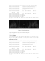
Figure 26: CPU at 20 Users ............................................................................................ 96
Figure 27: The CPU at 40 Users .................................................................................... 97
Figure 28: The CPU at 60 Users ................................................................................... 98
Figure 29: The CPU at 80 Users .................................................................................... 98
Figure 30: The CPU at 100 Users .................................................................................. 99
5
Acknowledgements
I would like to thank the Project Supervisor, Dr W.Buchanan for his guidance,
time and encouragement. Thanks also to Mr P. Duncan who kindly assisted with
the requirements analysis of the sample application.
6
1
Introduction
The enabling technology of the Internet is a very fast moving and exciting field.
New standards and technologies appear all the time, bringing together various
aspects of distributed computing and software engineering to provide the basis for
the Internet applications of tomorrow. This project takes a sample application and
examines how best it can be designed and implemented, in order to create a
modifiable application, suitable as a model for other similar systems
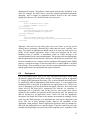
The sample application is an on-line restaurant table-booking system, which
attempts to provide some solution to the problems posed by randomly fluctuating
trade levels, by utilising up to the minute information. An interface in each
restaurant being used to record bookings as they happen, with customers using a
Web Site to request and book reservations. The application is given details of
concessions the restaurants are prepared to give during quiet trading times and
thresholds where these offers are either applied or withdrawn. Effectively using
supply and demand dynamics to encourage trade at quiet times. Additionally, if a
restaurant in the group is unable to accommodate a customers booking request
from the Web Site, the customer is informed of any other outlets that have
availability. An incentive to book at one of these restaurants may also be
displayed.
The sample application could be modified for use in many other areas such as
collecting data in real-time, performing some analysis and then presenting the
findings on the Internet. With this in mind, efforts have been made to ensure the
application could be modified to meet other needs with the minimum of change.
The system architecture and implementation have been specially selected to
support this goal, and thus present a system that could be used as a model to base
other similar applications on.
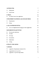
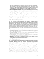
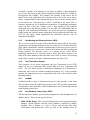
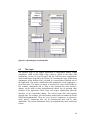
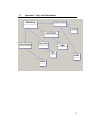
The diagram in Figure 1; A Basic Model of the System and Clients, is a model of
how the system interacts with the two client types.
7
Figure 1; A Basic Model of the System and Clients
8
1.1
Background
1.1.1
Similar Systems
Several on-line restaurant table-booking services operate on a regional basis in the
UK, mostly in London, with at least one nationwide service. 'In-by-5pm', is a
successful, nationwide service started by two restaurant owners from Glasgow. It
is based on the principle that many restaurants have a quiet period between 5pm
and 7pm most days. Restaurants may advertise a special offer on the Web Site
that customers can take advantage of, so long as they leave before 7pm. The
restaurants specify how many table places are initially available, and these are
decremented as customers book. A facsimile is sent to the restaurant with the
booking details. If a restaurant in the scheme decides that trade conditions are too
busy, they may either contact the service organisers by telephone to remove the
remaining table places, or use the Web Site to book them all up.
The sample application developed for this project is similar as it allows customers
to book restaurant tables on-line, and that special offers are used by restaurants in
an attempt to increase trade at quieter times. The real-time aspect of the system
developed here is a major difference between the two. The existing system has no
support for real-time bookings entered by the restaurants themselves. This is
provided here in order to enable the information displayed on the Web Site to
reflect the current trading levels.
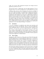
It is possible to view the sample application as two separate co-operating systems.
One managing bookings on behalf of the restaurant staff, while the other displays
special offers and manages bookings on behalf of customers via the Web Site.
Further, it is possible to use each of the systems without the other. The Web Site
could be used without support for real-time bookings, by simply leaving the staff
side of the application unused. The restaurants would then dedicate a static
amount of table places to the service without having to update the bookings made
by staff. Effectively implementing a system very similar to the existing service
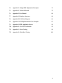
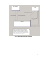
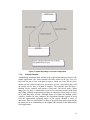
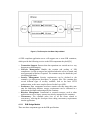
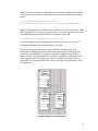
outlined previously. Figure 2; The System Using Only the Web Site, shows a
basic model of the system in this configuration. The sample application could
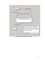
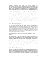
therefore be seen as extending the existing service. Note also that the Web Site
could be disabled instead, and thus the system operates as an in-house booking
application. This is illustrated in Figure 3; System Operating in a Closed
Configuration
9
Figure 2; The System Using Only the Web Site
10
Figure 3; System Operating in a Closed Configuration
1.1.2
Industry Partners
An Edinburgh restaurant chain assisted in the requirements gathering stages of the
sample application. The chain currently has three outlets in the city, two very
busy and one not so busy, with plans to open a fourth very soon. The two busy
outlets can use a table around six or seven times over on a typical busy day, with
an average service time of around 90 minutes. The company does not have a
booking service currently, and operate a 'first-come, first-served' policy. When
things get very busy, a whiteboard is used to list customers' names at the front
door along with their requirements and they are informed of how long it is likely
to be until their table is ready. Although unsure of whether the booking system
would be suitable for their company, the Operations Manager agreed to assist
with the requirements gathering stages of the project through a series of
interviews. This was most helpful, as many of the points that came to light during
the interviews were contradictory to the original ideas formed for the functionality
of the application.
11
1.2
Project Aims
The overall project objective is to present an application sufficiently well
designed and implemented that it could be used as a model for other such
applications. As such, the quality of modifiability is the primary quality required
from this project. Through this quality comes the ability to extend and adapt the
application to meet the needs of other similar systems.
Modifiability, as defined by Bass et al [1]:
The ability to make changes quickly and cost effectively
follows directly from the architecture. Modifiability is largely
the locality of any change. Making a widespread change to
the system is more costly than making a change to a single
component, all things considered.
It is also suggested that modifications fall into four broad categories:
Extending or changing capabilities. Adding new functionality, enhancing existing
functionality, or repairing bugs. The ability to acquire new features is called extensibility.
Deleting unwanted capabilities. To streamline or simplify the functionality of an existing
application.
Adapting to new operating environments. For example, processor hard-ware,
input/output devices and logical devices. This kind of modification occurs so often that
the quality of being amenable to it has a special name, portability. Portability makes a
product more flexible in how it can be fielded.
Restructuring. For example, rationalising system services, modularising, optimising, or
creating reusable components that may be used in other systems.
From these definitions it can be seen that the goal of modifiability implies that the
system must also be portable, defined as:
Portability is the ability of a system to run under different computing
environments. These environments can be hardware, software or a
combination of the two. A system is portable to the extent that all of the
assumptions about any particular computing environment are confined
to one component, or at worst a small number of easily changed
components.
If the sample application can meet at least some of the requirements detailed
above, it is hoped that the Project will have succeeded in presenting a generic
model, capable of forming the basis of other similar applications.
12
1.2.1
Summary
This section has given an outline of what the Project is about and a brief
description of the sample application that was developed during the Project. A
quick summary of similar systems was also provided, along with a comparison to
the sample application. A partner in Industry was identified along with the role
they played in the Project. This concludes the introduction, and the following
section looks at the theory and evolution of Web application architecture.
13
2
Theory
Before undertaking any design or implementation, a survey of relative
information was performed to investigate the subject area. The findings of this are
summarised in this section.
2.1
The Three Layers of an Application
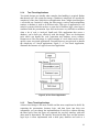
Most applications, whether they are Web based or not, have three logical layers.
•
•
•
Data layer. Manages the data used by the application. An application that
stores its data in data files is said to implement the data layer itself. Many
applications use a database to manage the storage of data. In these cases, the
database itself is considered to be the data layer of the application.
Business logic layer. Contains the various rules and operations that the
application performs on its data. For example, when an order is placed
through an e-commerce Web Site then the data layer stores the order details
while the business logic layer performs all the required calculations, validates
credit card numbers and ensures all the relevant information is present.
Presentation layer. Handles and displays the interface which enables the user
to interact with the system. Graphical User Interfaces (GUI) and Web pages
are typical examples of a presentation layer.
These three parts of the application are referred to as layers because they build on
each other. The data layer is the lowest level of the application and deals with the
management and storage of raw data. The business layer sits on top of the data
layer and ensures the data is processed according to the needs of the application.
The application layer sits on top of the business layer and makes the whole
application useful to the users.
2.1.1
Application Tiers
Applications can be categorised by the number of tiers they have. A tier is a
grouping of the three layers into a single component of the application. Although
there are only three sections (Data, Business Logic, and Presentation) there are
actually four categories for an application.
•
•
•
Single-tiered applications. All three sections combined into a single
component, which is usually an executable program. Many PC applications
fall into this category such as word processors and spreadsheets, and some
simple Web based applications.
Two-tiered applications. The data layer is separated out from the
presentation and business layers, while the latter are still combined. Although
it is possible to separate the presentation layer and leave the business logic
and data layers combined, this is not usual as most applications, which
separate the presentation layer, will also separate the remaining two as well.
Three-tiered applications. Separate the three layers into separate
14
•
components. These applications typically use distributed middleware to allow
disjoint components of the system to communicate and work together.
N-tiered applications. Similar to three tiered applications, but more
distributed. An N-tiered application has many distributed objects spread
across many machines, again using middleware. These objects may have their
own individual, separate data layers.
2.1.2
The Evolution of Applications
Over the last forty years, applications have evolved from the single tiered
application running on a mainframe computer to the highly distributed N-tiered
systems used today. Databases became popular in the 1970s and became very
widely used in the 1980s when the PC emerged along with the local area network.
The single-tiered applications began to separate into two-tiered applications with
the database handling in the data layer. From here, applications began to make the
use of remote procedure calls (RPC), in which a client calls a procedure on a
server. The layers in applications could then become more separated into the
tiered layers used in many systems today.
2.1.3
Single-Tiered Applications
Many small Web applications are single-tiered and operate very effectively. There
are many situations where this design is appropriate. Not all systems require a
complex separation of layers, and in some cases to do so would be a waste of
effort. Many small applications can be built using this design. On-line surveys or
message boards are suited to this style of application. Figure 4; The Single-Tiered
Architecture, shows the single-tiered architecture.
Figure 4; The Single-Tiered Architecture
15
2.1.4
Two-Tiered Applications
Two-tiered designs are suitable when complex data handling is required. Rather
than directly use a file system for storage, a database is employed. It is usually the
complexity of the data, which drives an application from a single-tiered design to
a two-tiered one. Instead of coding the data storage, retrieval and manipulation
routines, a database is used to do all these tasks. This type of application is well
suited to systems which do not have a great deal of business logic, since logic is
combined with the presentation layer and can become very difficult to maintain
when a lot of code is involved. Small-scale Web applications that access a
database, can be built very effectively with this design. There are development
tools which can handle the code generation and database access routines,
Dreamweaver Ultra Developer is a good example of a tool which can be used to
quickly create two-tiered applications. Presently there are no such tools to handle
the complexity of 3-tiered applications. Figure 5; A Two-Tiered Application,
illustrates the structure of a typical two-tiered application.
Figure 5; A Two-Tiered Application
2.1.5
Three-Tiered Applications
A three-tiered design is the most flexible and the most complicated to build. By
separating the presentation, business logic, and data layers into their own
components, you can change the implementation of each layer without affecting
the other layers. Since the layers are separated, the way they interface with each
other must be determined. The interface between the data layer and the business
logic layer is often implemented with a third party database tool such as a
16
database driver or object to relational mapping tool. The interface between the
business logic layer and the presentation layer is often the most difficult part to
design, especially in Web based applications. In a traditional three-tiered
application with a GUI, the coupling between the business logic and presentation
layers is quite tight. This enables the interface to respond immediately to user
requests and can perform more frequent interactions. In a Web application, the
coupling is looser and the interaction between the user and server is much slower.
For example, most data entry systems must validate that the data is formatted
correctly before committing it to the database, to prevent various data problems.
In a typical GUI system the data can be checked immediately and instant
feedback given, whereas with a Web application the user must submit the data to
the server and await validation, making the process much slower. JavaScript
routines can be used to help the situation somewhat, but not all browsers can
process JavaScript and some have scripting disabled. Figure 6; The Three-Tiered
Architecture illustrates the structure of this architecture.
Figure 6; The Three-Tiered Architecture
2.1.6
Application Architecture Design Decisions
Several factors affect which architecture should be used for a project and these
must be evaluated before a decision is made. The most prominent is the
complexity of the application, the more complex then the more tiers it is likely to
require. By portioning the application into multiple tiers, it becomes easier to
17
manage complexity since each layer can be treated as an individual component
with defined interfaces. This ensures that changes can be made to each of the
layers implementation without impacting on the others, so long as the interface
contract remains unchanged. This brings the benefits of maintainability and
extensibility and is suited to large production scale developments. However,
although separating the application into tiers helps to reduce complexity in the
longer term, the initial development overheads are much higher. Middleware must
be used in most cases to allow individual components to communicate, which is a
complex technology in itself. Added to the expertise required to create
component-based software, projects involving more than two-tiers can become
time consuming and expensive. Two-tiered architectures on the other hand can be
generated almost automatically using Computer Aided Software Engineering
tools (CASE). These are particularly suited to developments, which either do not
have complex business logic requirements, or are unlikely to be used for a long
period of time. Since the mixture of business logic and presentation code make
them very difficult to maintain and extend. A typical example of good use of a
two-tiered architecture would be a transitional system, used while a legacy system
was upgraded. Skill is another factor, which can affect the architecture decision.
The less skill available to a development team, then the capability to build more
tiers diminishes [2].
2.1.7
Hybrid Architectures
The entire application need not share the same architecture. Many applications
can be built using a mixture of two-tiered and three-tiered designs. A typical
example would be an application utilising the three-tiered architecture for the
mainstay of its functionality, while providing in-house database administration
services through a two-tiered design. To use a three-tiered design for the in-house
facilities may be considered excessive. Likewise, an application could be built
mainly around the two-tiered model but use a form of the three-tiered model to
access some remote service or data.
2.1.8
The Evolution of Web Applications
In order to understand the way Web applications have developed to date, it is
useful to examine the problems particular to Web based applications, and to see
how these have been solved historically. Web applications are different from
ordinary applications and the following issues are of particular relevance.
•
•
Open Model Systems. Theoretically there is no limit to the amount of clients
as opposed to a Closed Model System operating on a local area network with
a determinable number of clients. This means scalability is a very big issue if
an application is to more than a simple system with only a few expected users.
Stateless Protocol. The Hyper Text Transmission Protocol (HTTP) is used to
communicate between client and server. It is stateless protocol, which does
not support conversational state between the client and the server. When a
browser requests a page from the Web server, it opens a connection, retrieves
18
•
•
the page and then closes the connection. Since no connection is maintained,
the server has no idea what is happening on the browser. The browser could
crash or the entire client computer could be turned off, and the server would
remain oblivious. Session handling has to be built into the application code.
Ever Changing Environment. Much of the work of Web based applications
is in providing dynamic data on rapidly changing sites, which requires careful
architectural planning and management.
Security. Support for security and transactions are required in order to
provide on-line purchases. The Internet is a public network and that makes
authorisation, authentication and encryption critical.
Web applications have gone through three distinct generations during their
evolution. A short description of these follows.
2.1.9
Common Gateway Interface
The first generation of Web applications were based on Common Gateway
Interface (CGI) technology; these applications are independent systems, originally
developed for Unix platforms. They are invoked by Web servers with CGI
providing the gateway between the Web and the existing applications. Although
somewhat primitive compared to technology available today, CGI is still at the
heart of many of the applications running on the Web. The languages Perl and C
shell are used for most of the CGI scripts. The main problems with this approach
are:
•
•
•
•
Scalability Problems. Unless a CGI application is designed to be very large it
can be very difficult to extend.
Session Handling. This must be built into the application, and CGI only
provides primitive runtime information from the server.
Maintainability. The maintenance and administration of the many scripts
used in a large application can become very difficult.
Efficiency. CGI operates by spawning an external program when a script is
called, and this has a substantial system overhead.
2.1.10
Proprietary Solutions
The second generation of Web applications was based on proprietary Application
Programmer Interfaces (API), for example, NetDynamics and Netscape
Application Server [3]. These tend to use dynamic link libraries, similar to those
used in Microsoft Windows programs. This made the service time much faster
since the Web server does not have to wait for another program to start up. The
downside to this is that should one of the libraries crash then the whole server
could easily crash, because the code routine is shared. The main drawback in this
type of application server is their proprietary nature, resulting in a lock-in to one
specific vendor. Also, as they use shared libraries, only a limited number of
languages can be used to create the library. Both first and second-generation
application servers lack support for possibly the most important functionality
required of a Web application - transactional support. Any Web based commercial
19
operation involves a transaction in some form. Credit card authorisation, data
retrieval and storage all must be treated as transactions to ensure the integrity of
the application. Many single transactions must be combined to form aggregate
transactions, where if one fails they all fail. An example would be purchasing a
book with a credit card on-line. If the write transaction fails when the order is
committed to the database after the credit card transaction completes, then the
credit card transaction must be rolled back because the sale has not actually been
completed.
2.1.11
Application Servers
The third generation of Web application server supports a multi-tiered
architecture, and is made from multiple components. Applications that run in
these severs typically have separate parts for client/GUI, business logic, and
database/persistence layer. In its most basic form a third generation application
server can be viewed as middleware, holding together the various component
parts that make up the applications it contains. This type of application server
typically supports multiple client types. They may be Internet Browsers, Javabased programs, or other Web-enabled programming environments running on the
first tier. These constitute the presentation layer. The second tier is the
middleware, the application server and hosts a combination of presentation and
business logic components. The third tier is a combination of existing applications
and data stores, such as legacy systems and relational databases.
Third generation Web application servers include Distributed interNet
Applications Architecture (DNA) and forthcoming .NET architectures from
Microsoft, CORBA servers, WebObjects from Apple, Weblogic from Bea
Systems, and WebSphere from IBM [4]. They are distinguished by the API that is
supported by them, of which there are two prominent types, the proprietary DNA
system from Microsoft and the open standard, Java 2 Enterprise Edition API that
is the result of a collaboration led my Sun Microsystems and includes IBM, BEA
Systems and the Oracle Corporation [5].
2.1.12
Microsoft Windows Distributed interNeT Applications Architecture
(DNA)
This was designed to simplify the complex problems associated with the
development, deployment and management of multi-tier applications. It has
evolved from the middleware services provided in Windows NT, such as the
Component Object Model (COM), Distributed Component Object Model
(DCOM), Microsoft Transaction Server (MTS), and Microsoft Message Queue
(MSMQ). The mainstay of the Windows DNA is COM+, which is a language
independent standard for building reusable components and includes several
middleware services such as transaction management, resource management and
security management [6]. The object model of Windows DNA is shown in Figure
7; The Windows DNA Object Model.
20
Figure 7; The Windows DNA Object Model
The presentation tier of Windows DNA can include CORBA clients using a
COM-CORBA bridge, ActiveX Controls running within a Web browser,
standalone applications, Internet Server API (ISAPI) programs, Active Server
Pages (ASP), and static Web pages. Clients use Microsoft's Active Directory to
locate middle tier components, and use DCOM to invoke methods on those
components. Messages may also be sent asynchronously using Microsoft
Messaging Service (MSMQ), COM+ events or queued component technology.
The business tier contains business and data logic encapsulated within COM+
components, which can be written in any language, which supports COM+. All
invocations to COM+ components are intercepted by the COM+ runtime and
delegated to the components. Thus giving COM+ runtime the opportunity to
perform middleware operations, such as transactions, security and object lifecycle
management. The data layer of the architecture is served by Active Database
Objects (ADO) along with Open Database Connectivity. An integration server
called Babylon from Microsoft provides connectivity to existing legacy systems
via proprietary protocols.
21
2.1.13
Java 2 Platform Enterprise Edition (J2EE)
J2EE also was created with the goal of simplifying complex multi-tiered
distributed applications. It is an open standard, which was set out by Sun
Microsystems as part of the development of a previous set of standards known as
Java Platform for Enterprise (JPE), which included Enterprise Java Beans (EJB),
Java Servlets, and the Java Naming and Directory Interface (JNDI) [7]. The goal
of both JPE and J2EE was to create a set of standards, which would allow any
middleware vendor to implement an execution environment for distributed
enterprise applications. The JPE standard faced problems with no way to test if a
vendors implementation actually met the JPE specifications, however this
problem has been addressed in the J2EE specification [8]. Vendors must
implement a specific underlying platform in order to meet the J2EE standard,
which has created a standard platform for running these types of applications.
There are over twenty-five different vendors of J2EE compliant application
servers, including IBM, Oracle Corporation and BAE Systems [9].
The presentation tier of a typical J2EE system may contain CORBA clients, Java
applets, Java applications, Java Servlets, JavaServer Pages (JSP), and static Web
pages. CORBA clients use the CORBA naming service (COSNaming) to locate
middle tier components [10], while Java clients use JNDI. These clients invoke
methods on the middle tier components using CORBA/IIOP and RMI-IIOP
respectively. Messages may also be sent asynchronously using the Java
Messaging Service (JMS) [11]. The middle tier contains components that conform
to the EJB specification and like COM+ components they are used to encapsulate
business and data logic. Similarly, when the EJB container receives a call to one
of these components, it is intercepted and delegated to the component by the
container. At the point of interception, the container is able to perform the
required middleware tasks, such as transactions, security, or persistence. The data
layer utilises either Java Database Connectivity (JDBC) or SQL/J, which can be
used to interlace Java code with Structured Query Language (SQL) [12].
Integration with existing systems is performed using proprietary means. The
object model of J2EE is shown in Figure 8; The J2EE Object Model.
22
Figure 8; The J2EE Object Model
2.1.14
Server Side Components
The business logic of both architectures is handled by server side software
components, which reside in the middle tier of the application and are managed
by the application server. These components have well defined interfaces that are
declared to the container which manages them. They are also listed in a directory
to enable clients to look them up and bind to. It is these components which create
the functionality of the application, since they handle most of the applications
semantics. The data layer and the presentation layer are best left to manage data
and control the user interface specific tasks. There are two main types of these
components, data oriented and session oriented, with the latter sub-divided into
stateful and stateless types. Session oriented components will be invoked to
handle one particular clients request, and typically contain only business logic.
23
They have a one to one relationship with the client that called them, and are
destroyed or returned to the pool of waiting components as soon as a clients
session is terminated. An example of such a component would be that of a tax
calculation component, used to return the tax on an order. The component is
called as required, supplied parameters or asked to obtain information from other
components, then returns a value to its client. No state is maintained by these
components and they are termed stateless business components. Stateful business
components are supported by both J2EE and DNA [13]. Typically, these hold
non-persistent data for the lifetime of a clients session. A common example is a
shopping cart used to store a customers order while they browse an on-line store.
Data components are used to represent data in the underlying storage facility and
form an object view of a database tuple. Typical examples could include credit
card numbers, or employee personnel records.
Although DNA and J2EE architectures are quite similar, they way they handle
data components is significantly different. In a J2EE system, the container, which
holds the components, can handle the persistence of data components. This means
that the container can be instructed about which database schema to use, and
trusted to handle the storage and retrieval of the data components. This is known
as declarative persistence, since the requirements are declared to the application
server rather than programmed into the components themselves. DNA does not
support declarative persistence and has no automated persistence support [14].
There is no data component type in COM+ and all component persistence is done
programmatically through Active Data Objects (ADO) and OLE DB [15]. This
makes the creation of systems somewhat more difficult, since data components
are a more natural abstraction. It is much easier to use a method call
'employee.getPassword()', than it is to manipulate a relational result set. A good
example of how useful data components can be, is that of changing the underlying
schema in a large application. Because the data components abstract the
underlying database schema from the code, there is little or no change required in
the business component code. This is because the business components only
interact with the data components, and never with the underlying database.
Without this abstraction, changing just a few column names in the underlying
database schema would typically involve changing hundreds or even thousands of
lines of code [16].
2.1.15
Summary
This section began by describing the types of application architecture that Web
based systems are commonly built around. The evolution of Web application
architectures was then summarised, with a particular focus the third generation,
component based architectures. The two most prominent component architectures
were then given a brief comparison, and the 2JEE model was identified as
supporting declarative component persistence, not supported by the DNA model.
The following section leaves implementation specific details, and deals with the
requirements gathering and analysis stages of the Project. The aims of the next
24
section are to understand and analyse the functionality required of the sample
application, without considering the final implementation.
25
3
Requirements Gathering, Analysis and
Design
3.1
Requirements
The first step in this process was to take a set of draft proposals to the Operations
Manager and informally discuss the viability of these. This interview covered all
aspects of the proposed system and possible ways to proceed. The important
points are listed below.
•
•
•
•
Specific Tables. In the initial concept for the application, it was thought that
customers would be able to choose their own tables via the Web Site, however
it was soon found out that, for this chain of restaurants at least, that this would
not viable. Tables in the restaurants are not fixed in position, and are often
rearranged to suit the needs of large groups of people. To accommodate this
would require a feature that enabled the staff to model the exact layout of the
restaurant after moving tables. Although this would be possible, it is unlikely
the staff would have time for this extra task during peak times. So, this idea
was dropped from the specification and a system that indicated remaining
capacity in table places was adopted instead.
Control. The Operations Manager expressed concern that the staff must be
able to disable the booking facility at any time, as during peak times there
may not be any trained staff available to operate the system. Therefore, a
facility that could disable the Web booking service was to be included. In
addition, a service that could disable the special offers was required, if for any
reason the management decided that it was not required to offer a concession,
but still wanted to accept on-line bookings.
Speed. Since two of the outlets experienced very heavy trade at times, a
system that would allow staff to record bookings very quickly was needed.
Although under normal conditions it would be desirable to record the
customers details, at busy times a 'speed booking' option was required.
Alternatives. In addition to offering customers concessions at quiet times, it
was noticed that the system would be able to suggest alternative bookings at
other outlets if their original choice was unavailable. A feature that would
present the customer with a list of alternatives, alongside some incentive to
book there, was included in the specification.
An interesting point about security was raised by the Project Supervisor at one of
the project meetings. It would be possible for an individual to abuse the system
and book up all the tables, unless some form of security was built in to the Web
Site. Without protection against this type of abuse, the system would pose a risk
to the organisation. Methods to combat this were considered and added to the
specification.
26
Use Cases
From the initial interview, a fair picture of the systems requirements was being
built up. To specify and validate these, a technique known as Jacobsons Use
Cases, was employed [17]. This technique defines a system from a users
standpoint, using actions and reactions. One of the strengths of this way of
modeling a system is that users can easily understand the model. This was used to
validate the initial model with the Operations Manager before continuing with any
more analysis. Following the validation of these initial use cases, a more concrete
requirements analysis was created and is available in Appendix A: Requirements
Analysis. The actual use cases developed can be found in Appendix B: Use Cases.
A language independent model of the system was created from the use cases. This
can be found in Appendix C: Top Level Object Model
3.2
Design
Taking the use cases and object model as input , this stage of the process was
concerned with how best to meet the needs of the restaurant booking system,
while keeping in mind the Projects overall aims and objective.
3.2.1
Architecture
The starting point for creating the design was to look at architectures that could be
employed. Selecting a suitable architecture would enable similar systems to be
based around the design choices made here. As the architecture of a system is
very much a reusable attribute, with choices and decisions made being reused in
subsequent systems. To select the correct architecture for the system, the desired
quality attributes must be defined. These are summarised below.
•
•
•
•
Performance. In order to be a useful system, the response time must be
within a time perceived by the user as acceptable. A common rule of thumb in
client server systems is a sub-second processing time [18], taking no account
of the network propagation time.
Availability. In use, the booking information for the restaurant chain would
be entrusted to the system. Therefore, high availability is a quality required, as
staff would have no way to view booking information without the system.
Without the correct booking information, staff would be unable to ensure
double bookings did not take place.
Modifiability. This quality was defined as the overall Project objective from
the very beginning of the Project.
Portability. Again, this is required in order to achieve the overall Project aims
and can be seen as a requirement to gain modifiability, as outlined in section
one.
In a Web based application, performance and availability are as dependant on the
supporting architecture and application model as they are on the implementation
27
itself. This is covered in detail in the following section. The modifiability and
portability qualities can be obtained through the layered architectural style. The
layered style assigns the components of the system to layers, in order to control
inter-component interaction. The lowest layer provides some core functionality
and each successive layer add some functionality, which other layers make use of.
It achieves the goals of modifiability and portability through the controlled
component interaction. If the system is to be ported to another platform, then only
the lowest layer will require re-implementation, thus achieving portability.
Likewise, if one layer is replaced, then only changes to its neighbors may be
necessary, increasing modifiability. However, the trade off here is performance,
as several layers of components will increase the amount of communication
required for an operation. This can be offset by layer bridging, where some layers
are missed out by communicating processes in order to gain performance.
However, this should be avoided as it negates the benefits sought by this style.
3.2.2
Clients
A choice had to be made at this stage as to which type of clients were to be used
by the staff in the restaurants. The customers would access the system by way of
internet browsers, although other means would be possible, the simplicity of an
HTML is very attractive. makes other options hardly worth considering. The staff
interface however could be created using either Fat Clients or Thin Clients. A Fat
Client is the term given to a programmatic client used to access a system. In this
model, the client used to access the system actually contains some processing and
business logic, which is executed on the client machine before reaching the
server. The decreased number of iterations the user must make to communicate
with the server speeds up the users perceived system response time. A small
performance increase can also be achieved since validation and some processing
may be done out with the main application. The downside to this model is
associated with the distribution of business logic and its maintenance. If business
logic is embedded into the client, then updating that logic can cause problems in
large systems. Care must be taken to ensure that every client has been updated
with the new business rules every time they change and some way of
automatically updating them is required in very large systems. An alternative to
this approach is the Thin Client model. This typically uses internet browsers and
HTML as the client interface. Since the HTML can be generated on demand by
the application, the need for updating many clients is avoided. The business logic
stays in a central location and can be administered with greater ease and control.
The trade off here is that the number of iterations between client and server can
increase since only limited validation can be performed on the client via scripting
languages available through the browser.
The decision to use Thin Clients was made, as this meets the modifiability aims of
the Project. In addition, by using Thin Clients that are created from HTML, new
interfaces can be created very quickly. This meets the goal of becoming a generic
model better than Fat Clients, as to create a GUI is a much more involved process.
Additionally, parts of the Thin Client interface can be generated automatically
28
based on attributes of the system. For example, HTML selection lists to allow the
user to choose which outlet to book at can be generated dynamically, based on the
outlets currently taking orders, this was deemed a very useful feature.
3.2.3
Data
A decision on the storage arrangements for the application data was required at
this stage. Although other forms of data storage exist, the two options considered
was a relational database or a series of text files. The abstraction provided by a
relational database is very useful. Platform issues are minimised with this
approach, as to code the application using text files creates dependencies on the
underlying operating system. Critical issues such as transactions can also be
provided by a relational database, so the decision to this approach was made.
Several database vendors provide free evaluations of their product, so one of these
was used.
3.2.4
Network Issues
The Internet provides the perfect medium for this system. The availability of
broadband connection through Asymmetric Digital Subscriber Line (ADSL) or
via optical cable allows the outlets to connect via a reasonably fast and stable
means. For prototyping purposes a standard 56k modem connection would
suffice, but if the system were to be fully implemented then broadband
connections would be required for the outlets.
3.2.5
Server Issues.
Two options were considered here. Use a third party to host the actual application,
or use a computer located in one of the outlets to run an application server. The
amount of control and flexibility offered by hosting the application in one of the
outlets makes this a better option. In addition, performance and availability issues
are easier to address by hosting the application server in-house. Again, many
application server vendors provide free evaluation periods for their products so
this option was selected.
3.2.6
Summary
This section of the Project concluded that the system would utilise the layered
architectural style, and use a relational database as the underlying data storage and
retrieval facility. Both the customer and staff clients were to be thin client HTML
based interfaces, connected to the application via the Internet, with broadband
connections for the outlets. The application server would ideally be located inhouse.
29
4
Java 2 Enterprise Edition
In the Theory Section, two component oriented, server architectures were
described, J2EE and Microsoft DNA. The declarative component persistence of
J2EE makes it an ideal choice for this project. By abstracting the database specific
details into a deployment descriptor, a high degree of portability is achieved. This
section outlines the J2EE technologies that are used in the Project in order to give
the reader some background information, before the implementation used for the
sample application is described in the next section.
4.1
Java as an Implementation Language for Web Applications
The Java programming language provides the following specifications that were
designed for use in Web based applications. They also form part of the J2EE
specification. There are many more aspects to the J2EE specification, but the only
the ones used for the Project have been listed.
4.1.1
Java Servlets
Similar to CGI in the way that they are precompiled code routines that reside on
the server and can be called into action from a Hyper Text Transfer Protocol
(HTTP) request. Servlets inherit behaviour from either the HTTPServlet or
GenericServlet classes as defined by Sun Microsystems. A servlet must
implement certain interfaces which are defined in their super-classes, such as
handling a HTTP request, sending a HTTP response, an initialisation routine and
a destroy routine. Generally the developer overrides these methods to create the
behavior required. Although servlets are typically used to send an HTML text
stream back to the browser, they may be configured to send a bit stream,
Extensible Markup Language (XML), or Wireless Markup Language (WML) as a
response. Since Java classes may be loaded at runtime, servlets do not require the
Web server to spawn an external process as in the case of CGI, making them more
efficient. When a servlet is loaded into the servers main memory, it will stay there
for a period of time, usually until the servlet container decides to call the destroy
method of the servlet. Until this time has passed, any more requests for the servlet
will generate a new thread of execution, rather than invoke another servlet. This
improves efficiency but can lead to problems when servlets are used to access
shared resources such as files, variables or database connections. When shared
resources are used with servlets it is important to employ thread safe
programming techniques. The use of synchronised method calls is a typical way
of dealing with shared resources. It basically locks a resource while it is being
used by one thread so the others cannot use it until it is released. It is possible to
declare whole servlets as thread safe, i.e. only one thread of execution at a time,
however this tends to slow down high volume applications as it creates a
bottleneck. Serlvets can instantiate other Java objects and can use all the Java
API's, which makes their potential use quite diverse.
30
4.1.2
Java Server Pages
These are actually a special case of servlet. When a JSP page is requested from
the Web server for the first time, the servlet engine compiles a servlet from the
Java code that is interlaced between the HTML on the page. This makes Web
pages which feature dynamic content much easier to design, as the page can be
manipulated using a Web page editor. Creating a Web page directly from a servlet
would be a very tedious task, with even minor changes to the Web page requiring
a programmer to alter and recompile the servlet source code. Using a JSP page to
combine the layout and dynamic requirements of the page allows for the
separation of design and code work. Although many of the Java APIs are
available to a JSP page, it is best to use a JSP page for only the most basic
presentation layer tasks in large applications. The reasons for this lie in the
complexity that can arise from mixing both HTML and Java code on the same
page, and performance issues in higher volume applications. However, for
presenting data that has been generated by other aspects of the application, they
are ideal, since changes to the template use to create the page layout will not
affect the code used to create the dynamic content. It is relatively simple to create
small Web applications that combine database access with JSP, and there is at
least one package available which enables the creation of dynamic Web pages
with only the need for a basic understanding of Java and relational databases. This
can be very useful for small applications or rapid prototyping. But unsuitable for
larger applications because of maintenance problems caused by the two-tiered
nature of the applications produced. It would be very difficult to maintain a large
application where the business logic code was inter-laced through with the
presentation code and HTML. As well as supporting normal Java syntax, JSP
support an alternative XML syntax that is designed for use with XML tools.
Custom JSP tags may be defined which allow parts of a Web applications
functionality to be included with small tags. These further separate the page
design process from the coding process, and allow Web page designers to insert
tags where certain functionality or content is required, with the tags defined by the
application programmers.
4.1.3
JavaBeans
These are Java classes that conform to a certain specification. JavaBeans have a
public constructor, which takes no arguments, declares its internal state as private
and will only allow access via get/set methods, and implements the Java
serializable interface. They can be manipulated using various visual design tools,
and are typically used in a Web application to encapsulate data and move it
around between components and objects.
4.1.4
Remote Method Invocation (RMI)
Similar to Remote Procedure Calls (RPC) in Unix systems, this technology allows
an object running on one computer, or Java Virtual Machine (JVM), to call a
method on an object residing on a different machine or JVM. This enables
distributed computing and is integrated tightly into the Java language. The RMI
architecture defines a proxy layer, which allows one object to perform a service
31
on behalf of another. The mapping of one object to another is done through the
use of stubs and skeletons and a special compiler included in the Java 2 Software
Development Kit (J2SDK). This compiler will generate a stub source file on
behalf of the client application, and a skeleton source file for the server object.
Object communication is done through this proxy layer over the network and so
far the objects are concerned, they could be operating in the same JVM. A
common requirement for all distributed architectures a marshalling mechanism
which can take a data type, change it into a form suitable for the transport
mechanism used, and then un-package it at the other side. RMI handles this by
using the Java serialization mechanism; any object that must be transported is
simply turned into a binary stream, transported, and de-serialized at the other side
[19]. So, any object, which implements the serializable interface, may be
transported using RMI.
4.1.5
Java Naming and Directory Service (JNDI)
This is a service, which is used to look up and bind to remote objects. It provides
an interface to all naming and directory services using Service Provider Interfaces
(SPI) which communicate with the existing naming or directory services such as
DNS. The naming service associates a name with an object and offers binding and
lookup methods. The directory service is a naming service, which allows
application attributes to be associated with a name; this allows objects to be
retrieved by their attributes rather than their name. JNDI is used by first looking
up the object, usually by its name, and then binding to the object [20].
4.1.6
Java Transaction Support
This comprises of two main components, the Java Transaction Service (JTS)
which is a low level transaction API, and the high level Java Transaction API
(JTA). The JTA allows groups of distributed components to be bound into a
transaction, and is used in container managed persistence [21]. As the container
manages the transaction services, requirements only have to be declared, rather
than programmed.
4.1.7
JavaMail
JavaMail provides a layer of abstraction on top of a mail provider, so the client
need not know about the underlying protocols used. This provides applications
with portable e-mail capabilities, since JavaMail takes care of interfacing with the
actual mailing system used.
4.1.8
Java Database Connectivity (JDBC)
This decouples the database type from the programmatic code through the use of
database drivers. There are four types of drivers:
•
JDBC-ODBC Bridge. This is used to bridge between Java applications and a
database, which complies with the Open Database Connectivity (ODBC)
standard. This is known as a Type 1 Driver and provides only basic
functionality and performance since all calls to the database must be
32
•
•
•
converted to ODBC compliant calls before execution [22].
Type 2 Drivers. These connect to the database through libraries, which
belong to the database, known as native libraries.
Type 3 Drivers. Placed between the client and the database and allow the
client to load pure Java classes, which can communicate directly with the
database management system.
Type 4 Drivers. Similar to Type 2 Drivers but use a proprietary protocol
instead of native libraries.
4.1.9
Enterprise Java Beans (EJB)
These are software components that execute on the application server, and are
used to provide business logic to their clients. Typically, they will reside in the
middle-tier of an application and can support standalone clients as well as browser
based clients. They encapsulate the business logic of an application, while leaving
tasks such as transaction management, concurrency, caching and security to the
EJB container(s) provided by the application server. In the case of container
managed persistence (CMP), storage and retrieval of data is also provided by the
EJB container. One of the main achievements of the EJB specification is that the
business logic development can be separated from the common tasks required in
all multi-tier developments, like concurrency, transactions, security and data
management. Since all these services are provided by the EJB container, the
application developers can concentrate on the application specific logic, with the
knowledge that the important underlying functionality is both already available
and well proven [23].
Although this type of functionality has been available from specifications like
CORBA previously, the EJB specification uses deployment descriptors to provide
portability between EJB compliant containers. The deployment descriptor in the
EJB 1.1 specification is comprised of an XML file that specifies exactly which
services are required from the container. This way a package of EJB components
can be created along with a deployment descriptor into any EJB container,
without any need for changes to the code. If a different database is used by the
container then only changes to the deployment descriptor need to be made.
4.1.10
The EJB Architecture
The diagram below illustrates the EJB object model.
33
Figure 9; The Enterprise JavaBean Object Model
A J2EE compliant application server will support one or more EJB containers,
which provide the following services to the EJB components they hold [24].
•
•
•
•
•
•
Transaction Support. Ensures that data operations are carried out in a way
that preserves data integrity.
Lifecycle Management. Handles the creation and pooling of EJB
components. A ready to run pool are initialised when the server is started, and
more generated in batches if required. The container may also shrink the pool
size during light loads.
Security Management. Security requirements can be declared to the
container via deployment descriptors, or property files. The container has
several different types of security available, such as the basic HTTP
authentication, or the more complex Secure Socket Layer (SSL).
Persistency. Data components need not contain code that maps their state
onto the underlying database, storage requirements can be indicated in a
deployment descriptor and managed by the container.
Resource Management. Connections to external resources, such as other
application servers or legacy systems may also be managed by the container.
Concurrency. The container takes care of all the issues related to
concurrency, relieving the developer from coding concurrency requirements
into the application.
4.1.11
EJB Design Models
There are three component types in the EJB specification.
34
•
•
•
Persistent. Called entity beans, they represent data that is stored in the
underlying data source. Typically, they will comprise of employee records,
booking information and other tuples from databases.
No State. Known as stateless session beans, these components do not store
any state on behalf of their clients so therefore may be shared between many
clients. They are relatively short lived and provide services such as
calculations.
Session Oriented. These components have a one-to-one relationship with
their clients and may store state. Their life is determined by the life of their
client. A typical example is a shopping cart on a Web Site.
Clients of an EJB will communicate through two interfaces, the home interface,
and the remote interface. The container will not allow a client to reference an EJB
directly. Thus, the EJB is isolated and the container can provide the services listed
above, since all calls to the EJB must go through the interfaces, which the
container intercepts.
Scalability and efficiency issues are addressed through this decoupling of the EJB
from its clients. If a client is long lived and uses an EJB component intermittently,
dedicating an EJB instance to the client would be wasteful. To get round this, the
client is allowed to bind to the interface of the EJB, and the container will allocate
instances of the EJB to calls made on the interface as required. This allows the
client what seems like a permanent bind to the EJB, but is in fact only a bind to
the interface, which will be matched to an instance of the EJB when it is required.
Thus, the container is free to manage the pool of available EJB instances to best
suit the servers load and availability requirements. If there are many simultaneous
client requests to a particular EJB, the container can pool instances of the EJB. If
the application needs more capacity on a permanent basis, then more hardware
resources can be allocated to the container, or several containers may be clustered
together to meet the requirements, without changing any of the application code.
The Home interface of an EJB is shared by all its clients and is concerned with
EJB lifecycle duties such as the creation and removal of the EJBs. Since an EJB
cannot be created in the usual way through its constructors, all of the methods for
creating a new EJB must be defined in its home interface. A home object is
generated from this interface automatically by the container. The remote interface
has no methods, but indicates to the container the methods of the EJB that may be
called from another JVM. This typically includes the business logic methods that
will be invoked on the EJB from its clients. An EJB object is automatically
generated from this interface and represents the clients view of the EJB. The EJB
does not actually implement the home and remote interfaces, although it must
provide corresponding method signatures as if it does. There is no one class that
corresponds to the EJB, rather it is a combination of the bean class provided by
the developer, and the classes generated by the container. The reason for this is to
allow the container to act as mediator between the client and EJB.
35
4.1.12
Summary
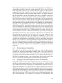
This section has given an overview of the technologies that were used to create
the sample application. Of particular importance is the EJB model, as it is through
this that the Project implements its core functionality. The EJB specification is a
very powerful combination of technologies, especially declarative component
persistence. The next section covers the implementation of the sample application
in detail, demonstrating how the features of the J2EE specification that were
described here can be put into practise.
36
5
Implementation and Testing
This section details the techniques and patterns implemented in the application.
More technically specific information can be found in the Technical Manual,
which gives information on maintaining and extending the system. A full class
diagram is also included in Appendix H: Full Class Diagram.
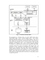
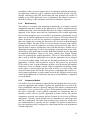
5.1
The Layered Architecture
The layered architectural style that was identified in the design stage has been
implemented using the structure detailed below.
Figure 10; Implementing the Layered Architecture
37
The underlying data source uses a relational database, which represents the data
layer. Access to data is provided only through the entity EJBs. These entity beans
provide an abstraction of the database and effectively convert the data tuples into
EJB component instances, and vice versa. The entity beans only communicate
directly with either the database (handled by the EJB container), or with the
session beans that make up the next layer of the application. No business logic
resides in the entity beans. The next layer up is implemented using session beans,
which contain the business logic required by the application. Generally these
session beans will provide services required of the application by looking up one
or more entity beans, performing some task using the data contained in the Beans,
and either return data to their client or ask an Entity Bean to change its state,
delete itself, or create a new Entity Bean. No access to the database is
implemented in the session beans. Servlets call the session beans and represent
another layer of the system. They are concerned with controlling the interface
interactions, and managing calls to the session beans. The actual presentation of
information is handled by a final layer comprised of HTML and JSP pages.
Through this arrangement, the layered architecture is implemented. Strict
communication rules have been implemented to ensure the architecture is pure. It
is possible to connect directly from a JSP page straight to an entity bean, or even
direct to the underlying data source, but this is known as layer bridging and
compromises the qualities of modifiability and portability. These are provided by
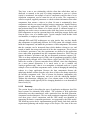
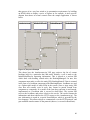
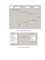
a pure layered architecture and represent the main Project objectives. The diagram
in Figure 11; The Communication Sequence, illustrates an abstraction of the
layered architecture communication sequence. Note that it is an abstraction and
only shows one session EJB communicating with one entity EJB, when in fact a
session EJB would typically communicate with several entity EJB components in
order to obtain data from several database tables. But the communication
sequence would remain the same as is shown here.
38
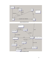
Figure 11; The Communication Sequence
This shows a typical interaction sequence. A page from the presentation layer
requests an HTTP response from one of the controller servlets. In order to process
the request, the servlet must lookup and call a method on one of the session EJBs.
It does this and in turn the session EJB must lookup and call methods on one ( or
more ) of the entity EJBs. Notice that when the call is made to the entity EJB, the
diagram shows container becoming involved. This is because a call made to an
EJB is always intercepted by the container and handled by the container. If this
were not so, the container could not provide transactional services, since it would
have no idea which EJBs were being called and when. By intercepting all calls,
the container is able to manage the resources needed by the EJBs. So it can be
seen that it is the container that actually retrieves the data on behalf of the entity
EJB on the diagram. The data is then returned to the session EJB, which performs
the required business logic processing on the data, and returns data to the
controller servlet. The servlet may then change the data to a form more suited to
its own client and then pass it on ( this can be useful where different client types
need access to the same application, a good example would be changing the data
for use by a mobile Internet device ). The client finally receives the data and may
39
then process it in a way best suited to its presentation requirements, by building
an HTML table to display a series of figures in for example. A more specific
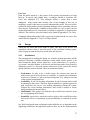
diagram that shows an actual scenario from the sample application is shown
below.
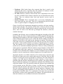
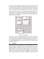
Figure 12; Sequence Example
This shows how the 'membersarea.jsp' JSP page retrieves the list of current
bookings held for a particular date and outlet. Initially, a call is made to the
InitialiseStaffServlet requesting information. This is passed to a session EJB
which deals with booking related tasks, the BookingManagerS. In turn, this
component must make a call to the entity EJB, BookingMasterE. Data is returned
in the form of a JavaBean component called BookingMaster. JavaBeans are used
as a 'lightweight' model of entity EJBs in the system. Since a singe entity EJB
class does not actually exist as such, they cannot be passed around from
component to component. So a model of the state they represent is used instead,
implemented as a JavaBean (this is covered in detail later). The session EJB
receives the JavaBean, and passes it back to the servlet. The servlet formats the
information and then redirects the HTTP request to the 'membersarea.jsp'. The
new information is stored in a special SessionObject, which is proveded by the
Java language. This allows objects to communicate over the HTTP protocol, and
gets round the stateless nature of the protocol (this too, is covered in detail later).
40
It can be seen from the preceding paragraphs that a considerable amount of effort
is required in order to maintain the strict inter-layer communication protocols that
the layered architecture provides. It would be much easier to allow the JSP pages
direct access to the entity EJBs, or even to the database itself. But to do so would
remove the portability and maintainability that the application currently has
achieved. Only two occurrences of layer bridging have been permitted in the
sample application. This was done to provide a basic administration facility to the
system, for use in development and deployment of the application. This is
illustrated below in the diagram, extracted from the application class diagram in
Appendix H: Full Class Diagram
Figure 13; Layer Bridging
Here the servlet at the foot of the diagram can be seen with a direct association to
the remote interface of the entity EJB, OfferMasterE. This allows it to make calls
directly to the EJB (via the EJB container) and obtain data from the database. This
was useful during development as a layered implementation for this type of
development based functionality seems excessive, but was not used for any other
areas of the application.
5.2
The Data
Customers and bookings are represented by corresponding database tables in a
schema dedicated to the application in the underlying database. An entity
relationship diagram and the SQL commands used to create the tables can be
found in Appendix G: Database Structure. Special offers are also stored a
database table, as are details on the Outlets themselves. This enables the
application to be altered and extended without changing any of the code. Rather
than hard code the amount of outlets into the application, the application will
search for outlet entity beans and use these. Consider the scenario in Figure 14;
41
Displaying Available Outlets, where the client wants to know which outlets are
currently in the system. The communication sequence is followed as defined
earlier and a list of the available outlets is returned from the data layer. The actual
database tables that are used to store the details of the outlets and offers are shown
in Figure 15; Outlet and Offer Tables. The information in these tables is passed
back to the presentation layer, and can then be used as required. The sample
application actually uses this data to create parts of the user interface dynamically.
The select list that is used to indicate which outlet the user wishes to book at is
populated with data in this way. Figure 16; Dynamic User Interface Element,
shows the select list already populated with some outlets. This select list is
generated by one of the servlets, based on the information held in the database.
This allows the system to be expanded with great ease, in fact an outlet could be
added to the application without even restarting the application server. Likewise,
special offers may be changed, removed or added while the application is running.
More details on this functionality are given in the technical manual, as are specific
details on the actual database tables. Without this function, every time outlets and
offers were changed, elements of the user interface code would require changes
also. By using dynamically generated HTML elements, based on the underlying
database, a high degree of modifiability is introduced. An example of the code
used to create a select list used to show an outlets booking status is given below,
this would typically reside in a servlet with the finished select list placed into the
session object for use by a JSP. Note that much of the code has been omitted for
clarity, only the most relevant lines are shown. The object 'outletMaster' has
already been populated with the state from an outlet EJB, and it is queried for its
booking status. The 'if' statement then ensures that the select list with the correct
value initially selected is created, note the word 'selected' in bold. It is created as a
string of characters that can be recognised as an HTML select list by an internet
browser. This string is then placed in the session object for use by a JSP page.
String bookingStatus = "";
int ou_booking_status = outletMaster.getOu_booking_status();
if(!ou_booking_status){
bookingStatus =
"<select
name='bookingstatus'onChange='document.forms[1].submit()'>
<option value='1'>on line booking enabled</option>
<option value='0' selected>on line booking
disabled</option></select>";
}else
bookingStatus =
"<select
name='bookingstatus'onChange='document.forms[1].submit()'>
<option value='1'selected>on line booking enabled</option>
<option value='0'>on line booking
disabled</option></select>";
}
session.setAttribute("bk_status",bookingStatus);
42
Figure 14; Displaying Available Outlets
Figure 15; Outlet and Offer Tables
43
<select name='bk_outlet'
onChange='document.forms[0].submit()'>
<option value='1'selected>grassmarket</option>
<option value='2'>cannonmills</option>
<option value='3'>broughton st </option>
</select>
Figure 16; Dynamic User Interface Element
5.2.1
Transactional Data
The EJB container makes sure that operations regarding the data are carried out in
a transactional way. A transaction could be defined as an operation or set of
operations that must be completed in full, or rolled back to the state the system
was in before hand. This safeguards against data integrity problems. To make use
of the transaction support provided by the EJB container, requirements for each
EJB must be declared in a deployment descriptor. This informs the container
about the type of support that is required for the beans, since different levels of
support are possible. The level of support required by the EJBs in the sample
application is termed 'required' and indicates to the container that a transaction
must be started before the bean is used. An extract from one of the deployment
descriptors is shown below, with the transaction details in bold.
<ejb-name>OfferSBean</ejb-name>
<home>prototype_a.OfferSHome</home>
<remote>prototype_a.OfferS</remote>
<ejb-class>prototype_a.OfferSBean</ejb-class>
<session-type>Stateful</session-type>
<transaction-type>Container</transaction-type></session>
<entity>
5.2.2
Entity EJBs
All of the data that is stored in the database must be accessed via entity EJB
components. These provide an object model of the data and have methods and
finder mechanisms that can be used by other components. Each has a home
interface, a remote interface, an implementation class and a primary key class. A
class diagram of an entity EJB component used in the sample application is given
in Figure 21; Class Diagram of an Entity EJB. It shows the four classes that are
used to make up the bean. The solid lines with arrows indicate associations with
other components, since the diagram has been extracted from the main class
diagram in Appendix H: Full Class Diagram, these are to be ignored here as they
are not relevant to this discussion. The dotted line that connects the remote
interface 'OutletMasterE', to the bean implementation class,'OutletMasterEBean'
is of interest. It denotes dependency, and illustrates that the remote interface is
tightly coupled to the EJB implementation class. A description of the four classes
is given below.
44
Remote Interface. This is known as a placeholder interface, that is, it has no
methods (only method signatures), but signals to the compiler that the class may
be called from a remote virtual machine. It lists the methods of the EJB
implementation class that a client may call. The code snippet in Figure 17; EJB
Remote Interface Code, shows the remote interface of the EJB in Figure 21; Class
Diagram of an Entity EJB. It defines four methods that may be called on the bean,
'noBookings', 'startBookings()', 'noOffers' and 'startOffers'. These methods will
initiate a transformation of the data represented by the bean. The 'noBookings'
method for example, will change the booking status of the outlet represented by
the bean to a false state, indicating that the outlet is no longer accepting bookings.
package prototype_a;
import javax.ejb.EJBObject;
import java.rmi.RemoteException;
import javax.ejb.EJBException;
public interface OutletMasterE extends EJBObject {
OutletMaster getOutletMaster() throws RemoteException,
EJBException;
void
void
void
void
noBookings() throws RemoteException, EJBException;
startBookings() throws RemoteException, EJBException;
noOffers() throws RemoteException, EJBException;
startOffers() throws RemoteException, EJBException;
/** @link dependency */
/*#OutletMasterEBean lnkEntity1Bean;*/
}
Figure 17; EJB Remote Interface Code Example
The Home Interface. This contains methods for creating new instances of the
bean and for locating existing instances. It must contain an 'ejbCreate' method that
has the same signature as the 'ejbCreate' method in the bean implementation class.
This method is required because an EJB cannot be instantiated in the normal way
, by use of a constructor. An example of the home interface of the
'OutletMasterEBean' is shown in Figure 18; EJB Home Interface Code Example.
This example only shows the 'ejbCreate' method, however the home interface of
an EJB may also contain what are known as finder methods, which are used by
the container to locate beans that contain certain attributes. The functionality they
provide is similar to SQL queries made on a relational database. For example, a
finder method could be set up to return a collection of 'outlet' beans that have their
booking attribute set to true, or to return a customer bean that matches a certain
surname. This is central to the declarative component persistence facility provided
by the container. Rather than program finder methods directly into the EJB
component, they are declared to the container via the deployment descriptor.
Finder methods only have method signatures in the home interface of the bean, no
matching signature or implementation is required in the beans implementation
class, since all the process of finding the beans is handled by the EJB container. A
45
special language is used in the deployment descriptor to define the finder
methods. The EJB 1.1 specification does not include a standardised language for
this, so at the moment the language used is specific to the vendor that supplies the
application server. A standardised container finder language is part of the
forthcoming EJB 2.0 standard and is XML based [25]. An example of the
Weblogic Query Language, as used in the sample application is shown in Figure
19; EJB Finder Method Language Example. The finder query here states that if
the 'bk_outlet' attribute of the bean matches the parameter supplied ($0), then the
expression equates to true.
package prototype_a;
import
import
import
import
javax.ejb.EJBHome;
javax.ejb.CreateException;
javax.ejb.EJBException;
java.rmi.RemoteException;
public interface OutletManagerSHome extends EJBHome {
OutletManagerS create() throws CreateException, EJBException,
RemoteException;
/** @link dependency */
/*#OutletManagerSBean lnkSession1Bean;*/
}
Figure 18; EJB Home Interface Code Example
<finder-list>
<finder>
<method-name>findByOutlet</method-name>
<method-params>
<method-param>long</method-param></method-params>
<finder-query><![CDATA[( = bk_outlet $0 )]]></finderquery></finder>
<finder>
Figure 19; EJB Finder Method Language Example
•
The Bean Implementation Class. This class contains the actual access
methods and implementation required of the bean. There are several methods
signatures that an EJB implementation class must contain, as these are called
by the container at certain times. For example, an EJB must have an
'ejbRemove', method signature. This is called by the container every time the
bean is destroyed and can be used to include any routines that need to be run
at this time. An example of an EJB implementation class is given in Appendix
I : EJB Implementation Class Example, note that all the required method
signatures have been indicated in bold. Other methods can be added to the
EJB that can be made available to its clients through the remote interface. In
the example, there is a method called 'getOutletMaster', indicated by bold and
46
italicised, that returns a JavaBean containing a copy of all the state held by the
EJB.
•
The Primary Key Class. Each entity bean must feature a unique primary key
attribute, to allow the container to store and retrieve the data it represents on a
relational database. In addition, the bean must also provide a mechanism by
where two primary keys may be compared for equality. That is the purpose of
the Primary Key Class. It implements a method named 'equals', which takes in
an object and compares it against the key held by the bean that it is associated
with, returning either true or false. The code in Figure 20; Entity Bean
Primary Key Code, shows an example of this class.
package prototype_a;
import java.io.Serializable;
public class OutletMasterEPK implements Serializable {
// this is the primary key
public long ou_number;
public int hashCode() {
return (int)this.ou_number;
}
public boolean equals(Object obj) {
if(obj instanceof OutletMasterEPK){
OutletMasterEPK otherKey = (OutletMasterEPK) obj;
return((this.ou_number == otherKey.ou_number));
}else
return false;
}
}
Figure 20; Entity Bean Primary Key Code
47
Figure 21; Class Diagram of an Entity EJB
5.3
The Logic
The business logic of the sample application is encapsulated entirely within
components called session EJBs. Logic could be placed in the entity EJB
components, servlets, or even JSP pages. But this would not have supported the
layered architecture required by the Project. By containing the logic within these
components, all the business logic is located in a central and well defined area of
the application. This makes modification and maintenance of the application a
great deal easier. The impact of change is lessened also, since session EJBs are
true software components and so long as they maintain the same interface,
changes can be made to their implementation without fear of upsetting other
elements of the application. Their clients only require modification when the
interfaces of the components change. The session beans deal with logically
grouped tasks. For example, all of the booking related tasks are handled by a bean
called 'BookingManagerS'. These are course grained components, as opposed to
small, generic components that can be parameterised and used in other
applications. The reasons behind this choice are explained fully in the conclusion
section.
48
5.3.1
Session EJBs
These differ in several ways from the entity EJBs described previously. Firstly,
they do not interact directly with the database, they use the interfaces of the entity
EJBs for data related operations. Secondly, they have a one-to-one relationship
with their clients, unlike entity EJBs who may have more than one client per bean.
Typically, one session bean is allocated by the container to service a clients
request. The bean and client have a one-to-one relationship for the time it takes to
run the method called by the client. Entity beans may have more than one client,
but the clients will be lined up awaiting service, the client at the front of the queue
accessing the bean, with the rest are queued up behind. Entity beans only provide
client access through their remote interface, whereas session beans provide access
via both home and remote interfaces. This is to ensure the transactional safety of
the entity bean, as many clients can call on the remote interface but the container
maintains the instances of the bean, in order to ensure transactional safety of the
data represented. This is not required of session beans since they are not
representing data that must be processed in a transactional manner, so the
container can allow access through both interfaces. Figure 22; Diagram of a
Session Bean, shows a class diagram of a session bean from the sample
application. Note how there are dependencies drawn between both interfaces and
the bean implementation class, instead of only one between the remote interface
and the implementation class as shown in Figure 21; Class Diagram of an Entity
EJB.
Example of Using A Session Bean.
The clients of the session beans in the sample application are all servlets. The
following example demonstrates the process a servlet uses to bind to and request
services from a session bean.
Step 1. The EJB must first be located via the JNDI naming context (for a
description of JNDI see the previous section). No parameters are required in the
method call as the EJB resides in the same server that the servlet is running in.
Context ctx = Util.getInitialContext();
Note that a class called 'Util', is used here. This is simply a utility class written to
abstract the server specific details of obtaining a reference to the JNDI context.
The actual method of this class is show below.
public static Context getInitialContext(String url) throws
Exception {
Properties p = new Properties();
p.put(Context.INITIAL_CONTEXT_FACTORY,
"Weblogic.jndi.WLInitialContextFactory");
p.put(Context.PROVIDER_URL, url);
return new InitialContext(p);
}
49
Step 2. Now that a reference to the JNDI context has been obtained, it can be used
to look up the home interface of the EJB required (enclosed within the quotation
marks).
OutletManagerSHome outletManagerSHome =
(OutletManagerSHome)ctx.lookup("prototype_a.OutletManagerSHome");
Step 3. Assuming that the EJB has been installed into the server with a JNDI
name matching the one in the quotation marks, the above operation will have
succeeded and a bind can then be made to an instance of the EJB.
outletManagerS = outletManagerSHome.create();
Now that a handle on the EJB has been created, the servlet is free to use any of
the methods defined in the remote interface of the EJB.
Note that only servlet clients have been covered here, but one of the great
advantages of building applications with EJBs is that different client types can
access the same methods. For example, a standalone application would use a
similar process to that described above to use the same EJBs as the servlets. This
allows applications to be written once and serve multiple client types. The core
application is written using EJBs, and various client types may all share the same
core application.
Figure 22; Diagram of a Session Bean
50
5.4
Presentation
The implementation of the presentation layer is handled by servlets and JSP
pages, which conform to the Model View Controller (MVC) architectural pattern,
shown in Figure 23; The Model View Controller Pattern. The servlet acts as the
controller, the session beans are the model and the view is provided by the JSP
pages. This approach gives a much better separation of concerns, allowing the
servlets to control the interface (free from display tasks) and the JSP pages to
present the data. Sun Microsystems recommend this pattern when using JSP pages
and servlets [26]. Although JSP pages are compiled into servlets, no access to the
class is provided and this can lead to development problems since the currently
available development environments for JSP pages do not feature the same
sophistication as typical Java Integrated Development Environments (IDE) [27].
Many problems are not discovered until the page is run and the code can be
difficult to debug at that stage.
Figure 23; The Model View Controller Pattern
HTTP Protocol Issues
Client requests are sent via the HTTP protocol, and as mentioned earlier, this is a
stateless protocol. This must be worked around in order to ensure a clients activity
is tracked for the duration of the time they require service. Java provides a
mechanism that allows for a client to be tracked across separate pages, the
51
HttpSession object. When a user first connects with the server a unique number is
generated by the server and this is passed back and forward between client and
server in the request and response transmissions. The number is mapped to a
HttpSession object, which is available to applications running in the server. The
object can be used to store state that relates to a particular client request, thus
getting round the stateless protocol problem posed by HTTP. The sample
application makes use of this facility to pass state relating to a particular clients
request from servlet to JSP page, and vice versa. For example, when the client
signs in as a new user and then moves to the login page, their e-mail address is
placed in the session object with the following line of code from the
NewUserServlet.
session.setAttribute("c_e-mail",c_e-mail);
The e-mail address is then retrived in the 'Login.jsp ', using the following code.
String c_e-mail = session.getAttribute("c_mail");
Thus the value is passed from the NewUserServlet to the 'Login.jsp' page, over
the stateless HTTP protocol.
5.4.1
Interface Structure
As customers and staff use the system, their browsers are moved between HTML
pages, JSP pages and servlets, according to their actions. Typically these
movements are initiated by a user submitting an HTML form to a servlet.
Processing is done using the sequence described in previous sections, and the
client request is redirected to the appropriate JSP or HTML page. The sequence of
events and their associated changes can be modeled with the use of state chart
diagrams, where the HTML pages, JSP pages, and servlets are denoted as states,
with the user actions as transitions. An illustration of the Web Site is shown in
Figure 24; State Chart A, and Figure 25; State Chart B. The first diagram shows
the system before the customer has supplied a valid login, while the second chart
shows the area of the application only available to valid members. It can be seen
that the validation state in the Figure 24; State Chart A, features a transition called
'match' that connects the two diagrams, this models a user logging in with a valid
password and identification combination.
52
Figure 24; State Chart A
Figure 25; State Chart B
53
Note how all of the transition paths in Figure 25; State Chart B, eventually lead
back to the 'initialisation' state. This state is used to fully update all the
information such as the special offers available and outlets that are open, with
information from the EJBs. The reason this is necessary lies in the stateless nature
of the HTTP protocol. Since there is no notion of a continuous connection
between the client and the server, data that is displayed on the users screen is
immediately out of date, i.e. it dies not automatically change when the
information in the database is altered. Therefore it must be refreshed at regular
intervals in order to represent the data with a reasonable level of accuracy.
Additionally, when a user submits a booking confirmation, the system must first
check to see if the booking has not been taken by another user in the time that has
passed since it was first offered. This is shown on the above diagram, by the
'booking gone' state that follows a fail transition from the 'check availability' state.
The Web Site user interface relies upon customer interaction to move the system
back to the initialisation state. This system works fine since it is not vital that the
information is updated regularly. The staff user interface has a greater need for
up-to-date information so a different technique has been employed. A few lines of
JavaScript code ensure that the information that is displayed on the main booking
screen is updated every 60 seconds. It does this by automatically refreshing the
page after it has been held in the browser for 60 seconds. A timeout mechanism
supplied by the JavaScript language was used, and this is shown in the code
below.
<script language="JavaScript">
<!-var refresh = setTimeout("document.forms[0].submit()",60000);
//-->
</script>
The script is executed as soon as the page is read into the browser, which begins
the countdown with the 6000 millisecond value. This is decremented in real-time
until it reaches zero, then the form on the page (forms[0]) is automatically
submitted by the browser. The form is sent to the StaffInitialisationServlet, which
obtains up to date information from the EJBs and returns this to the servlet, in turn
this is passed back to the JSP page used to display the booking information (back
to the starting point effectively).
5.4.2
Web Application Archive & Error Handling
In the Servlet 2.2 specification [28] Sun Microsystems define a special way of
packaging up a Web application, called the Web Application Archive (WAR).
This provides a way to put all the servlets, JSP pages, Java classes, HTML pages,
and images into one single compressed package, that can be deployed as a
complete application to a server. The sample application has been packaged in
this manner. Along with all of the application files. There is an XML deployment
descriptor that is read by the application server when the package is deployed and
contains properties that must be associated with the application. When it is
deployed, the application server will treat the Web application as an individual
application, with properties and system variables assigned to it from the
54
deployment descriptor. This allows certain application specific definitions to be
used. For example, the XML below is from the sample application deployment
descriptor, and it assigns an application defined servlet to the one usually
displayed by the server if a fatal execution error takes place.
<error-page>
<error-code>500</error-code>
<location>ERROR</location>
</error-page>
<servlet-mapping>
<servlet-name>crash</servlet-name>
<url-pattern>ERROR</url-pattern>
</servlet-mapping>
<servlet>
<servlet-name>crash</servlet-name>
<servlet-class>prototype_a.ErrorServlet</servlet-class>
</servlet>
Therefore, when such an error takes place, the server knows to use the servlet
defined above (prototype_a.ErrorServlet), rather than the usual 'code500' error
page. This allows an application to handle errors in its own way, and can be very
useful. In the sample application, when a fatal error happens and the error
handling servlet is invoked, it immediately sends an e-mail message to an
account intended for the system administrator. The message tells the administrator
that the application has encountered a fatal error, and may be un-operational. This
has been extended to use a simple e-mail to Simpletext Messaging System (SMS)
gateway, so that the message is then forwarded on to a mobile phone as an SMS
text message. Thus providing a way to alert the system administrator in real-time,
that the application is un-operational and requires attention.
5.5
Deployment
For each Enterprise Bean, there is an XML deployment descriptor which states
the behavior required from the EJB container. An example is given in Appendix
D : Sample EJB Deployment Descriptor. This is the mechanism described earlier
by which EJBs achieve independence from the data source. To run an application
containing EJBs it must first be deployed to the application server. The process
involves packaging up all the deployment descriptors, interfaces, bean classes and
classes used by the bean into a compressed file with the .jar extension. A
deployment tool is generally used for this process, and several other classes
required by the container are generated at this point by the tool. The package can
then be deployed to an application server, which will read the deployment
descriptors and install the beans to the runtime environment accordingly. In the
same way, the WAR package is an individual unit, that may be deployed to the
server. The use of these packages further improves the portability of the
application. Both packages feature deployment descriptors that are intended to
deal with the application server specific details. Thus the actual files and code
contained in the packages can run on any J2EE compliant server, regardless of the
55
vendor, since only the XML deployment descriptors need changed when the
application is ported across servers.
This has been tested to a limited degree with the sample application. The two
packaged archives were tested for deployment on a J2EE application server from
a different vendor to the one used in development. The test server was JRun 3.0
from Allaire and both packages were unpackaged and deployed successfully to
the server without any change to either the code or deployment descriptors.
Indicating that the abstraction has worked, and the application may indeed be
portable across J2EE compliant servers. However, only the ability to deploy the
packages has been tested, it was not possible to conduct a run-time test, as no
drivers to connect the JRun Server to an Oracle 8i database were provided with
the evaluation copy of the server. This was unfortunate, as it would have been
interesting to validate the portability claims of the J2EE specification. A list of
J2EE compliant application servers is given in Appendix J: J2EE Application
Servers, which may serve useful to anyone who wanted to attempt deploying this
application on a server other that the Weblogic 5.1 from BEA.
5.5.1
Parameters
A text file accompanies the application and contains some parameters and
properties that are used by the application. These are read into the application
server automatically when it is started up, and then become available to the
application. This facility has been used to supply parameters to the application
that are likely to change frequently, rather than hard code them in. The e-mail
service provider account details are a good example of this. Since the account
details are likely to change depending on where the application is installed, this
information is supplied via the properties file. Full details of all these parameters
can be found in Appendix E: Technical Manual
5.5.2
Error Logging
Throughout the code, extensive use of the system error function has been used.
Distributed applications are notoriously difficult to debug, as it is very difficult to
run the application using a typical debugging utility. Further, it can be very
difficult to pinpoint the exact cause of an error when many components are
involved in a single transaction. For example, if a problem is found with a
booking date that is being returned incorrectly to the browser client, several
components may have been responsible. The EJB which read the data from the
database, the session bean which processed the date, the servlet which placed the
information into the session object, or the JSP page which removed the data from
the session object and placed it on the users screen. For this reason, a convention
of each component reporting information to the system error log was adopted.
Every time a component is called, it reports the method called and any parameters
given to the error log. This provides a useful mechanism for tracing errors as the
application runs.
56
5.6
Testing
The testing of the application was done in three ways. The functionality of the
system was tested against the use cases that were created during the problem
analysis. Since these use cases had already been validated with the end users, they
provided a good test basis for the application. Stress testing was carried out, in
order to see how well the application was likely to perform under a heavy load.
Finally, some degree of black box testing was carried out in order to find bugs
that manifest themselves at runtime. No white box testing has been carried out, as
to do so would be beyond the scope of this Project, however this would be
recommended if anyone wished to deploy the application in a production
environment.
5.6.1
Use Case Testing Summary
The deployed version of the application was used for this testing. A Pentium II
400mz PC with 128mb RAM running Microsoft Windows 2000 Professional
Edition was used, connected to the Internet using a cable modem. Both the
application server (Weblogic 5.1) and the database server (Oracle 8i Personal
Edition) were running on the same machine.
All of the of the tests passed, and the system performed as expected in all cases.
Full details of each test case can be found in Appendix K : Use Case Test Results.
5.6.2
Load and Stress Testing
In order to deploy the system in a production environment, an insight into how
well the application would perform under heavy use is required. Additionally, to
be used as a model for similar systems, it is useful to know the approximate limits
of the application against certain hardware and server configurations.
Ideally, the application would have been field tested by the organisation that
helped with the requirements analysis stage. Unfortunately, that was not possible
because the organisation lacked the necessary computer hardware required to run
the system. To run the prototype would have involved purchasing and installing
the required hardware, which sadly was not an option.
To stress test the application a tool was used. It works by simulating multiple
client requests to the application, and recording the response time. It also tests for
unexpected responses from the server, and records these for debugging purposes.
The tool is not a commercial application, it is freeware and quite primitive. As a
result, only very basic load tests could be carried out, but these do give a very
useful indication of how well the system copes under extreme stress.
The tool is used by first programming it with several requests that it is to make to
the application. This is done by setting parameters that mimic the expected
actions of a user, in the form of Universal Resource Locator (URL) character
strings. Parameters can be passed to the application through these strings. For
example, a user login could be simulated by requesting the login page, and
57
providing
parameters
that
mimic
an
HTTP
request
i.e.
'http://localhost:7001/login.jsp?user=bob&password=test'. This requests the login
JSP page, and supplies parameters user and password. When a few of these such
strings are set, the number of simultaneous users is specified along with the
amount of times the tool is to cycle through the URLs. When the tool has run to
completion an output file is generated that gives statistics on the average response
time taken for each URL, and an overall figure. Additionally, the tool can be
programmed to check the pages generated in response by the application, against
expected results. An example corresponding to the login test would be to scan for
the string '<b>logged in !</b>' in the html response. A count of pages which did
not successfully generate the string is given in the output file.
Taking into account these tests were not conducted over a network, a sub-second
response time was used to define the required quality of service. Any longer than
this and the users may begin to perceive the system as not functioning properly
and a speedy response is particularly important for the staff interfaces.
5.6.3
Stress Testing Summary
The load testing indicated that the system, using the current hardware
configuration, could cope with around 60 simultaneous users and still meet a sub
second response time. At 80 users the performance began to degrade and the
system approached saturation point, this was more pronounced at 100 users. It
could be said from the results that a PC matching the specifications of the test
model would be able to cope well with up to 60 simultaneous users, with the
occasional peak up to around 70 or 80 users.
Specific information on each test case can be found in Appendix L : Stress
Testing.
An important point to note here is that many J2EE servers support server
clustering. This allows multiple servers to be connected together across a network
in order to run the same application, scaling up to meet the demands of the
application. This is an important concept so far as Web based applications are
concerned, since they are by nature open systems, and may need scaled several
times during their lifetime. The stress testing for the sample application produced
quite impressive results for a simple standalone PC, but it is worth bearing in
mind that these results could be improved dramatically by clustering servers and
hardware together, should the need for higher performance arise.
5.6.4
Black Box Testing Summary
This type of testing looks at the system as a complete unit, and observes the
outputs of the application as a function of its inputs. No consideration is given to
what may be going on inside the application, the only concern is what it does with
regard to the inputs it is given. Clearly the combinations of possible inputs to a
58
given system may number many millions, so boundary analysis must be used. For
example, if testing a systems response to input integer numbers from 1 to 50000,
it could be assumed that if the system were tested with 0, 1, 49999, 50000, and
50001, then any values in between would produce similar results, rather than
methodically test every value. This type of level of testing was deemed adequate
for the sample application, since no hazard or real critical issues would arise from
its failure. A full list of the tests conducted and the results can be found in
Appendix M : Black Box Testing. The results of the tests show that although there
are at least two minor bugs in the application, overall it functions very well. The
bugs that were discovered are not serious enough to prevent it being used in a
production environment, but anyone wishing to deploy the application should at
least be aware they exist.
5.6.5
Overall Testing Summary
The most impressive test results were based around concurrency and transactional
issues, and indicate that both the application and the EJB container have very
effective safeguards protecting the integrity of the data. Even the most heavy
simulated load in the stress testing was not enough to break the strict low level
transaction controls imposed by the EJB container, while safeguards in the
application itself were observed to be effective in protecting the data at a higher
level. This is very good, since a failure of the system to protect the data against
corruption brought about by the shared nature of the data, would have rendered
the application useless. The stress test results also produced very satisfactory
results, with the application performing fine with 60 simultaneous users, well in
excess of any levels the table booking system would be likely to encounter. This
gives a good indication of the robustness of this architecture and would be useful
to anyone building a system from the model presented here. The black box testing
has revealed two minor bugs in the code, but they are not serious and could be
fixed very easily if the application were to be deployed in a production
environment.
5.6.6
Implementation and Testing Summary
Throughout this section we have looked in detail at how the sample application
has used elements of the J2EE specification to implement the system specified in
the analysis and design stages. How the application has implemented the layered
architecture was covered in depth first, as this is perhaps the most important
aspect of the implementation, since it is through this that the project hopes to meet
its overall objective. Detailed information on how the inter-layer communication
rules have been implemented was given, along with sequence diagrams
illustrating the most important points. The way the data layer was implemented
using entity EJBs and a relational database was then described, along with a brief
anatomy of an entity EJB. A full discussion of the EJB architecture is beyond the
scope of this dissertation as it is a very complex subject, however an insight to the
EJB features used in the Project was given. Several good books on the EJB
architecture are recommended in the bibliography section for anyone who would
like to learn more about the subject. An important point about how the actual
59
structure of the application is stored in the database rather that hard-coded into the
software was made in the data layer section. Important because is demonstrates
the extensibility and modifiability qualities of the application. Following the
discussion on the data layer, the implementation of the logic layer was described.
session EJBs were the focus of this discussion and how they differ from entity
EJBs, their role in the application and how they may be called by a client. An
example with code was give on how to connect a servlet to a session EJB. Next
up was the implementation of the presentation layer and a state chart diagram
demonstrated the key points of this layer. The following section on deployment
showed how the J2EE specification provides a neat way of packaging up and
encapsulating applications into their own compressed deployment units. Finally
the testing summary gave a reasonable indication of the limits and known flaws of
the application. The level of protection that the application gives the shared data
was highlighted during the testing summary. So it can be seen from this section,
how the application was implemented to meet the aims of the Project. In
following section we look at how well the Project has achieved its aims and
reflect on some of the more important findings.
60
6
Project Conclusions
This final section attempts to evaluate the Project in terms of the aims and
objectives that were identified from the beginning. A short summary of the
Project follows.
The Project involved creating a Web based application that would allow a small
chain of restaurants to record table bookings in real-time, with a Web Site that
customers could use to book tables. The application would use the booking
information to determine current trade levels at the outlet and display special
offers on the Web Site that were intended to increase trade during quiet times.
This is only brief summary of the system requirements, but it gives an indication
of what the application was expected to do.
However, the Project was concerned with more than just building a restaurant
booking application. The application was to be designed in such a way that it
could be used as a model for other similar applications. This could perhaps be
viewed as the overall Project objective, with the restaurant booking system as
more of an experiment in how modifiable and portable Web applications could be
designed and implemented. This is an important point because we must first
identify what the Project as a whole is to be evaluated on, in order to draw any
useful conclusions. The sample application can easily be evaluated against the
system specification drawn up in the design and analysis stages. The Use Cases in
particular, can be used to verify the application has achieved its functional
objectives. So to discuss the restaurant booking system in the Project Conclusions
is not the best way to evaluate this project, since the functional aspects have
already been covered in the Testing Summary section. The overall objective of
presenting a generic model does however provide a very good basis for evaluating
this Project and that will be the focus of the rest of this section.
In the Project Aims, it was identified that the quality of modifiability was the
primary software quality required to create a generic model. Bass et al [29]
identify four aspects that contribute to a modifiable architecture. It is these
qualities that are used as the basis for the evaluation of the Project. A discussion
of these is given below.
6.1.1
Extending or Changing Capabilities
This was defined as the ability to add new functionality, repair bugs or enhance
functionality. It could also be described as extensibility [30]. It is clear from the
design of the system that changes or new functionality could be accommodated
relatively easily. To add new functionality, new components could be created and
added to the existing ones without the need to alter existing components. The
architecture achieves this through its encapsulation of all logic into components.
61
The components represent separate entities in the application and adding new
components is unlikely to upset the existing application. This is only true for the
EJB components however, the servlets and JSP pages are not software
components and strong coupling does exist between these, especially where the
HTTP session object is used to pass data from servlets to JSP pages. So long as
they are untouched by the new functionality, then they are unlikely to suffer any
adverse impact or present any obstacle to the new functionality. To alter the
functionality may require considerably more effort than to add new functionality,
since care must be taken to ensure that the components still maintain the same
interface contracts they have with their clients. Additionally, the interaction of all
the components must be studied carefully before changing any implementation.,
especially in the presentation layer. So it could be said that to add new
functionality would not impact the existing system, and it scores very well in this
area, but changing the functionality would require more effort. Repairing bugs
could be seen as very similar to changing the functionality, and a similar amount
of effort would be required. This is a difficult quality to evaluate, since the only
true test would be of course to add new functionality, repair a bug, or change the
functionality. Unless this is done it cannot be stated with any real authority that
the architecture has met this aim. Even such a if a test were conducted, what
would the effort required to make the changes be compared to? No test was
carried out to determine the effort required to make such changes, but it can be
seen from the design that the encapsulation of code into components does support
changes very well and it is widely regarded that component oriented software is
easier to change than many other software models. So although the conclusion on
this issue is that the Project would be easily changed, this has not really been
based on any concrete evidence and must therefore be regarded as somewhat
subjective.
6.1.2
Deleting Unwanted Capabilities
The ability of the Project to meet this quality can easily be demonstrated.
Consider the operating configurations outlined right at the start, during the
introduction section, where three modes of operation are described. The system
can operate with all the functions enabled as per the original specification, as a
Web Site for customer use only, or as a closed system for use only by staff. Thus
it can be seen that the sample application meets this quality immediately.
6.1.3
Adapting to New Operating Environments and Portability
Reasonable evidence that the Project supports this aim can be found in the way
that the two deployment packages were tested successfully on a different J2EE
server than the one used for development. No amendment to either the code or the
deployment descriptors was required and the packages deployed successfully at
the first attempt. However, bear in mind that the application could not be run-time
tested because of the absence of a driver to connect the test server to the database.
Although the fact that the application deployed successfully is a good indication
that it would run, since J2EE servers rarely accept any deployment packages that
they cannot understand or are incapable of executing. It is concluded here that
62
reasonable evidence exists to suggest that by accepting the deployment packages,
the application would have run if a database driver had been present, since the
package conforms to the J2EE specification and such packages are capable of
running on any J2EE application server. Unfortunately this cannot be proven at
the time of writing, so this conclusion could also be considered subjective.
6.1.4
Restructuring
This quality is concerned with optimising, modularising, or creating re-useable
components from those already in the application. It could be suggested that the
modularising of the system has already taken place by using a component oriented
approach, so the Project meets this aim. Optimisation of the sample application
has not been attempted, since it exceeded its performance requirements several
times over. It could be optimised in several ways however. The entity EJB model
allows developers to over-ride the declarative component persistence, and write
their own routines for accessing the data source, this is known as Bean Managed
Persistence (BMP). The trade of here is of course that any routines written will be
platform specific, since the container is no longer used to persist the data. This is
typically used to improve performance issues with the data layer. Another way of
optimising the application would be layer bridging, bypassing entire layers of the
architecture to gain performance benefits. Both these methods involve degrading
the intended architecture. However one more, perhaps more elegant solution
exists for optimising the sample application . The Java Virtual Machine (JVM)
that is used by both the application server and the application can be changed
[31]. Several vendors supply JVMs that are designed specifically for server side
applications. Certainly well beyond the scope of this project, but specialised
JVMs could be used to gain performance benefits, while preserving the intended
architecture. So far as creating re-usable software components from those already
in the system, it would appear that this could be done very easily. EJBs could
easily be broken down into smaller more generic components that could be reused in many applications. A good example would be the EJB that is used to send
e-mail in the application. In conclusion, this aspect of modifiability is supported
very well indeed.
6.1.5
Component Models
It is useful to look at an alternative approach that could perhaps have been used to
create the application and compare it against the approach that was used in the
Project. Modifiable software is generally made up from software components that
can either be course grained or fine grained. This terminology refers to the size of
the actual components. Course grained components are components that are
generally created with one specific application in mind, whereas fine grained
components are much more general and are designed for use in lots of different
applications. Typically, course grained software components are much larger that
their finer counterparts. The latter often becoming more general the smaller they
get. Parameterisation is typically used to configure fine grained components to
run in the application they are deployed in, rather than alter the code encapsulated
with the component.
63
The sample application uses course grained components. It is very unlikely that
any of the EJB components in the sample application could be used unaltered for
any other application other than one very similar to the original. It is very much
the architecture that is presented as a model for other systems, not the components
used in its construction. It is perhaps possible that the sample application could
have been created using the fine grained component approach, with much smaller
components configured with external parameters. The EJB architecture could
support this approach, so a similar layered architecture to the one presented here
could have been used, but with much finer components configured according to
the needs of the current application. Theoretically, this may have provided an
even greater level of modifiability than the course grained approach, since rather
than create new components to fit into the architectural model, the existing ones
could perhaps be parameterised to meet the needs of new applications. However,
there are reasons why this model would not have been the best for this project.
The biggest obstacle to using this model for the Project lies in the specification of
the components. In order to create small generic components, one must have a
solid idea of exactly what type of functionality they will be required to perform.
This was not really available for this project, a restaurant table booking system is
only one of the many varied applications that could be created around the
architecture presented here. The needs of say, a hotel reservation system may be
quite different to the sample application, but the architecture used here could
easily be employed in order to create such an application. The point is, that the
architecture presented here has a much broader set of possible applications, than
could ever have been achieved through a set of small generic components and no
architecture to deploy them in. Additionally, without a clearly defined set of
possible applications, it would be very difficult to create a toolkit of generic
components with the intention of building Web based applications. They would
need an architecture to fit into, and that is what this project attempts to present.
Perhaps this project could be extended by creating a collection of components that
could be deployed into the layered architecture and then used create a family of
Web based applications. This is beyond the scope of this Project however, but
could form the basis for any future work. It may be found however that unless the
components were sufficiently complex so as to warrant the considerable effort
required to design generic components, that large, application specific
components were actually much easier to create and more economic in the long
run. Once the architecture has been created and proved, creating large grained
components is really quite a simple process. Use cases can be mapped directly to
candidate components and the prototype systems built up around these reasonably
quickly.
So in conclusion to the question of the use of fine grained components as opposed
to large grained components, it could be said that both could have been used for
the components in the sample application, but regardless of which model was
64
used it is the architecture they fit into that is of greatest importance. The
architecture allows either model to be used, it is the layered architecture that
provides the overall modifiability, not the size of the components that are
deployed within.
6.1.6
Summary
Of the four attributes of the quality of modifiability, as defined by Bass et al [29],
the Project supports two very well with supporting evidence and the other two
appear to be well supported, but lack any concrete supporting evidence. On the
issue of course or fine grained components, it suggested here that a layered
architecture, carefully implemented is of greater importance to the Project aims
than the choice of component model. So overall, the Project has succeeded in its
objective. The architecture demonstrated by the sample application meets all of
the quality requirements needed for modifiability and portability, to at least some
degree. It could be stated with confidence that a whole range of similar
applications could successfully be based on the architecture and implementation
used for the sample application.
Future work on the Project could focus on refining the course grained components
into smaller and re-useable units, perhaps to serve the basis of a software product
line in component oriented, Web based applications. The fact that the core
application is not coupled to its clients could also be investigated in any further
work undertaken on the Project. Over the next few years many different types of
devices will be connected to the Internet, providing the basis for new and exiting
opportunities. The ability to connect several different types of clients to the same
core application will soon become very attractive to many organisations.
65
7
Appendix
7.1
Appendix A: Requirements Analysis (V1.0)
Three restaurants are in the chain, two are very busy and the other not so busy.
The busy restaurants have around 28 tables each, seating around 50. The quieter
one has 15 tables as and can seat around 35.
All of the outlets are non smoking.
Table bookings can be made by customer on the Web, or by staff in the
restaurants. Staff in the restaurant are able to see a list of all the bookings.
Customers cannot see the list of bookings, they may only request bookings.
Not all of the seats are available to the system, only around 60%. This provides a
'float' used by the restaurant managers to account for the variance in service times,
accidental double bookings, and also to leave sufficient capacity for people to
arrive unannounced.
If a customer requests a booking at a restaurant when it is too busy, they are
offered a booking at the quietest outlet and an incentive to visit. When all the
restaurants are very quiet, a special offer is advertised on the Web Site.
Customer details are stored. These are used in repeat visits to the Web Site and
also for the restaurants marketing purposes.
The restaurant staff are able to disable the special offer, or to close down the Web
Site at any point.
Table allocations are based on a 90-minute average service time. There is a
variance either side of this figure, however the 'float' mentioned earlier is used to
account for this.
7.2
Appendix B: Use Cases (V1.0)
Use Case Identification
The following actors have been identified from the Requirements Analysis
(V1.0):
Customer
Restaurant Staff
66
Restaurant Manager
Scenarios (V1)
Scenario 1 - New Customer Creates a User Account
Pre:
Customer does not already have a user account
Post: New user account is created for customer
Joe is a new customer. He views the site via his Web browser sees details
on how the site works and an option to login or create a new user account. Joe
opts to create a new user account and he is asked to supply his forename,
surname, address, phone number and e-mail address. When he does this the form
is checked for missing information, and a search is made to ensure a matching
account does not already exist. Everything is fine and Joe's account is created and
a unique password generated. The password is posted to Joe's e-mail address, and
a record of his details is placed in the customer log. Joe must collect his password
to proceed to the on-line booking facility and is informed of this with a
confirmation message.
Scenario 2 - New Customer Creates a User Account - Already a Member
Pre:
Customer already has a user account
Post: None
This scenario is identical to scenario 1, except that there is already a user
account set up for a customer under the name and e-mail address supplied by Joe.
He is advised to contact one of the outlets by telephone in order to rectify the
situation, as no two accounts may share the same e-mail address.
Scenario 3 - New Customer Creates a User Account - Errors on Form
Pre:
Customer does not already have a user account
Post: Form is returned to user
In this case, Joe has left one of the fields on the form blank when he
submitted it. The system has checked the form and returned it to Joe, with
instructions to complete the missing information and return it. Joe cannot proceed
until this is done.
Scenario 4 - Customer Logs In
Pre:
Customer already has a user account
67
Post: Customer allowed access to on-line booking facility
Joe is prompted for his e-mail address and password by the Web Site. He
supplies these and the system searches the user records for a match. A match is
found and Joe is shown the on-line booking facility options; create a new
booking, or delete an existing booking. If the outlets are very quiet, then any
special offers will be displayed here.
Scenario 5 - Customer Checks Availability - Requirements Matched
Pre:
Customer logged in
Requirements can be matched
Post: Successful booking recorded
Joe gains access to the on-line booking facility and sees two options,
check availability or delete an existing booking. He selects the former and is
given a form with drop down selection lists to indicate date, time, outlet, and head
count. On receipt of the form the system performs an availability search. There is
availability to match Joe's requirements and a summary of the booking and any
special offers available is returned, along with a confirmation request. When Joe
confirms the booking a record is made in the booking log, and a confirmation
message is displayed on the Web Site.
Scenario 6 - Customer Checks Availability - Requirements Not Matched
Pre:
Customer logged in
Requirements not matched
Post: Successful booking recorded
Identical to scenario 4 except that when the system searches availability,
Joe's requirements cannot be matched. If any of the other outlets can match the
requirements then they are displayed in a summary page, alongside any special
offers available. Joe books at one of the other outlets with availability by selecting
it from the summary page. The outlet is offering a 25% discount for Joe to book
there, and this is noted when the booking is recorded. Confirmation is displayed
on the Web Site as before.
Scenario 7 - Customer Deletes a Booking
Pre:
Booking(s) exist for the customer
Customer is logged in
Post: Booking is deleted
68
Joe selects the option to delete an existing booking from the screen
displayed directly after a successful login. All the bookings that exist for Joe are
then listed. To delete a booking, Joe must select it from the list. Joe selects the
booking and it is deleted from the system and message confirming this is
displayed.
Scenario 8 - Staff Checks Availability by Date
Pre:
None
Post: None
Sue is a member of staff at one of the outlets. She needs to check table
availability for a customer. The Control Panel shows a list of times down the left
side of the screen. Next to the times are two columns; one shows a figure for
heads booked while the other has a figure for the remaining capacity. Sue changes
the date and the booking information changes to reflect this.
Scenario 9 - Staff Checks Availability by Outlet
Pre:
None
Post: None
Identical to scenario 8, except that Sue changes the box indicating which
outlet the booking information pertains to. All of the booking information
displayed now reflects the newly selected outlet, for the date already selected.
Scenario 10 - Staff Searches for Customers Details - Found
Pre:
Existing customer
Post: None
Sue needs to check if a customers details are already recorded in the
system. There are boxes for the customers details and a button to search the
records. Sue types in the customers phone number and surname into the boxes and
hits the search button. The system performs a search of all the existing customer
records and finds a match. The remaining customer detail boxes are then
populated with the appropriate details, and a message indicating the success or
failure of the search.
Scenario 11 - Staff Searches for Customers Details - New Customer
Pre:
New Customer
69
Post: Customers details are recorded
Sue needs to check if a customers details are already recorded in the
system. There are boxes for the customers details and a button to search the
records. Sue types in the customers phone number and surname into the
appropriate boxes on the Panel and hits the search button. The system performs a
search of all the existing customer records and finds no match. A message
indicating the failure of the search is displayed on the Panel. Sue fills in the
remaining customer details boxes and hits the button marked 'save'. The customer
is added to the existing customer record. If the customer supplied an e-mail
address, then a password to gain access to the on-line booking facility is generated
and e-mailed out to the customer.
Scenario 12 - Staff Records a Booking
Pre:
Existing customer
Availability
Post: Booking recorded
Sue must record a booking for a customer. The booking date, head count
and outlet are then indicated by Sue on the Control Panel. Sue hits a button
marked 'book' and the system attempts to create the booking. If there is
availability, the booking is recorded. A message showing the outcome of the
transaction is displayed on the Panel.
Scenario 13 - Staff Deletes a Booking
Pre:
Booking exists
Post: Booking deleted
A customer has phoned in to cancel a previous booking. Sue checks the
booking exists by using the availability functions described in scenarios 8 and 9.
Once she has confirmed the booking exists, she selects the booking and the
booking is removed and a message indicating the outcome of the transaction is
displayed.
Scenario 14 - Staff Disconnect the Outlet
Pre:
Outlet is connected
Post: Disconnected
70
On the Control Panel is a box, which indicates the connection status of the
outlet. This relates to the on-line ordering system and when the Panel displays a
connected message, the outlet is available to the Web Site. Sue can
disconnect/reconnect this at any time by pressing a button on the Control Panel.
Sue does this and the Web Site and other outlets, cannot book tables at her
restaurant. Any availability searches will be unsuccessful. Sue may still use the
system to record bookings in-house if required. The system can be reconnected at
any time by pressing the connect button.
Scenario 15 - Staff Disable Special Offer Facility
Pre:
Offers enabled
Post: Offers disabled
Sue is able to remove the outlet from the special offer aspect of the on-line
booking system, and still receive bookings from the Web Site and other outlets.
She needs to press the appropriate button on the Control Panel, which will disable
the special offers and display a status message. Sue can enable the facility by
reversing the same procedure.
71
7.3
Appendix C: Top Level Object Model
72
7.4
Appendix D : Sample EJB Deployment Descriptor
This is one of the deployment descriptors used in the sample application. It relates
to an entity EJB which is identified as 'OutletMaster' and it is used to map the
state stored in the bean to the underlying database, in schema 'scott', and to table
'outlet_master'. The connection pool used to access the database is declared as
'p2gpool'. At the foot of the descriptor is a declaration of some finder methods.
Finder methods are used to search the database for a particular bean or collection
of beans, which match the parameters supplied to the container. These are written
in proprietary, server specific languages in the EJB 1.1 specification (the example
shown is particular to the BEA Weblogic family of application servers).
Standardisation of this is part of the new EJB 2.0 specification which is due to be
released soon.
<!DOCTYPE Weblogic-rdbms-bean PUBLIC
'-//BEA
Systems,
Inc.//DTD
WebLogic
5.1.0
EJB
Persistence//EN'
'http://www.bea.com/servers/wls510/dtd/Weblogic-rdbmspersistence.dtd'>
RDBMS
<Weblogic-rdbms-bean>
<pool-name>p2gPool</pool-name>
<schema-name>scott</schema-name>
<table-name>outlet_master</table-name>
<attribute-map>
<object-link>
<bean-field>ou_number</bean-field>
<dbms-column>ou_number</dbms-column></object-link>
<object-link>
<bean-field>ou_name</bean-field>
<dbms-column>ou_name</dbms-column></object-link>
<object-link>
<bean-field>ou_phone</bean-field>
<dbms-column>ou_phone</dbms-column></object-link>
<object-link>
<bean-field>ou_offer_status</bean-field>
<dbms-column>ou_offer_status</dbms-column></object-link>
<object-link>
<bean-field>ou_booking_status</bean-field>
<dbms-column>ou_booking_status</dbms-column></object-link>
<object-link>
<bean-field>ou_offer</bean-field>
<dbms-column>ou_offer</dbms-column></object-link>
<object-link>
<bean-field>ou_capacity</bean-field>
<dbms-column>ou_capacity</dbms-column></objectlink></attribute-map>
<finder-list>
<finder>
<method-name>findByOffer</method-name>
<method-params>
<method-param>int</method-param></method-params>
73
<finder-query><![CDATA[( = ou_offer_status $0 )]]></finderquery></finder>
<finder>
<method-name>findByActive</method-name>
<method-params>
<method-param>int</method-param></method-params>
<finder-query><![CDATA[(
=
ou_booking_status
$0
)]]></finder-query></finder>
<finder>
<method-name>findByActiveAndOffer</method-name>
<method-params>
<method-param>int</method-param>
<method-param>int</method-param></method-params>
<finder-query><![CDATA[( & ( = ou_booking_status $0 ) ( =
ou_offer_status $1 ) )]]></finder-query></finder></finder-list>
<options>
<use-quoted-names>false</use-quotednames></options></Weblogic-rdbms-bean>
74
7.5
Appendix E: Technical Manual
7.5.1
The Layered Architecture
The application implements a layered architecture. The presentation layer is
implemented using servlets and JSP pages, the business layer with Enterprise Java
Beans, and the data layer is a relational database.
7.5.2
Inter-layer Communication Rules
Strict inter-layer communication rules are observed by the application. No layer
may communicate with any layer other than its immediate neighbor. For example,
servlets may not communicate with entity beans, only JSP pages or session beans.
This avoids layer bridging, which compromises the modifiability of the
application.
7.5.3
The Data Layer
The data layer uses the Oracle 8i Enterprise Edition relational database to persist
data. The entity beans in the application use the database to store their state, and
their attribute map directly onto the database tables. For example, the
'CustomerMasterE' entity bean has an attribute called 'c_forename', this uses a
field called 'c_forename' in the 'customer_master' table of the database to store its
state. All of the mappings can be found in the XML deployment descriptors which
are packaged up with the beans. To deploy this application, the correct database
tables must be created in the database used by the application.
The SQL commands used to create the database can be found in Appendix G:
Database Structure.
A JDBC Driver is used to connect the application server to the database. This is a
Type 2 Driver, supplied by the same vendor as the application server, BEA
Systems. It is known as the Weblogic jDriver for Oracle. Other JDBC drivers are
available for the Oracle Database, such as the Oracle thin driver. To use a
different driver, it must be declared in the Weblogic Properties file first.
Connection pooling is used by the application. Creating a connection between an
application and a database involves a certain amount of overhead in time, as much
as a second in some cases. Connection pooling avoids passing this overhead on to
the application by creating a pool of ready to run connections when the
application server is first started.
75
7.5.4
Primary Keys
Each entity bean has a primary key class associated with it, and this is used to
generate a unique number which is stored in the database along with the beans
other attributes. To generate the primary key, a sequence function provided by the
database is used.
7.5.5
Test Table
The application server will automatically test the connection to the database every
10 minutes. It uses a simple test table called 'dual' to do this.
7.5.6
Foreign Keys
Several foreign keys are used in the database tables. These ensure that when new
outlets or offers are added to the system, that they do not violate the structure
required by the application. These constraints can be seen in the SQL statements
detailed in Appendix G: Database Structure.
7.5.7
The Business Logic Layer
This layer provides the core functionality of the application and is implemented
using session EJBs. They typically handle logically grouped tasks. For example,
the bean BookingManagerS handles all the booking related tasks.
7.5.8
The Presentation Layer
This is made up from JSP pages, servlets and html pages. The servlets look up
and request services from the session beans, redirect browser clients, and place
information in the session object for use by JSP pages. JSP pages are used to
present information which is generated by the servlets, and the HTML pages are
used for static content.
One of the most useful feature of using JSP pages for the presentation layer is the
ability to create user interface elements dynamically. Particularly selection lists.
On the booking query page used in the customer interface there is a select list
which enables the user to choose which outlet they wish to book at. This select list
is generated by a servlet, and reflects the outlets in the system which are active. If
an outlet has disabled the on-line booking facility, then it will not be added to the
selection list. In addition, all of the names on the select list are taken from those
stored in the database.
7.5.9
Conventions Used
Data entities are represented by the entity beans of the system. However, these are
not classes which can be passed from component to component easily. Instead,
JavaBeans are used to pass the data around the application. Each entity bean
features a method which will return its state in a JavaBean copy of itself. These
are then used in place of the entity bean, since they contain its attributes.
76
7.5.10
The Bookings
The application uses an array to calculate the availability in a given outlet for a
given date. First, a series of booking entity beans are requested from the container
whose attributes match the date and outlet. These are then converted to JavaBeans
and the head count of each booking is deducted from the appropriate element of
an array which represents the outlets remaining capacity. When all of the beans
have been processed, the array will contain exact remaining capacity figures for
the outlet.
7.5.11
The Special Offers
Special offers are stored in the data base in the 'offer_master' table. This contains
details on the offer start date, end date, description and at what trade level it
should be withdrawn. These offers may be added to the system at runtime via the
interface provided, or using the administration facilities provided by the Database.
The first three offers in the database are reserved for system use, and a description
of their purpose is given below
1. No special offer available - this is the message displayed on the Web Site if
there is no offer available
2. This offer is the one displayed if a customers first choice of outlet is
unavailable
3. This entry is used to indicate that the booking was made in-house and does not
qualify for any concessions
7.5.12
The Staff Interface
The data which is displayed on the staff interface is updated every 60 seconds by
refreshing the page. It uses a simple JavaScript routine to do this:
<script language="JavaScript">
<!-var refresh = setTimeout("document.forms[0].submit()",60000);
//-->
</script>
to change the refresh time - change the 60000 value. (It uses milliseconds)
7.5.13
The Speed Booking Function
This function uses a special system user account to create a booking. It is stored in
the database as user number one.
77
7.5.14
Booking Time Slots
The application currently has booking times incremented in 2 hourly steps. This
was used as a way round a very complicated problem posed by how to model
booking times accurately. The project has tried to avoid getting too involved in
the restaurant specific issues, and has therefore not explored other ways of
modeling booking time slots. A suggestion to anyone wanting to adapt the system
to a specific restaurant would be to increment the times in 30 minute steps.
7.5.15
Browser Issues.
The Web Site uses a small JavaScript routine to open a new browser window that
has no navigation bar. This was done to avoid customers using the navigation
facilities of the browser, which may confuse the servlets controlling the http
session as objects are frequently placed in the session object to be used by JSP
pages.
The staff interface was developed using Microsoft Internet Explorer Version 5.
For deployment, this browser should be used. This is recommended to avoid any
variances in the display of key interface elements.
7.5.16
Security Features
The Web Site feature a log in system for customers and a blocking facility, which
will not allow any customer to book more than once in any 12 hour period. This
was done to prevent any one person booking up all the available tables. The
feature uses a value in the property file to determine how long to block a
customers account following a booking. See below.
java.system.property.prototype_a.blocksecs=43200000
this figure can be changed to any amount (its in milliseconds). by setting the
figure to zero, the feature is effectively disabled.
An addition security element is provided through an alert mechanism. When the
application detects an attempt to book a table from a customer account which is
blocked, it calls a alert handler routine. Currently, this routine will send an e-mail
to an account specified in the properties file with a message indicating the system
could be under threat. The routine could easily be altered to disable the booking
system. The variable in the properties file that specifies the e-mail account to
send the alert to is:
java.system.property.prototype_a.emergency=system_alert@emailaddresshere.com
78
7.5.17
JavaMail
The application uses the JavaMail API to send e-mail. The actual account used for
the mail is specified in the properties file, see below.
#
# e-mail service details
#
java.system.property.prototype_a.user_address=neil.tait@ntlworld.com
java.system.property.prototype_a.pop_account=pop.ntlworld.com
java.system.property.prototype_a.simple-mail=smtp.ntlworld.com
java.system.property.prototype_a.user_account=xxxxxxxxx
java.system.property.prototype_a.user_pass=xxxxxxxx
These must be changed when the system is deployed.
The actual e-mail duties are performed by the MailS session bean.
7.5.18
Deployment
The system is capable of being deployed on any platform which meets the EJB
1.1 specification. The following steps must be taken to ensure it operates
correctly.
1
A database must be available to the application and the required tables
created (use the SQL scripts provided in the appendix)
2
The following packages must be installed in the application servers
classpath to enable JavaMail, Activation.jar, pop.jar, mail.jar - these can
be downloaded from http://java.sun.com
3
The prototype_a.war file must be deployed to the server as per the servers
documentation.
4
the properties used by the application must be made available, these are
listed in the properties file under 'application defined properties'. How this
is done will depend on the application server being used.
5
the ejb package 'DEPLOYABLE_Prototype_a.jar' must be deployed to the
application server, again the process will depend on the server used consult the servers documentation
7.5.19
Known Bugs
A bug which causes the connection between application server and database to
fail has been noticed on the development platform. It happens when a dialup
connection is closed on the machine, which for some unknown reason, affects the
oracle database. This only happed on the development platform, and the system
79
worked fine on the deployment platform as it uses a permanent network
connection via cable modem.
See also the testing documentation in Appendix M : Black Box Testing.
7.5.20
Maintaining the system
adding / changing offers & outlets
Outlets may be added to the system at any time via the interface provided
(admin.jsp) - just follow the onscreen instructions
Removal of an outlet is best done using the admin facilities provided by the
database.
7.5.21
Database Backups
No data backup facility is provided by the application. Several methods are
available through the Oracle 8i Installation, consult the database vendors
documentation for details
7.5.22
Data Modifications
No facility to modify data is provided by the application, again use the database
provided utilities.
7.5.23
Extending the System
The application could be scaled up through the use of server clustering. Most
J2EE compliant servers provide this facility, and it allows several servers on
several computers to work together. This could be used to overcome performance
issues if the system was to be used for a high volume application.
7.5.24
Non Browser Clients
The application could be used with non-browser clients, such a GUI interface.
The 'protoype_a.jar' file that contains the classes need to connect to the
application is included with the application. By adding this to the classpath of the
client, the methods of the session and entity beans will be available to the client.
Note that the client must be running on a J2EE compliant server.
80
7.6
Appendix F: User Manual
7.6.1
Booking Facility Overview
The system allows bookings to be recorded by restaurant staff, and by customers
on the Web Site. Both share the same data, but the staff have greater access.
Customers on the Web Site cannot see how busy or quiet the restaurants are, only
staff can see this information.
7.6.2
Staff Booking Facility Operation
There are two ways for a member of staff to record a booking, without the
customers details, or with the customers details. the latter is the better option since
it supplies the system with more information, with is useful later for tracking
customer information. Booking without customer information is recommended at
busy times when it is not practical to input the customers full information.
7.6.3
Refresh
The information shown on the main staff screen is refreshed every 60 seconds. A
time indicating the exact time of the last refresh rate is indicated on the screen. A
manual refresh can be initiated by selecting the 'refresh' button.
7.6.4
With Customer Details
To book with the customers details, select the appropriate option from the main
screen. A prompt for the customers surname and phone number will the be
displayed. When this data is supplied to the system, a search of the customer log
will be performed. If a match is found then the system will display a message to
this effect and give a option to go to the main booking form. if no match is found
then the system will display a form requesting the customers full details. When
this data is supplied the system will go to the main booking form. Note that no
two accounts may share the same e-mail address, and the system will display a
message to this effect if this is attempted.
At the main booking form, information on the booking date, outlet, number of
people, and the start time is requested. Indicate the required information and
submit the form. Note that the system will no accept past dates, and the form will
be returned in this case. When the system receives the booking form, an
availability search is performed. If the booking can be accommodated, the system
proceeds to book, and a confirmation message is displayed. If the booking cannot
be accommodated then the system will prompt to try again or return to the main
menu.
7.6.5
Without Customer Details
To use this function, select the option from the main terminal. The booking form
will then be displayed and the same procedure as described in the previous section
81
is used. Note that this facility will record the booking in the system under the
special 'in-house booking' account.
7.6.6
Special Offer Issues Relating to In-House Bookings
When a booking is made by staff in-house, no special offer is available to the
customer. The special offers are only available to customers through the Web
Site. A special note is made against in-house bookings in the booking log to
identify them.
7.6.7
Viewing Booking Details and Deleting Bookings
When the interface is first started up, the display shows a summary of all the
booking information for the current date and the default outlet. The date and
outlet may be changed using the appropriate controls. The diagram below shows
the booking summary information.
Booking times are listed, along with booked and remaining capacity figures. To
view time specific booking information, select the 'further info' option, and a list
of every booking made for that time will be listed. This is shown below.
Individual bookings may be deleted via this screen.
7.6.8
Controlling the On-line Booking Facility
The ability of other outlets and customers to record bookings at an outlet may be
disabled. Use the appropriate control on the main panel. When disabled, the staff
at the outlet may still use the system, but customers and other outlets will not be
able to record bookings for that outlet.
7.6.9
Controlling the Special Offer Facility.
The special offer that is displayed on the Web Site to customers at quiet times
may be removed at any time. Use the control on the main panel. When this is
disabled, bookings may still be taken as usual, but the special offer will not be
displayed.
7.6.10
Security Issues
The application uses a login system on the Web Site to prevent malicious use.
Only one booking every 12 hours is permitted for any user account. This is to stop
any one person booking up all the available places in an outlet.
In addition, if a user attempts to book more than once in 12 hours then the
application will send an alert via e-mail to a designated e-mail account. This is
designed to give the organization using the booking system the opportunity to
disable the Web Site booking facility, should malicious use be suspected. The email account which receives the alert can be configured via the properties file (see
technical manual). This feature can also be disabled, again consult the technical
manual for further information.
82
7.6.11
Booking Information
This system allows booking information to be displayed, recorded and deleted. It
also allows customer accounts to be created, which can be used to access the online booking system.
In addition, the current trade level of any outlet may be viewed alongside the
special offer threshold. The special offer threshold is defined as the trade level
that determines whether the special offer is available or not. This threshold is
stored in the database at the time the offer is added to the database, and is used by
the system every time a customer views the Web Site to determine if the offer
should be displayed. Figures which show remaining capacity for a given day and
outlet are displayed next to the threshold pertaining to the offer currently assigned
to the outlet.
At any time, the on-line booking facility may be disabled by changing the select
list indicating the current status.
83
7.7
Appendix G: Database Structure
The following SQL commands can be used to create the database tables and
sequences required by the application.
DROP TABLE booking_master;
drop table outlet_master;
drop table offer_master;
drop table customer_master;
drop sequence booking_master_seq;
drop sequence customer_master_seq;
drop sequence offer_master_seq;
drop sequence outlet_master_seq;
CREATE TABLE booking_master (
bk_number
NUMBER NOT NULL,
bk_outlet
NUMBER NOT NULL,
bk_heads
NUMBER (10) NOT NULL,
bk_start
NUMBER(10) NOT NULL,
bk_duration NUMBER(10) NOT NULL,
bk_customer NUMBER,
bk_offer
NUMBER,
bk_date
DATE,
CONSTRAINT bk_pk PRIMARY KEY (bk_number),
CONSTRAINT bk_fk_a FOREIGN KEY (bk_offer) REFERENCES offer_master
(of_number),
CONSTRAINT
bk_fk_b
FOREIGN
KEY
(bk_customer)
REFERENCES
customer_master (c_number));
CREATE SEQUENCE booking_master_seq INCREMENT BY 1 START WITH 1
NOMAXVALUE NOCYCLE CACHE 10;
CREATE TABLE customer_master (
c_number NUMBER NOT NULL,
c_password VARCHAR2(30),
c_forename VARCHAR2(30),
c_surname VARCHAR2(30),
c_title VARCHAR2(10),
c_e-mail VARCHAR2(40),
c_phone VARCHAR2(30),
c_address_one VARCHAR2(40),
c_address_two VARCHAR2(40),
c_city VARCHAR2(30),
c_postcode VARCHAR2(20),
c_created DATE,
c_block DATE,
CONSTRAINT c_pk PRIMARY KEY (c_number),
);
CREATE SEQUENCE customer_master_seq INCREMENT BY 1 START WITH 1
NOMAXVALUE NOCYCLE CACHE 10;
CREATE TABLE offer_master (
84
of_number NUMBER NOT NULL,
of_description VARCHAR2(500),
of_start DATE,
of_end DATE,
of_threshold NUMBER,
CONSTRAINT of_pk PRIMARY KEY (of_number))
;
CREATE SEQUENCE offer_master_seq
NOMAXVALUE NOCYCLE CACHE 10;
INCREMENT
BY
1
START
CREATE TABLE outlet_master (
ou_number NUMBER NOT NULL,
ou_name VARCHAR2(80),
ou_phone VARCHAR2(30),
ou_offer_status NUMBER(5),
ou_booking_status NUMBER(5),
ou_offer NUMBER NOT NULL,
ou_capacity NUMBER(5),
CONSTRAINT ou_pk PRIMARY KEY (ou_number),
CONSTRAINT
ou_fk_p
FOREIGN
KEY
(ou_offer)
offer_master (of_number))
;
WITH
1
REFERENCES
CREATE SEQUENCE outlet_master_seq INCREMENT BY 1 START WITH 1
NOMAXVALUE NOCYCLE CACHE 10;
85
7.8
Appendix H: Full Class Diagram
86
Appendix I : EJB Implementation Class Example
package prototype_a;
import
import
import
import
import
import
import
import
javax.ejb.EntityBean;
javax.ejb.EntityContext;
java.rmi.RemoteException;
javax.ejb.EJBException;
javax.ejb.CreateException;
java.sql.SQLException;
javax.ejb.FinderException;
java.sql.*;
/**
* This is an Entity EJB used to model the information held on
* the Outlets in the database.
*
* It must have the following table available in the database.
*
* CREATE TABLE outlet_master (
* ou_number NUMBER NOT NULL,
* ou_name VARCHAR2(80),
* ou_phone VARCHAR2(30),
* ou_offer_status NUMBER(5),
* ou_booking_status NUMBER(5),
* ou_offer NUMBER NOT NULL,
* ou_capacity NUMBER(5),
* CONSTRAINT ou_pk PRIMARY KEY (ou_number),
* CONSTRAINT ou_fk_p FOREIGN KEY (ou_offer) REFERENCES
* offer_master (of_number))
* ;
*
* CREATE SEQUENCE outlet_master_seq INCREMENT BY 1 START WITH 1
* NONMAXVALUE NOCYCLE CACHE 10;
* @ejbHome <{prototype_a.OutletMasterEHome}>
* @ejbRemote <{prototype_a.OutletMasterE}>
* @ejbPrimaryKey <{prototype_a.OutletMasterEPK}>
* @poolName p2gPool
* @ejbTableName outlet_master
* @ejbSchemaName scott
* @ejbTransactionAttribute Required*/
public class OutletMasterEBean implements EntityBean {
private EntityContext ctx;
public long ou_number;
public String ou_name;
public String ou_phone;
public int ou_offer_status;
public int ou_booking_status;
public long ou_offer;
public int ou_capacity;
static {
try {
Class.forName("Weblogic.jdbc.jts.Driver");
87
}catch(Exception e){
System.err.println(e);
}
}
public void setEntityContext(EntityContext context) throws
RemoteException, EJBException {
ctx = context;
}
public void unsetEntityContext() throws RemoteException,
EJBException {
ctx = null;
}
public void ejbActivate() throws RemoteException,
JBException {
}
public void ejbPassivate() throws RemoteException,
JBException {
}
public void ejbRemove() throws RemoteException, EJBException
{
}
public void ejbStore() throws RemoteException, EJBException {
}
public void ejbLoad() throws RemoteException, EJBException {
}
public OutletMasterEPK ejbCreate(OutletMaster outletMaster)
hrows CreateException, EJBException, RemoteException,
QLException {
try {
ou_number = getNewOutletNumber().longValue();
ou_name = outletMaster.getOu_name();
ou_phone = outletMaster.getOu_phone();
ou_offer_status = outletMaster.getOu_offer_status();
ou_booking_status = outletMaster.getOu_booking_status();
ou_offer = outletMaster.getOu_offer();
ou_capacity = outletMaster.getOu_capacity();
} catch (Exception e) {
throw new CreateException (e.getMessage());
}
return(null);
}
public void ejbPostCreate(OutletMaster outletMaster) throws
CreateException, EJBException, RemoteException, SQLException {
// Write your code here
}
/**
88
* @ejbTransactionAttribute Required
*/
public OutletMaster getOutletMaster(){
OutletMaster outletMaster = new OutletMaster();
outletMaster.setOu_number(ou_number);
outletMaster.setOu_name(ou_name);
outletMaster.setOu_phone(ou_phone);
outletMaster.setOu_offer_status(ou_offer_status);
outletMaster.setOu_booking_status(ou_booking_status);
outletMaster.setOu_offer(ou_offer);
outletMaster.setOu_capacity(ou_capacity);
return(outletMaster);
}
private Long getNewOutletNumber() throws Exception {
Connection
conn
= null;
Statement stmt
= null;
ResultSet resultSet
= null;
long
outletNum
= 0;
try {
conn =
riverManager.getConnection("jdbc:Weblogic:jts:p2gPool");
stmt = conn.createStatement();
stmt.executeQuery("select outlet_master_seq.NEXTVAL
rom DUAL");
resultSet = stmt.getResultSet();
if ((resultSet != null) && (resultSet.next())) {
outletNum = resultSet.getLong(1);
} else {
throw new CreateException (
"ejbCreate: dbase failed to return a value");
}
}catch (SQLException sqe){
throw new CreateException (sqe.getMessage());
}finally {
try{
//stuff here
}catch (Exception w) {
System.err.println("warning: " + w);
}
}
return new Long (outletNum);
}
/**
* @ejbTransactionAttribute Required
*/
public void noBookings(){
ou_booking_status = 0;
}
/**
* @ejbTransactionAttribute Required
*/
public void startBookings(){
89
ou_booking_status = 1;
}
/**
* @ejbTransactionAttribute Required
*/
public void noOffers(){
ou_offer_status = 0;
}
/**
* @ejbTransactionAttribute Required
*/
public void startOffers(){
ou_offer_status = 1;
}
}
90
7.9
Appendix J: J2EE Application Servers
91
7.10
Appendix K : Use Case Test Results
7.10.1
Use Case Based Testing
The actual use cases can be found in Appendix B: Use Cases (V1.0). The results
of testing how the application behaved against expected behavior are given below.
7.10.2
Scenario 1 - New Customer Creates a User Account
Result: Pass
Comments
The application performed exactly as specified in the scenario. There was a slight
delay after the application form was submitted, but this was due to the application
using JavaMail to post out the users account details. This was to be expected.
The account details were posted out immediately after the form was submitted
and were received in the e-mail account.
7.10.3
7.10.4
Scenario 2 - New Customer Creates an Account - Already a
Member
Result: Pass
Comments
Performed as expected with no errors.
7.10.5
Scenario 3 - New Customer Creates an Account - Errors on Form
Result: Pass
Comments
Performed as expected with no errors.
7.10.6
7.10.7
Scenario 4 - Customer Logs In
Result: Pass
Comments
Performed as expected with no errors.
92
7.10.8
Scenario 5 - Customer Checks Availability - Requirements Matched
Result: Pass
Comments
Performed as expected with no errors. Several different queries were made and all
returned the results expected
7.10.9
Scenario 6 - New Customer Creates an Account - Requirements
Not Matched
Result: Pass
Comments
Performed as expected with no errors.
7.10.10
7.10.11 Scenario 7 - Customer Deletes a Booking
Result: Pass
Comments
Performed as expected with no errors.
7.10.12
7.10.13 Scenario 8 - Staff Check Availability by Date
Result: Pass
Comments
Performed as expected with no errors, although it was not possible to view past
dates which may have been useful.
7.10.14 Scenario 9 - Staff Check Availability by Outlet
Result: Pass
Comments
Performed as expected with no errors.
93
7.10.15
7.10.16 Scenario 10 - Staff Searches For Details - Found
Result: Pass
Comments
System passed, recognised both upper and lower case characters, i.e. not case
sensitive.
7.10.17
7.10.18 Scenario 11 - Staff Searches for Customer Details - New Customer
Result: Pass
Comments
Performed as expected with no errors.
E-mail was posted out and received by the account.
7.10.19 Scenario 12 - Staff Records a Booking
Result: Pass
Comments
Performed as expected with no errors.
7.10.20
7.10.21 Scenario 13 - Staff Delete a Booking
Result: Pass
Comments
Performed as expected with no errors.
7.10.22 Scenario 14 - Staff Disconnect the Outlet
Result: Pass
Comments
Performed as expected with no errors.
94
7.10.23
7.10.24 Scenario 15 - Staff Disable the Special Offers Facility
Result: Pass
Comments
Performed as expected with no errors.
95
7.11
Appendix L : Stress Testing
7.11.1
Test Platform
The application server, database server and testing software were all run on the
same PC for these tests. A Pentium III 800mhz with 256mb RAM running
Microsoft Windows 2000 Professional Edition.
7.11.2
20 Users
The tests began with a load of 20 simultaneous users. The application performed
very well, with an average response time of under one second and no unsuccessful
transactions. The CPU graph shows only a few occasions where the load reached
100%.
Wed
Wed
Wed
Wed
Wed
Wed
Wed
Wed
May
May
May
May
May
May
May
May
02 12:30:01 GMT 2001: Final statistics for this JVM: [hostId=0,jvmId=0]
02 12:30:01 GMT 2001:
(TST=Total Successful Transactions)
02 12:30:01 GMT 2001:
(TPT=Total Processing Time (miliseconds))
02 12:30:01 GMT 2001:
(ART=Average Response Time (seconds))
02 12:30:01 GMT 2001:
(TPS=Transactions Per Second)
02 12:30:01 GMT 2001:
(TUT=Total Unsuccessful Transactions)
02 12:30:01 GMT 2001:
per method:
02 12:30:01 GMT 2001:
url0, TST:20, TPT:6328,
ART:0.32,
TPS:3.16,
TUT:0
Wed May 02 12:30:01 GMT 2001:
url1, TST:20, TPT:7580,
ART:0.38,
TPS:2.64,
TUT:0
Wed May 02 12:30:01 GMT 2001:
url2, TST:20, TPT:8072,
ART:0.40,
TPS:2.48,
TUT:0
Wed May 02 12:30:01 GMT 2001: total TST=60
Wed May 02 12:30:01 GMT 2001: total TPT=21980
Wed May 02 12:30:01 GMT 2001: total ART=0.90
Wed May 02 12:30:01 GMT 2001: total TUT=0
Wed May 02 12:30:01 GMT 2001: Wed May 02 12:30:01 GMT 2001: Grinder process
finished
Figure 26: CPU at 20 Users
7.11.3
40 Users
The following results were recorded with a simulated load of 40 users. Here the
average response time is just under one second, and 3 transactions failed. On
examination, it was revealed that the reason for the 3 failures was competition for
access to an entity bean. These failures occur because of the transactional nature
of the application, with shared resources locked by the owning process. This
could be improved through using a Web server with a faster hard disk.
96
Wed
Wed
Wed
Wed
Wed
Wed
Wed
Wed
May
May
May
May
May
May
May
May
02 12:34:53 GMT 2001: Final statistics for this JVM: [hostId=0,jvmId=0]
02 12:34:53 GMT 2001:
(TST=Total Successful Transactions)
02 12:34:53 GMT 2001:
(TPT=Total Processing Time (miliseconds))
02 12:34:53 GMT 2001:
(ART=Average Response Time (seconds))
02 12:34:53 GMT 2001:
(TPS=Transactions Per Second)
02 12:34:53 GMT 2001:
(TUT=Total Unsuccessful Transactions)
02 12:34:53 GMT 2001:
per method:
02 12:34:53 GMT 2001:
url0, TST:37, TPT:9694,
ART:0.26,
TPS:3.82,
TUT:3
Wed May 02 12:34:53 GMT 2001:
url1, TST:37, TPT:13012,
ART:0.35,
TPS:2.84,
TUT:0
Wed May 02 12:34:53 GMT 2001:
url2, TST:37, TPT:13932,
ART:0.38,
TPS:2.66,
TUT:0
Wed May 02 12:34:53 GMT 2001: total TST=111
Wed May 02 12:34:53 GMT 2001: total TPT=36638
Wed May 02 12:34:53 GMT 2001: total ART=0.99
Wed May 02 12:34:53 GMT 2001: total TUT=3
Wed May 02 12:34:53 GMT 2001: Wed May 02 12:34:53 GMT 2001: Grinder process
finished
Figure 27: The CPU at 40 Users
Again, the graph shows only a few maximum load peaks.
7.11.4
60 Users
At 60 simultaneous users, the application still performs very well. The Average
Response Time (ART) is still under 1 second, and the number of unsuccessful
transactions is still low.
Wed
Wed
Wed
Wed
Wed
Wed
Wed
Wed
Wed
May
May
May
May
May
May
May
May
May
02 12:55:31 GMT 2001: jvmId=0: finished at Wed May 02 12:55:31 GMT 2001
02 12:55:31 GMT 2001: Final statistics for this JVM: [hostId=0,jvmId=0]
02 12:55:31 GMT 2001:
(TST=Total Successful Transactions)
02 12:55:31 GMT 2001:
(TPT=Total Processing Time (miliseconds))
02 12:55:31 GMT 2001:
(ART=Average Response Time (seconds))
02 12:55:31 GMT 2001:
(TPS=Transactions Per Second)
02 12:55:31 GMT 2001:
(TUT=Total Unsuccessful Transactions)
02 12:55:31 GMT 2001:
per method:
02 12:55:31 GMT 2001:
url0, TST:53, TPT:10983,
ART:0.21,
TPS:4.83,
TUT:7
Wed May 02 12:55:31 GMT 2001:
url1, TST:53, TPT:19156,
ART:0.36,
TPS:2.77,
TUT:0
Wed May 02 12:55:31 GMT 2001:
url2, TST:53, TPT:18365,
ART:0.35,
TPS:2.89,
TUT:0
Wed May 02 12:55:31 GMT 2001: total TST=159
Wed May 02 12:55:31 GMT 2001: total TPT=48504
Wed May 02 12:55:31 GMT 2001: total ART=0.92
Wed May 02 12:55:31 GMT 2001: total TUT=7
Wed May 02 12:55:31 GMT 2001: Wed May 02 12:55:31 GMT 2001: Grinder process
finished
97
Figure 28: The CPU at 60 Users
The CPU shows a slight increase here, with more max load peaks.
7.11.5
80 Users
At 80 users, the ART has breached the 1 second mark, and the number of
uncompleted transactions increased to 16.
Wed
Wed
Wed
Wed
Wed
Wed
Wed
Wed
Wed
May
May
May
May
May
May
May
May
May
02 12:43:30 GMT 2001: jvmId=0: finished at Wed May 02 12:43:30 GMT 2001
02 12:43:30 GMT 2001: Final statistics for this JVM: [hostId=0,jvmId=0]
02 12:43:30 GMT 2001:
(TST=Total Successful Transactions)
02 12:43:30 GMT 2001:
(TPT=Total Processing Time (miliseconds))
02 12:43:30 GMT 2001:
(ART=Average Response Time (seconds))
02 12:43:30 GMT 2001:
(TPS=Transactions Per Second)
02 12:43:30 GMT 2001:
(TUT=Total Unsuccessful Transactions)
02 12:43:30 GMT 2001:
per method:
02 12:43:30 GMT 2001:
url0, TST:64, TPT:21349,
ART:0.33,
TPS:3.00,
TUT:16
Wed May 02 12:43:30 GMT 2001:
url1, TST:64, TPT:26101,
ART:0.41,
TPS:2.45,
TUT:0
Wed May 02 12:43:30 GMT 2001:
url2, TST:64, TPT:37418,
ART:0.58,
TPS:1.71,
TUT:0
Wed May 02 12:43:30 GMT 2001: total TST=192
Wed May 02 12:43:30 GMT 2001: total TPT=84868
Wed May 02 12:43:30 GMT 2001: total ART=1.33
Wed May 02 12:43:30 GMT 2001: total TUT=16
Wed May 02 12:43:30 GMT 2001: Wed May 02 12:43:30 GMT 2001: Grinder process
finished
Figure 29: The CPU at 80 Users
The CPU is approaching saturation point here, with long periods at 100%
capacity.
98
7.11.6
100 Users
This was the last test run, and the system can be seen to have reached maximum
capacity. The CPU graph illustrates this.
Wed
Wed
Wed
Wed
Wed
Wed
Wed
Wed
Wed
May
May
May
May
May
May
May
May
May
02 12:52:18 GMT 2001: jvmId=0: finished at Wed May 02 12:52:18 GMT 2001
02 12:52:18 GMT 2001: Final statistics for this JVM: [hostId=0,jvmId=0]
02 12:52:18 GMT 2001:
(TST=Total Successful Transactions)
02 12:52:18 GMT 2001:
(TPT=Total Processing Time (miliseconds))
02 12:52:18 GMT 2001:
(ART=Average Response Time (seconds))
02 12:52:18 GMT 2001:
(TPS=Transactions Per Second)
02 12:52:18 GMT 2001:
(TUT=Total Unsuccessful Transactions)
02 12:52:18 GMT 2001:
per method:
02 12:52:18 GMT 2001:
url0, TST:66, TPT:23589,
ART:0.36,
TPS:2.80,
TUT:14
Wed May 02 12:52:18 GMT 2001:
url1, TST:66, TPT:38531,
ART:0.58,
TPS:1.71,
TUT:0
Wed May 02 12:52:18 GMT 2001:
url2, TST:65, TPT:55569,
ART:0.85,
TPS:1.17,
TUT:1
Wed May 02 12:52:18 GMT 2001: total TST=197
Wed May 02 12:52:18 GMT 2001: total TPT=117689
Wed May 02 12:52:18 GMT 2001: total ART=1.80
Wed May 02 12:52:18 GMT 2001: total TUT=15
Wed May 02 12:52:18 GMT 2001: Wed May 02 12:52:18 GMT 2001: Grinder process
finished
Figure 30: The CPU at 100 Users
99
7.12
Appendix M : Black Box Testing
Input Testing.
All of the input boxes on both interfaces were tested to ensure that no character
string exceeding the limits of the matching database tables could be input to the
system. Two were found on the first test run, in the staff interface. These were
amended and this test passed on the second run.
The system compares a new users e-mail address with those already held in the
database, as a safeguard against creating two accounts with identical identification
fields. A test was conducted to see if the system could recognise if two e-mail
addresses were the same, but were not in the same case, i.e. one in upper case and
one in lower case. The system passed this test on the first run. Additionally,
combinations of upper and lower case characters were used and the system
recognised these also.
A search facility is provided in the staff area that allows staff to search for a
customer using their surname and phone number. This too, was tested to see if the
system would fail if wrong case was used, but the system passed this test on the
first run.
The interface uses select lists that allow the users to specify the dates that they
wish to enquire and create bookings for. It is possible to specify a past date using
these and submit this to the system. Tests were carried out to see the effects of
submitting past dates for both enquiries and confirmation of bookings. in both
cases the system returned the form to the user without failing or changing the
database. These tests passed on the first run
Bounds Testing.
The system has the ability to add outlets and special offer to the application via
the admin facility. Since the number of outlets and offers is determined by the
data in the database, there are no real bounds on the amount of outlets that the
application could support. However, it order to obtain some sort of guide, the
upper limit of the stress tests were used as a guide. So the system was loaded with
60 dummy outlet entries in the database and tested. 60 was used as the upper
bound because it was determined during stress testing that the application could
deal comfortably with up to 60 simultaneous users. The application functioned
correctly at the first run, however the usability of the interface suffered somewhat
due to the outlet select lists holding 60 entries. It could be said that the application
passed this test, but would require some work on the user interface design in order
to function at its best with a very high number of outlets. Bear in mind that the
specification for the application only included 3 outlets, so the test case was well
in excess of its original design.
At the other end of the scale, the system was tested to observe the effects of
closing down the booking facility at all the outlets. This revealed a bug in the
system. When there are no outlets with their booking facility enabled, a null
100
pointer exception is thrown on the Web Site. The staff interface remains stable
however. This is an error, but its effects are quite limited. If there were no outlets
taking on-line bookings anyway, then the customer could not have booked via the
Web Site in the first place. But this remains a flaw in the application and should
be investigated if the application were to be deployed in a production
environment.
Concurrency and Transactional Issues
Due to the shared nature of the data used by the application, tests were carried out
to determine how well the system would preserve the integrity of the data if two
users attempted to book the same slot concurrently. The test involved opening two
user interface windows and manipulating the application until both were about to
confirm the same booking. The system allowed the first confirmation to book
successfully, and upon attempting to confirm the second booking, the system
displayed a message indicating that the booking had gone. A similar test was
conducted on the staff interface, which produced the same results. This test shows
that the application is handling bookings as per the design, and has passed.
The test above shows the application is handling concurrency issues well at what
might be described as a high level, however some interesting evidence of how the
container manages the transactions was found during the stress testing. As the
level of users was increased, a small number of errors were found in the log that
were caused by an exception thrown by the application that related to the primary
keys of EJBs. Further investigation revealed that these errors were thrown when a
client request for information encapsulated by an entity EJB was refused because
it was being used by another EJB. This indicates that the container is indeed
processing requests for data in a transactional manner.
Tests were carried out to see if bookings could be made at outlets when they had
disabled their on-line booking facility. All these tests passed at the first run,
however a minor bug was discovered here. Because of the way the user interface
is designed, it may under some situations be possible to create a booking after an
outlet has switched its booking facility off. The select list that is used to allow the
user to select their choice of outlet is dynamically generated , based on the outlets
that have their facility switched on at the time. For example, if a user visits the
Web Site while 7 outlets are open, then they will be given a page that features a
select list that has all 7 outlets. If one of these outlets closes after this point and
the user returns the form with that outlet selected, a booking will be made at the
outlet. Users visiting the Site after the outlet has closed will only see a select list
for 6 outlets and will therefore be unable to book at the closed outlet. This is a
design fault and could be rectified by including a check similar in nature to the
one used to ensure double bookings do not take place.
101