1
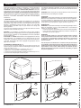
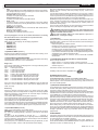
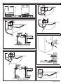
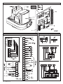
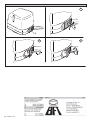
D811415 ver.04
I
07/03/05
AUTOMAZIONI A BRACCIO PER CANCELLI A BATTENTE
GB ARM AUTOMATIONS FOR SWING GATES
F
AUTOMATIONS A BRAS POUR PORTAILS BATTANTS
D
ARM AUTOMATIONEN FUER FLUGELGITTERTIRE
E
AUTOMATIZACIONES A BRAZO PARA PORTONES CON BATIENTE
P
AUTOMATIZAÇÕES DE BRAÇO PARA PORTÕES DE BATENTE
8 027908 228680
VIRGO
ISTRUZIONI D'USO E DI INSTALLAZIONE
INSTALLATION AND USER'S MANUAL
INSTRUCTIONS D'UTILISATION ET D'INSTALLATION
INSTALLATIONS-UND GEBRAUCHSANLEITUNG
INSTRUCCIONES DE USO Y DE INSTALACION
INSTRUÇÕES DE USO E DE INSTALAÇÃO
Via Lago di Vico, 44
36015 Schio (VI)
Tel.naz. 0445 696511
Tel.int. +39 0445 696533
Fax 0445 696522
Internet: www.bft.it
E-mail: [email protected]
USER’S MANUAL
Thank you for buying this product. Our company is sure that you will be
more than satisfied with the product’s performance. Carefully read the
“WARNINGS” pamphlet and the “INSTRUCTION BOOKLET” which are
supplied together with this product, since they provide important information
regarding the safety, installation, use and maintenance of the product. This
product complies with recognised technical standards and safety regulations.
We declare that this product is in conformity with the following European
Directives: 73/23/ EEC, 89/336/EEC, 98/37/EEC and subsequent
amendments.
1) GENERAL OUTLINE
Low-voltage operator (24Vdc) suitable for residential use. Designed for
swing gates having small-sized pillars. The operating arm, with its special
antishearing shape, allows the leaves to be manoeuvred even when the
operator is positioned well away from their fulcrum. The irreversible
electromechanical gearmotor keeps the gate locked in the closing and
opening positions.
The release lever, fitted to the outside of each operator, allows the manual
manoeuvre to be carried out very easily.
WARNING! The installation, the maintenance and the repair should be
done by responsible and qualified persons with an updated knowledge of
the current safety standards. It’s strictly forbidden to service the automation
when the power is on.
ATTENTION! The VIRGO model controller is not equipped with mechanical
torque adjustment. It is compulsory to use a control panel of the same
manufacturer, in compliance with the basic safety requirements of directives
73/23/CEE, 89/336/CEE, 98/37/CEE equipped with appropriate electric
adjusment of the torque.
2) EMERGENCY MANOEUVRE (Fig. 1)
In the case where the power supply is off, or any faults are present, the
manual emergency manoeuvre can be carried out by operating the external
release lever (Fig.1 ref.”S”).
1) Insert the release key and turn it clockwise (Fig.1 ref.”1”).
2) Move lever “S” until the lock is released (Fig.1 ref.”2”).
3) Keep the lever in the release position by turning the key clockwise (Fig.1 ref.”3”).
4) Push the leaf slowly to open or close the gate.
To reactivate motor-driven operation, turn the key clockwise to free the
lever from its released position, then return it to its initial position for normal
operation.
WARNING! Before carrying out the manual manoeuvre make sure that this
operation will not create dangerous situations.
SCRAPPING
WARNING! This operation should only be carried out by qualified personnel.
Materials must be disposed of in conformity with the current regulations.
In case of scrapping, the automation devices do not entail any particular
risks or danger. In case of materials to be recycled, these should be sorted
out by type (electrical components, copper, aluminium, plastic etc.).
DISMANTLING
WARNING! This operation should only be carried out by qualified personnel.
When the automation system is disassembled to be reassembled on
another site, proceed as follows:
• Disconnect the power supply and the entire external electrical installation.
• In the case where some of the components cannot be removed or are
damaged, they must be replaced.
WARNINGS
Correct controller operation is only ensured when the data contained
in the present manual are observed. The company is not to be held
responsible for any damage resulting from failure to observe the
installation standards and the instructions contained in the
present manual.
The descriptions and illustrations contained in the present manual
are not binding. The Company reserves the right to make any alterations
deemed appropriate for the technical, manufacturing and commercial
improvement of the product, while leaving the essential product
features unchanged, at any time and without undertaking to update
the present publication.
Fig. 1
1
S
2
4 - VIRGO Ver. 04
3
D811415_04
ENGLISH
INSTALLATION MANUAL
Thank you for buying this product. Our company is sure that you will be
more than satisfied with the product’s performance.
Carefully read the “WARNINGS” pamphlet and the “INSTRUCTION
BOOKLET” which are supplied together with this product, since they
provide important information regarding the safety, installation, use and
maintenance of the product. This product complies with recognised technical
standards and safety regulations. We declare that this product is in
conformity with the following European Directives: 73/23/ EEC, 89/336/
EEC, 98/37/EEC and subsequent amendments.
1) GENERAL SAFETY
WARNING! An incorrect installation or improper use of the product
can cause damage to persons, animals or things.
• The “Warnings” leaflet and “Instruction booklet” supplied with this
product should be read carefully as they provide important information
about safety, installation, use and maintenance.
• Scrap packing materials (plastic, cardboard, polystyrene etc) according
to the provisions set out by current standards. Keep nylon or polystyrene
bags out of children’s reach.
• Keep the instructions together with the technical brochure for future
reference.
• This product was exclusively designed and manufactured for the use
specified in the present documentation. Any other use not specified in
this documentation could damage the product and be dangerous.
• The Company declines all responsibility for any consequences resulting
from improper use of the product, or use which is different from that
expected and specified in the present documentation.
• Do not install the product in explosive atmosphere.
• The construction components of this product must comply with the
following European Directives: 89/336/CEE, 73/23/EEC, 98/37/EEC and
subsequent amendments. As for all non-EEC countries, the abovementioned standards as well as the current national standards should
be respected in order to achieve a good safety level.
• The Company declines all responsibility for any consequences resulting
from failure to observe Good Technical Practice when constructing closing
structures (door, gates etc.), as well as from any deformation which might
occur during use.
• The installation must comply with the provisions set out by the following
European Directives: 89/336/CEE, 73/23/EEC, 98/37/EEC and
subsequent amendments.
• Disconnect the electrical power supply before carrying out any work on
the installation. Also disconnect any buffer batteries, if fitted.
• Fit an omnipolar or magnetothermal switch on the mains power supply,
having a contact opening distance equal to or greater than 3,5 mm.
• Check that a differential switch with a 0.03A threshold is fitted just before
the power supply mains.
• Check that earthing is carried out correctly: connect all metal parts for
closure (doors, gates etc.) and all system components provided with an
earth terminal.
• Fit all the safety devices (photocells, electric edges etc.) which are needed
to protect the area from any danger caused by squashing, conveying
and shearing, according to and in compliance with the applicable
directives and technical standards.
• Position at least one luminous signal indication device (blinker) where it
can be easily seen, and fix a Warning sign to the structure.
• The Company declines all responsibility with respect to the automation safety
and correct operation when other manufacturers’ components are used.
• Only use original parts for any maintenance or repair operation.
• Do not modify the automation components, unless explicitly authorised
by the company.
• Instruct the product user about the control systems provided and the
manual opening operation in case of emergency.
• Do not allow persons or children to remain in the automation operation
area.
• Keep radio control or other control devices out of children’s reach, in
order to avoid unintentional automation activation.
• The user must avoid any attempt to carry out work or repair on the
automation system, and always request the assistance of qualified
personnel.
• Anything which is not expressly provided for in the present instructions,
is not allowed.
• Installation must be carried out using the safety devices and controls
prescribed by the EN 12978 Standard.
2) GENERAL OUTLINE
Low-voltage operator (24Vdc) suitable for residential use. Designed for
swing gates having small-sized pillars. The operating arm, with its special
antishearing shape, allows the leaves to be manoeuvred even when the
operator is positioned well away from their fulcrum. The irreversible
electromechanical gearmotor keeps the gate locked in the closing and
opening positions.
16 - VIRGO Ver. 04
The release lever, fitted to the outside of each operator, allows the manual
manoeuvre to be carried out very easily.
WARNING! The installation, the maintenance and the repair should be
done by responsible and qualified persons with an updated knowledge of
the current safety standards. It’s strictly forbidden to service the automation
when the power is on.
ATTENTION! The VIRGO model controller is not equipped with mechanical
torque adjustment. It is compulsory to use a control panel of the same
manufacturer, in compliance with the basic safety requirements of directives
73/23/CEE, 89/336/CEE, 98/37/CEE equipped with appropriate electric
adjusment of the torque.
Before carrying out the manual manoeuvre make sure that this operation
will not create a dangerous situations.
Check in the relevant literature that the thermal field in the working area is
suitable for the operator.
Make sure that the movement of the door does not cause entrapment
risks between the movable and fixed parts of the door.
If swing gates with built-in doors are used, the motor must not run when
the door is left open.
WARNING! The operator must be installed by a qualified technician as
special safety components are used for every specific site and therefore
safety depends on installation.
3) TECHNICAL SPECIFICATIONS
3.1) VIRGO OPERATOR
Motor: ............................................................................ 24Vd.c. 2500 min-1
Power: .................................................................................................. 40W
Insulation class: ........................................................................................ F
Lubrication: ................................................................... Permanent grease
Reduction ratio: ............................................................................... 1-1224
Output shaft revolutions: ......................................................... 2 min-1 MAX
Opening time 90°: ................................................................................. 14s
Torque supplied: ............................................................................ 170 Nm
Max leaf weight and length: .................. 2000N (~200kg) for 2m long leaf
Impact reaction: ................................................... Integrated torque limiter
................................................................................. on LINX control panel
Motion drive: ............................................................................... Lever arm
Stop: ................. Incorporated electrical limit switches + mechanical locks
Manual manoeuvre: ....................................... Release lever with CLS key
Number of manoeuvres in 24h: .............................................................. 60
Environmental conditions: ............................................ from -15 to +50 °C
Degree of protection: .......................................................................... IPX4
Operator weight: ................. VIRGO:80N (~8kg) - VIRGO SQ:60N (~6kg)
Dimensions: .................................................................................. see fig.1
3.2) LINX CONTROL PANEL
Power supply: ......................................................... 230Va.c. ±10% 50Hz*
Mains/low voltage insulation: ....................................... > 2MOhm 500Vdc
Working temperature .................................................... from -15 to +50 °C
Dielectric strength: ................................ mains/l.v. 3750Va.c. for 1 minute
Motor output current: ......................................................... 3.5A+3.5A max
Motor relay commutation current: ........................................................ 10A
Maximum motor power: ....................................................... 40W (24Vd.c.)
Power supply for accessories: ............. 24Va.c. (180mA max absorption)
....................................................... 24Va.c.safe (180mA max absorption)
Gate-open warning light: .......................... N.O. contact (24Va.c./1A max)
Blinker: ........................................................................... 24Va.c. 25W max
Dimensions: ............................................................................. see figure 1
Fuses: ...................................................................................... see fig.9-15
(*other voltages available on request)
3.3) VIRGO BAT BATTERY KIT (OPTIONAL - Fig.14)
Allows operation to continue even when the mains power supply is off for
a short time.
Charge voltage: ........................................................................... 27.2Vd.c.
Charge current: ............................................................................... 130mA
Data detected with external temperature of: ...................................... 25°C
Battery capacity: ................................................................. 2x (12V 1.2Ah)
Exhausted battery protection threshold: ..................................... 20.4Vd.c.
Battery recharge time: .................................................................... 12/14 h
NOTE: In case of operation with battery back up, the outputs to terminals
8-9 (Vsafe 24Va.c.) and 10-11 (Vsafe 24Va.c.) show a voltage of 24Vd.c.
polarised as indicated in Fig.16.
At the time of installing the VIRGO BAT Kit, check that the safety devices
are connected correctly.
D811415_04
ENGLISH
D811415_04
INSTALLATION MANUAL
4) OPERATOR INSTALLATION
4.1) Preliminary checks
Check that:
• The gate structure is sufficiently sturdy and rigid.
The fixing position must be worked out according to the leaf structure. In
any case, the manoeuvring arm must push against a reinforced leaf
point.
• The leaves can be moved manually along their entire stroke.
If the gate has not been installed recently, check the wear condition of all
its components. Repair or replace defective and worn parts.
Operator reliability and safety are directly affected by the condition of
the gate structure.
5) SUPPORT PLATE FIXING (Fig.5)
The operator is supplied with a fixing bracket and lever arm.
Having identified the leaf reinforcement point, with the gate closed, trace an
imaginary horizontal line from the centre of the reinforcement point to the
pillar (fig. 3-4).
Fig. 2 illustrates the most common types of installation:
- with the leaf hinge pivot not aligned with the fixing plate
(90° opening – maximum distance between hinge pivot and plate:
210mm)
- with the hinge pivot aligned with the fixing plate
Position the anchoring bracket observing the dimensions shown in fig.3 for
opening up to 90°, or in fig.2-4 for opening over 90° up to a max of 120°.
The pillar surface, where the bracket is fixed, must be flat and parallel to the
leaf. Use screws and expansion plugs adequate for the type of pillar. In the
case where the pillar surface is irregular, use expansion plugs with studs,
in order to be able to adjust the fixing bracket parallel to the leaf (fig.5).
•
•
•
•
•
•
•
•
Assemble the lever arm as in fig.7.
DX = fitting to right leaf
SX = fitting to left leaf
Choose the most suitable position for fixing bracket “F” to the leaf.
Insert lever L into the gearmotor output shaft, and fix it using appropriate
pivot P and self-locking nut D (fig.7).
Release the operator by activating the release lever to allow the arm to
move easily (see paragraph “EMERGENCY MANOEUVRE”).
Open the gearmotor cover and fix it to the plate as indicated in Fig.8.
Fix towing angle bar “F” to the leaf.
The correct position for the operator arm is illustrated in fig.6. The leaf
attachment point can be identified by positioning the arm according to
the dimension indicated in fig.6.
With the operator released, check the arm for correct movement.
Repeat the same procedure for the other leaf.
6) BACKSTOP FIXING
The VIRGO operator is provided with mechanical end-of-stroke backstops,
which make the installation of ground stop plates redundant.
With reference to Fig. 10 proceed as follows:
- Identify the opening and closing end-of-stroke points and fix the backstops
accordingly.
- Fix protection cover C.
7) ELECTRICAL INSTALLATION SET-UP
Arrange the electrical installation as shown in fig.11.
Keep the mains voltage connections definitely separate from the very low
voltage connections (24V).
For this purpose, the operator is provided with appropriate fittings, indicated
in Fig.9, for a spiral flexible raceway with an inside diameter of 20:
- P1 input for mains power supply + GND.
- P2/P3 inputs for safety devices and accessories.
For the mains power supply, use the appropriate cable clamp (Fig.9 -”S”),
the terminal bar with an incorporated protection fuse (Fig.9 -”L-N”) and the
GND terminal.
Connect the yellow/green cable to the earth terminal.
Fig.16 shows the cross-section and the number of connections.
8) TERMINAL BAR CONNECTIONS (Fig.16)
NOTE: The VIRGO operators provided with incorporated LINX control
panels are preset for fitting to the left leaf, whereas the operators
without panels (VIRGO-SQ) are preset for fitting to the right leaf, as
illustrated by the example given in Fig.11.
Should it be necessary to reverse the operator opening direction, proceed
as follows:
1 – Reverse motor polarity (JP1 terminals 1-2)
2 – Reverse motor polarity (JP2 terminals 14-15)
WARNING – During the wiring and installation operations, refer to the
ENGLISH
current standards as well as principles of good technical practice.
The (24V) very low voltage conductors must be physically separated from
the low voltage conductors or otherwise be adequately isolated by means
of an additional insulation of at least 1 mm.
The wires must be clamped by an extra fastener near the terminals, for
example by bands.
All the connection cables must be kept at an adequate distance from the
dissipator(Fig.15 “D”).
WARNING! For connection to the mains, use a multipolar cable with
a minimum of 3x1.5mm2 cross section and complying with the
previously mentioned regulations. For example, if the cable is out side
(in the open), it has to be at least equal to H07RN-F, but if it is on the
inside (or outside but placed in a plastic cable cannel) it has to be or
at least egual to H05VV-F with section 3x1.5mm2.
JP1
1-2
3-5
4-5
6-7
JP2
8-9
10-11
12-13
14-15
16-18
17-18
19-24
20-24
21-24
22-24
23-24
25-26
27-28
Motor 2 connection (VIRGO with LINX panel):
Opening limit switch SWO M2 (N.C.)
Closing limit switch SWC M2 (N.C.)
24 Va.c. power supply input from the transformer
24Va.c. Vsafe 180mA max output – power supply for photocell
transmitters with check (Fig.17)
24Va.c. 180mA max output – power supply for photocells or other
devices
Blinker connection (24Va.c. 25W max)
Motor 1 connection (VIRGO-SQ – without LINX panel -):
Opening limit switch SWO M1 (N.C.)
Closing limit switch SWC M1 (N.C.)
Pedestrian opening button PED (N.O.). Controls partial opening
of Motor M2.
Fault input (N.O.). Input for photocells or safety devices provided
with an N.O. check contact.
Photocell input (N.C.). If not used, leave bridged (Fig.17).
STOP button (N.C.). If not used, leave bridged.
START button (N.O.).
Output for gate-open warning light (N.O. contact (24Va.c./1A
max) or alternatively for 2nd radio channel (see configuration “logics” menu)
Antenna input for incorporated radio-receiver board (27 braid - 28
signal).
9) PROGRAMMING
The control panel provided with a microprocessor is supplied with function
parameters preset by the manufacturer, suitable for standard installations.
The predefined parameters can be altered by means of either the
incorporated display programmer or UNIPRO.
In the case where programming is carried out by means of UNIPRO,
carefully read the instructions relating to UNIPRO, and proceed in the
following way.
Connect the UNIPRO programmer to the control unit through the UNIFLAT
and UNIDA accessories (See fig. 18). The LINX control unit does not supply
the UNIPRO programmer with power, and therefore requires an appropriate
supply unit.
Enter the “CONTROL UNITS” menu, and the “PARAMETERS” submenu,
then scroll the display screenfuls using the up/down arrows to set the
numerical values of the parameters listed below.
For the function logics, refer to the “LOGIC” submenu.
In the case where programming is carried out by means of the incorporated
programmer, refer to Fig. A and B and to the paragraph on “Configuration”.
10) CONFIGURATION
The display programmer is used to set all the LINX control panel functions.
The programmer is provided with three pushbuttons for menu scrolling and
function parameter configuration:
+
menu scrolling/value increment key
menu scrolling/value reduction key
OK Enter (confirm) key
The simultaneous pressure of the + and - keys is used to exit the active
menu and move to the preceding menu.
The modifications made are only set if the OK key is subsequently pressed.
When the OK key is pressed for the first time, the programming mode is
entered.
VIRGO Ver. 04 - 17
INSTALLATION MANUAL
The following pieces of information appear on the display at first:
- Control unit software version
- Number of total manoeuvres carried out (the value is expressed in
thousands, therefore the display constantly shows 0000 during the first
thousand manoeuvres)
- Number of manoeuvres carried out since the latest maintenance
operation (the value is expressed in thousands, therefore the display
constantly shows 0000 during the first thousand manoeuvres)
- Number of memorised radio control devices.
When the OK key is pressed during the initial presentation phase, the first
menu can be accessed directly.
Here follows a list of the main menus and the respective submenus available.The
predefined parameter is shown between square brackets [ 0 ].
The writing appearing on the display is indicated between round brackets.
Refer to Figures A and B for the configuration procedure.
10.1) PARAMETER MENU (PARAm)
- Automatic Closing Time (TCA) [ 10s ]
Set the numerical value of the automatic closing time from 3 to 60
seconds.
- Motor 1 torque (m1 t) [ 50% ]
(UNIPRO ⇒ Advanced parameters ⇒ address 3)
Set the numerical value of the motor 1 torque between 1% and 99%.
- Motor 2 torque (m2 t) [ 50% ]
(UNIPRO ⇒ Advanced parameters ⇒ address 4)
Set the numerical value of the motor 2 torque between 1% and 99%.
- Motor 1 slow-down torque (m1 t slow) [ 45% ]
(UNIPRO _ Advanced parameters _ address 8)
Set the numerical value for slow-down torque of motor 1 between 1%
and 99%.
- Motor 2 slow-down torque (m2 t slow) [ 45% ]
(UNIPRO _ Advanced parameters _ address 9)
Set the numerical value for slow-down torque of motor 2 between 1%
and 99%.
NOTES: In case of obstacle detection, the Ampere-stop function stops
the leaf movement, reverses the motion for 1 sec. and then halts in the
STOP status. The motor slow-down torque represents the maximum
torque supplied to the motor during the slow-down phase. It must be set
to a lower value with respect to the motor torque, in order to allow the
Ampere-stop function to be also activated during the slow-down phase.
WARNING: Check that the impact force value measured at
the points established by the EN 12445 standard is lower
than that specified in the EN 12453 standard.
Incorrect sensitivity setting can cause injuries to persons or
animals, or damage to things.
- Opening delay time (open delay time) [ 1s ]
Set the opening delay time for motor 2 relative to motor 1, between 1
and 10 seconds.
- Closing delay time (cls delay time) [ 1s ]
Set the closing delay time for motor 1 relative to motor 2, between 1 and
10 seconds.
- Motor 1 Normal Speed Time (m1 fast time) [ 5s ]
(UNIPRO fi Advanced parameters fi address 6)
Set the time to normal speed (not slowed down), ranging from 1 to 30
seconds.
- Motor 2 Normal Speed Time (m2 fast time) [ 5s ]
(UNIPRO fi Advanced parameters fi address 7)
Set the time to normal speed (not slowed down), ranging from 1 to 30
seconds.
Note: The slow-down time, on closing and on opening, is obtained by
timing one manoeuvre, and setting a lower value within this parameter.
If, for example, one manoeuvre lasts 25 seconds, set “normal speed
time” to 20s to obtain 5s of slow-down time, both on closing and on
opening.
- Slow-down speed (slov speed) [ 2 ]
(UNIPRO ⇒ Advanced parameters ⇒ address 5)
Set the slow-down speed by choosing from the following values:
0 – slow-down disabled
1 – slow-down to 50% of normal speed
2 – slow-down to 33% of normal speed.
3 – slow-down to 25% of normal speed.
m
m
10.2) LOGIC MENU (logic.)
- TCA (TCA) [ OFF ]
ON Activates automatic closing
OFF Excludes automatic closing
- 3 Steps (3 step) [ OFF ]
ON Enables 3-step logic. A Start impulse has the following effects:
18 - VIRGO Ver. 04
door closed:
opens
on opening:
stops and enters TCA (if configured)
door open:
closes
on closing:
stops and reopens
OFF Enables 4-step logic. A Start impulse has the following effects:
door closed: opens
on opening:
stops and enters TCA (if configured)
door open:
closes
on closing:
stops and does not enter TCA (stop)
after stopping: opens
- Impulse lock (ibl open) [ OFF ]
ON The Start impulse has no effect during the opening phase.
OFF The Start impulse becomes effective during the opening or closing
phase.
- Rapid closing (fast cls) [ OFF ]
ON Closes the gate after photocell disengagement, before waiting for
the end of the TCA set.
OFF Command not entered.
- Photocells on opening (photc. open) [ OFF ]
ON:
In case of obscuring, this excludes photocell operation on opening.
During the closing phase, it immediately reverses the motion.
OFF: In case of obscuring, the photocells are active both on opening and
on closing. When a photocell is obscured on closing, it reverses the
motion only after the photocell is disengaged.
- Photocell test (test phot) [ OFF ]
(UNIPRO ⇒ Advanced logics ⇒ address 14)
ON Activates photocell check
OFF Deactivates photocell check
If this setting is not activated (OFF), it inhibits the photocell checking
function, allowing connection of devices not provided with additional
checking contact.
- Gate-open or 2nd radio channel warning light (SCA 2ch) [ OFF ]
ON The output between terminals 25 and 26 is configured as Gate-open
warning light, in this case the 2nd radio channel controls pedestrian
opening.
OFF The output between terminals 25 and 26 is configured as 2nd radio
channel.
- Motors in operation (1 mot ON) [ OFF ]
ON Only motor 2 is in operation (terminals 1 and 2).
With this configuration, the pedestrian input is disabled.
OFF Both motors are in operation.
Lock hold (bloc persist) [ OFF ]
ON To be used when opening and closing mechanical backstops are
fitted.
This function activates leaf pressure on the backstop, without this
being considered as an obstacle by the ampere-stop sensor.
Then the leaf continues its stroke for another 0,5s, after intercepting
the limit switches. Therefore the limit switches are triggered slightly
in advance, and the leaves will stop perfectly on the end stop plate.
OFF To be used when no mechanical backstops are fitted.
Movement is exclusively stopped by the limit switches being triggered;
in this case it is necessary to set the opening and closing limit switch
triggering point with precision.
Prealarm (preal) [ OFF ]
ON The blinker comes on about 3s before the motors start.
OFF The blinker comes on at the same time as the motors start
- Fixed code (fixed code) [ OFF ]
(UNIPRO ⇒ Advanced logics ⇒ address 13)
ON The receiver is configured for operation in fixed-code mode, see
paragraph on “Radio Transmitter Cloning”.
OFF The receiver is configured for operation in rolling-code mode, see
paragraph on “Radio Transmitter Cloning”.
- Radio transmitter programming (radio prog) [ ON ]
(UNIPRO ⇒ Advanced logics ⇒ address 15)
ON This enables transmitter storage via radio:
1 – First press the hidden key (P1) and then the normal key (T1, T2,
T3 or T4) of a transmitter already memorised in standard mode by
means of the radio menu.
2 – Within 10s press the hidden key (P1) and the normal key (T1, T2,
T3 or T4) of a transmitter to be memorised.
The receiver exits the programming mode after 10s, other new
transmitters can be entered before the end of this time.
This mode does not require access to the control panel.
OFF This disables transmitter storage via radio.
The transmitters can only be memorised using the appropriate Radio
menu.
10.3) RADIO MENU (RADIO)
D811415_04
ENGLISH
D811415_04
INSTALLATION MANUAL
-
-
-
-
Add
Allows you to add one key of a radio control device to the receiver memory;
after storage it displays a message showing the receiver number in the
memory location (from 01 to 64).
Add Start button (add start)
associates the required key to Start command
Add 2ch button (add 2ch)
associates the required key to 2nd radio channel
Read (read)
Checks one key of a receiver; if stored it displays a message showing
the receiver number in the memory location (from 01 to 64), and the key
number (T1, T2, T3 or T4).
Eliminate list (erease 64)
WARNING! Completely removes all memorised radio control devices
from the receiver memory.
Receiver code reading (RX code)
This displays the code entered in the receiver.
Consult paragraphs 12-13-14-15 for further information concerning
the advanced functions of the Clonix incorporated receiver.
10.4) LANGUAGE MENU (language)
Allows you to set the language on the display programmer.
- ITALIAN (ITA)
- FRENCH (FRA)
- GERMAN (DEU)
- ENGLISH (ENG)
- SPANISH (ESP)
10.5) DEFAULT MENU (default)
Restores the preset default values on the control unit. After restoring, a new
autoset operation must be carried out.
10.6) DIAGNOSTICS AND MONITORING
The display on the LINX panel shows some useful information, both during
normal operation and in the case of malfunctions.
Diagnostics:
In the case of malfunctions, the display shows a message indicating which
device needs to be checked:
PED
= PED input activation
STRT
= START input activation
STOP
= STOP input activation
PHOT = PHOT input activation
FLT
= FAULT input activation for checked photocells
SWO1 = activation of Motor 1 opening limit switch input
SWC1 = activation of Motor 1 closing limit switch input
SWO2 = activation of Motor 2 opening limit switch input
SWC2 = activation of Motor 2 closing limit switch input
In the case where an obstacle is found, the LINX panel stops the door and
activates a reverse manoeuvre; at the same time the display shows the
“AMP” message.
Monitoring:
During the opening and closing phases, the display shows four digits
separated by a dot, for example 35.40. The digits are constantly updated
during the manoeuvre, and represent the maximum torque reached by
motor 1 (35) and motor 2 (40).
These values allow the torque setting to be corrected.
If the maximum torque value reached during the manoeuvre gets sensibly
close to the value set in the parameter menu, malfunctions may occur in the
future following wear or slight door deformation.
It is therefore advisable to check the maximum torque reached during some
of the manoeuvres carried out in the course of installation, and if necessary
set a value about 15-20 percent points higher in the parameter menu.
10.7) AUTOSET MENU (autoset)
Allows you to automatically set the Motor torque.
WARNING!! The autoset operation is only to be carried out after checking
the exact leaf (opening/closing) movement, and correct limit-switch
activation.
As soon as the OK pushbutton is pressed, the “.... ....” message is
displayed, and the control unit executes an opening manoeuvre followed by
a closing manoeuvre, during which the minimum torque value needed for
leaf movement is automatically set.
During this phase, it is important to avoid obscuring the photocells, as well
as using the START, STOP or PED commands and the display.
ENGLISH
After this, if autosetting has been successfully completed, the control unit
displays the “OK” message and, after pressing any key, returns to the
Autoset menu.
If, on the other hand, the control unit displays the “KO” message, it means
that the autoset procedure has not been successfully completed; it is thus
necessary to check the wear condition of the gate and the regular movement
of the leaves before proceeding to a new autoset operation.
WARNING! During the autoset phase, the obstacle detection function is not
active, therefore the installer must control the automation movement and
prevent persons and things from approaching or standing within the
automation working range.
In the case where buffer batteries are used, autosetting must be carried out
with the control panel supplied by mains power voltage.
m
m
WARNING: Check that the impact force value measured at the
points established by the EN 12445 standard is lower than that
specified in the EN 12453 standard.
Incorrect sensitivity setting can cause injuries to persons or
animals, or damage to things.
11) STATISTICS
Having connected the UNIPRO programmer to the control unit, enter the
CONTROL UNIT / STATISTICS menu and scroll the screenful showing the
statistical parameters:
- Board microprocessor software version.
- Number of cycles carried out. If motors are replaced, count the number
of manoeuvres carried out up to that time.
- Number of cycles carried out from the latest maintenance operation.
It is automatically set to zero after each self-diagnosis or parameter writing.
- Date of latest maintenance operation. To be updated manually from the
appropriate menu “Update maintenance date”.
- Installation description. 16 characters can be entered for installation
identification.
12) INTEGRATED RECEIVER TECHNICAL SPECIFICATION
Receiver output channels:
- output channel 1, if activated, controls a START command.
- output channel 2, if activated, controls the excitation of the 2nd radio
channel relay for 1s.
Transmitter versions which can be used:
all Rolling Code transmitters compatible with
ANTENNA INSTALLATION
Use an antenna tuned to 433MHz.
For Antenna-Receiver connection, use RG8 coaxial cable.
The presence of metallic masses next to the antenna can interfere with
radio reception. In case of insufficient transmitter range, move the antenna
to a more suitable position.
13) RECEIVER CONFIGURATION
The on-board receiver combines characteristics of utmost safety in copying
variable code (rolling code) coding with the convenience of carrying out
transmitter “cloning” operations thanks to an exclusive system.
Cloning a transmitter means creating a transmitter which can be automatically
included within the list of the transmitters memorised in the receiver, either
as an addition or as a replacement of a particular transmitter.
Cloning by replacement is used to create a new transmitter which takes the
place of the one previously memorised in the receiver; in this way a specific
transmitter can be removed from the memory and will no longer be usable.
Therefore it will be possible to remotely program a large number of
additional transmitters or, for example, replacement transmitters for those
which have been lost, without making changes directly to the receiver.
When coding safety is not a decisive factor, the on-board receiver allows
you to carry out fixed-code additional cloning which, although abandoning
the variable code, provides a high number of coding combinations, therefore
keeping it possible to “copy” any transmitter which has already been
programmed .
PROGRAMMING
Transmitter storage can be carried out in manual mode or by means of the
UNIRADIO programmer which allows the complete installation database to
be managed through the Eedbase software.
In this second case, receiver programming takes place through the
connection of UNIRADIO to the LINX control panel, using the UNIFLAT and
UNIDA accessories as indicated in Fig. 18.
VIRGO Ver. 04 - 19
INSTALLATION MANUAL
14) MANUAL PROGRAMMING
In the case of standard installations where advanced functions are not
required, you can proceed to manual storage of the transmitters, making
reference to fig. B for basic programming.
-
-
If you wish the transmitter to activate output 1 (START) by means of
key1, key2, key3 or key4, enter the transmitter in menu “Start key”, as
in fig. B.
If you wish the transmitter to activate output 2 (2nd radio channel relay)
by means of key1, key2, key3 or key4, enter the transmitter in menu “2nd
ch. key”, as in fig. B.
Note: Hidden key P1 appears differently depending on the transmitter model.
For transmitters with hidden key, press hidden key P1 (fig. B1). For
transmitters without hidden key, the key P1 function corresponds to
simultaneously pressing the 4 transmitter keys or, after opening the
battery compartment, bridging the two P1 points by means of a screwdriver
(fig. B2).
IMPORTANT NOTE: ATTACH THE ADH ESIVE KEY LABEL TO THE
FIRST MEMORISED TRANSMITTER (MASTER).
In the case of manual programming, the first transmitter assigns the key
code to the receiver; this code is necessary in order to carry out subsequent
cloning of the radio transmitters.
15) RADIO-TRANSMITTER CLONING
Rolling-code cloning / Fixed-code cloning
Make reference to the UNIRADIO Instructions and the CLONIX Programming
Guide.
15.1) ADVANCED PROGRAMMING: COLLECTIVE RECEIVERS
Make reference to the UNIRADIO Instructions and the CLONIX Programming
Guide.
16) LIMIT SWITCH ADJUSTMENT (Fig.12)
• Identify the opening and closing limit switches (FC1 and FC2) taking into
account that:
FC1 corresponds the CLOSING limit switch
FC2 corresponds the OPENING limit switch.
• With the gate completely closed or opened, rotate the corresponding
cam until the relevant limit microswitch is heard being tripped, then lock
the cam into position by means of the appropriate screws.
• Check that the limit switches are triggered correctly, by initiating a few
complete motor-driven opening and closing cycles.
• If the “lock hold” logic is set to ON in the LINX panel, the leaf continues
its stroke for about 0,5 seconds, in order to ensure stability and perfect
leaf stopping against the end-of-stroke backstops.
17) EMERGENCY MANOEUVRE (Fig.19)
In the case where the power supply is off, or any faults are present, the
manual emergency manoeuvre can be carried out by operating the external
release lever (Fig.1 ref.”S”).
1) Insert the release key and turn it clockwise (Fig.19 ref.”1”).
2) Move lever “S” until the lock is released (Fig.19 ref.”2”).
3) Keep the lever in the release position by turning the key clockwise
(Fig.19 ref.”3”).
4) Push the leaf slowly to open or close the gate.
To reactivate motor-driven operation, turn the key clockwise to free the
lever from its released position, then return it to its initial position for normal
operation.
18) MANUAL WIRE RELEASE DEVICE (Fig.13)
The manual emergency release can be operated by a wire device:
- Take all the metal cable out of the sheath and insert it into the release lever.
- Lock the sheath and suitably adjust its position by means of the
appropriate screw.
- The cover is provided with a section to be torn off for the sheath to go
through.
- For further information, refer to the specific instructions for the release
device.
19) VIRGO BAT KIT INSTALLATION
- Fix the SBS board on the back of the panel box by means of a screw, as
indicated in Fig.14.
- Fix the board protection box (Fig.14 - “C”) supplied with the kit.
- Position the two batteries on the supports, as indicated in Fig.14 (“A”).
- Secure the batteries using the bracket and screws supplied.
- Proceed to wire the SBS board with reference to the diagram in Fig.14.
20 - VIRGO Ver. 04
20) AUTOMATION CHECK
Before allowing the automation to be used normally, carry out the following
procedure very carefully:
• Check the correct functioning of all safety devices (limit microswitches,
photocells, sensitive edges etc.).
• Check that the thrust (anti-squash) force of the leaf is within the limits
set by current regulations.
• Check the manual opening command.
• Check the opening and closing operations with the control devices in
use.
• Check the standard and customised electronic functioning logic.
21) AUTOMATION OPERATION
Since the automation can be remote-controlled by means of a remote
control device or a start button, and so out of sight, the good working order
of all the safety devices should be checked regularly. In the event of any
anomalous functioning of the safety devices, consult a specialised technician
immediately. Keep children at a safe distance from the automation operation
area.
22) CONTROL
The automation is used for the power-operated opening and closing of the
gate. The control can be of a number of types (manual, remote-controlled,
magnetic badge access control, etc.) depending on requirements and the
characteristics of the installation. See the specific instructions for the
various control systems. Users of the automation must be instructed about
its control and operation.
23) MAINTENANCE
Disconnect the power supply when carrying out any maintenance operations.
• Lubricate the VIRGOs of the manoeuvring arm regularly.
• Clean the lenses of the photocells every so often.
• Have a qualified person (installer) check correct motor torque setting.
• In the event of any anomalous functioning which cannot be resolved,
disconnect the power supply and contact a specialised technician
(installer). Whilst the automation is out of order, activate the manual
release to allow manual opening and closing.
24) SCRAPPING
WARNING! This operation should only be carried out by qualified personnel.
Materials must be disposed of in conformity with the current regulations.
In case of scrapping, the automation devices do not entail any particular
risks or danger. In case of materials to be recycled, these should be sorted
out by type (electrical components, copper, aluminium, plastic etc.).
25) DISMANTLING
WARNING! This operation should only be carried out by qualified personnel.
When the automation system is disassembled to be reassembled on
another site, proceed as follows:
• Disconnect the power supply and the entire external electrical installation.
• In the case where some of the components cannot be removed or are
damaged, they must be replaced.
WARNINGS
Correct controller operation is only ensured when the data contained
in the present manual are observed. The company is not to be held
responsible for any damage resulting from failure to observe the
installation standards and the instructions contained in the
present manual.
The descriptions and illustrations contained in the present manual
are not binding. The Company reserves the right to make any alterations
deemed appropriate for the technical, manufacturing and commercial
improvement of the product, while leaving the essential product
features unchanged, at any time and without undertaking to update
the present publication.
D811415_04
ENGLISH
D811415_04
Fig. A
LEGENDA
ACCESS TO MENUS
+/-
+
Press the OK key
8888
OK
OK
OK
BFT
LINX 1.0
0000
0000
00
[ 00 ]
Control unit software version
No. total manoeuvres
(in thousands)
Preset value
PRG
Parameter increment/reduction
or ON/OFF commutation
/ON
/OFF
No. manoeuvres since latest
maintenance(in thousands)
No. radio control devices
memorised
Simultaneously press the + and - keys.
Simultaneous pressure of the + and – keys
allows you to exit the active menu and return
to the preceding menu; if this takes place at
the main menu level, programming is exited
and the display switched off.
The modifications made are only confirmed if
the OK key is subsequently pressed.
Message: KO! (value or function error)
Press OK key (Enter/confirm)
OK
Menu scrolling
(+ = preceding - = following)
- +
Message: Programming in progress
Message: “Wait” (enter value or function)
+/PARAM
OK
TCA
OK
[0010]
OK
PRG
OK
[0050]
OK
PRG
OK
[0050]
OK
PRG
OK
[0045]
OK
PRG
OK
[0045]
OK
PRG
OK
[0010]
OK
PRG
OK
[0010]
OK
PRG
OK
[0050]
OK
PRG
OK
[0050]
OK
PRG
OK
[0002]
OK
PRG
- +
+/-
m1 t
- +
m2 t
END
- +
m1 t slow
- +
m2 t slow
- +
- +
open delay time
- +
cls delay time
- +
m1 fast time
- +
m2 fast time
- +
slow speed
+/LOGIC.
OK
TCA
OK
[oFF]
ON
OFF
OK
PRG
OK
[off]
ON
OFF
OK
PRG
OK
[off]
ON
OFF
OK
PRG
OK
[off]
ON
OFF
OK
PRG
OK
[off]
ON
OFF
OK
PRG
OK
[off]
ON
OFF
OK
PRG
OK
[off]
ON
OFF
OK
PRG
OK
[off]
ON
OFF
OK
PRG
OK
[off]
ON
OFF
OK
PRG
OK
[off]
ON
OFF
OK
PRG
OK
[off]
ON
OFF
OK
PRG
OK
[on]
ON
OFF
OK
PRG
- +
+/-
3 step
- +
END
ibl open
- +
fast cls
- +
- +
Fotoc. open
- +
TEST PHOT
- +
SCA 2ch
- +
i Mot ON
- +
FOLLOWING MENUS
FIG. B
BLOC persist
- +
Preal
- +
fixed code
- +
radio prog
VIRGO Ver. 04 - 21
&
D @/ E
I
RADIO
:&
%&
%' %&
%'
%(
%)
:&
;<=>=0 ?@ A=?BC
H
(
'
:&
D811415_04
!"# $
%&
%'
/
I H
ADD start
FG
H
/
I H
END
release
;-+** !,+ -+.#&-+6 M K:+)L $1
-"6&$
'$1!-$( 6+8&'+
release
;-+** !,+ -+.#&-+6 M K:+)L $1
01
'$1!-$( 6+8&'+
<+(+"*+ ;J $1 -"6&$
'$1!-$( 6+8&'+
desired button
-"6&$ '$1!-$( 6+8&'+ N *++ D&2/ OP
I
<+(+"*+ ;J $1 -"6&$
desired button
-"6&$ '$1!-$( 6+8&'+ N *++ D&2/ OP
;-+** ;J K3#*,5#!!$1L $1
hidden button
FG
-"6&$
'$1!-$( 6+8&'+
01
I
ADD 2ch
H
;-+** ;J K3#*,5#!!$1L $1
hidden button
FG
01 t1
READ
H
H
;-+** !,+ -+.#&-+6 M K:+)L $1
FG
-"6&$ '$1!-$( 6+8&'+ N *++ D&2/ OP
I
I
ERASE 64
H
PRG.
FG
I
/
I H
COD RX
language
FG
1A9C
ITA
FG
H
/
I H
FG
FG
22FD
FG
01
FG
2*63, /.0+
*66 H E ( ( $ 9 * ) $ # ! $ " 6 6 $ 1 + : + ) $ 7 " - " 6 & $ ' $ 1 ! - $ (
I
6+8&'+ !$ !,+ -+'+&8+- %+%$-)Q "7!+- *!$-"2+ &! 6&*3(")*
FRA
END
H
FG
" %+**"2+ *,$9&12 !,+ -+'+&8+- 1#%5+- &1 !,+
%+%$-) ($'"!&$1 K7-$% RJ !$ STL/
H
I
Add Start button
I
N "**$'&"!+* !,+ -+.#&-+6 :+) !$
C!"-! '$%%"16
DEU
FG
Add 2ch button
N "**$'&"!+* !,+ -+.#&-+6 :+) !$ U16
-"6&$ ',"11+(
H
2.*6 H > , + ' : * $ 1 + : + ) $ 1 " - + ' + & 8 + - 4 & 7 * ! $ - + 6 & !
I
6&*3(")* " %+**"2+ *,$9&12 !,+ -+'+&8+- 1#%5+- &1
DEFAULT
FG
PRG
FG
ENG
FG
!,+ %+%$-) ($'"!&$1 K7-$% RJ !$ STL4 "16 !,+ :+)
1#%5+- KMJ4 MU4 MP $- MTL/
/
H
I H
VE<? ?@W >$%3(+!+() -+%$8+* "(( %+%$-&*+6 -"6&$
esp
H
END
.2*-. 7)
I
FG
I
'$1!-$( 6+8&'+* 7-$% !,+ -+'+&8+- %+%$-)/
8,6 29
0&*3(")* !,+ -+'+&8+- '$6+/
A":+ -+7+-+1'+ !$ 3"-"2-"3, JJ/
FG
AUTOset
FG
. . .
*+%,-.% /.0+
! "#!$%"!&'"(() *+!* !,+ %$!$- !$-.#+/
. . .
FG
/
I H
1*203045 0#-&12 !,+ "#!$*+! 3,"*+4 !,+ $5*!"'(+
6+!+'!&$1 7#1'!&$1 &* 1$! "'!&8+4 !,+-+7$-+ !,+ &1*!"((+%#*! '$1!-$( !,+ "#!$%"!&$1 %$8+%+1! "16 3-+8+1!
3+-*$1* "16 !,&12* 7-$% "33-$"',&12 $- *!"16&12
END
22 - VIRGO Ver. 04
9&!,&1 !,+ "#!$%"!&$1 9$-:&12 -"12+/
%&
%'
%(
%)
Fig. 2
180
215
335
Max. 210
230
90˚
230
Fig. 3
335
390
120
120˚
90˚
123
Fig. 5
30
300 MIN
SX
52
Fig. 4
230
390
120˚
123
Fig. 6
135
SX
52
300 MIN
D811415_04
Fig. 1
635
VIRGO Ver. 04 - 51
S
S
S
Fig. 9
Fig. 10
Fig. 11
52 - VIRGO Ver. 04
D811415_04
Fig. 8
Fig. 7
D811415_04
Fig. 12
C
VIRGO BAT
SBS
A
VIRGO Ver. 04 - 53
D811415_04
Fig. 15
JP1
Fig. 16
54 - VIRGO Ver. 04
LINX
Fig. 17
D811415_04
Fig. 18
4
LINX
UNIPRO/UNIRADIO
UNIFLAT
88
88
UNIPOWER
UNIDA
Contatti
Contacts
Contacts
Kontakte
Contactos
Contatos
UNIFLAT
Contatti
Contacts
Contacts
Kontakte
Contactos
Contatos
UNIFLAT
UNITRC
UNIFLAT
UNIMITTO
UNITRC
Contatti
Contacts
Contacts
Kontakte
Contactos
Contatos
P1P1
P1
T1
T1 2
T 3
T 4
T
TRC 1-2
T2
Led
P1
P1
P1
UNIMITTO
UNITRC
2
P1
1
Contatti
Contacts
Contacts
Kontakte
Contactos
Contatos
3
1
4
2
3
4
VIRGO Ver. 04 - 55
1
S
2
56 - VIRGO Ver. 04
3
D811415_04
Fig. 19