1
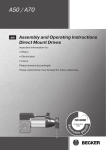
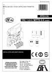
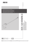
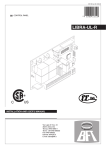
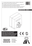
D811472 ver. 04 06-03-06
I
CENTRALINA UNIVERSALE PER IL CONTROLLO DI UNO O DUE MOTORI
GB UNIVERSAL CONTROL UNIT FOR OPERATING ONE OR TWO MOTORS
F
�
������
UNITE DE COMMANDE UNIVERSELLE POUR LE CONTROLE D’UN OU DEUX MOTEURS
D UNIVERSALSTEUERUNG FÜR EINEN ODER ZWEI MOTOREN
E CENTRAL UNIVERSAL PARA EL CONTROL DE UNO O DOS MOTORES
P CENTRAL UNIVERSAL PARA O CONTROLO DE UM OU DOIS MOTORES
RIGEL 5
ISTRUZIONI D’USO E DI INSTALLAZIONE
INSTALLATION AND USER’S MANUAL
INSTRUCTIONS D’UTILISATION ET D’INSTALLATION
INSTALLATIONS-UND GEBRAUCHSANLEITUNG
INSTRUCCIONES DE USO Y DE INSTALACION
INSTRUÇÕES DE USO E DE INSTALAÇÃO
Via Lago di Vico, 44
36015 Schio (VI)
Tel.naz. 0445 696511
Tel.int. +39 0445 696533
Fax 0445 696522
Internet: www.bft.it
E-mail: [email protected]
������
D811472_04
2 - RIGEL 5 - Ver. 04
D811472_04
MANUALE D’USO
Nel ringraziarVi per la preferenza accordata a questo prodotto, la ditta è certa
che da esso otterrete le prestazioni necessarie al Vostro uso.
Leggete attentamente l’opuscolo ”Libretto istruzioni” che lo accompagna
in quanto esso fornisce importanti indicazioni riguardanti la sicurezza,
l’installazione, l’uso e la manutenzione. Nel ringraziarVi per la preferenza
accordata a questo prodotto, la ditta è certa che da esso otterrete le prestazioni necessarie al Vostro uso. Leggete attentamente l’opuscolo ”Libretto
istruzioni” che lo accompagna in quanto esso fornisce importanti indicazioni
riguardanti la sicurezza, l’installazione, l’uso e la manutenzione.
Questo prodotto risponde alle norme riconosciute della tecnica e delle
disposizioni relative alla sicurezza. Confermiamo che esso è conforme alle
seguenti direttive europee: 73/23/CEE - 93/68/CEE , 89/336/CEE - 91/236/CEE
- 92/31/CEE - 93/68/CEE, 98/37/CEE. Per quanto applicabile, essa rispetta
le seguenti norme tecniche EN60335-1, EN12453, EN12445.
AVVERTENZE
Nelle operazioni di cablaggio ed installazione riferirsi alle norme vigenti e
comunque ai principi di buona tecnica.
AVVERTENZE
Qualunque intervento sui componenti dell’automazione deve essere eseguito
da personale qualificato (installatore).
1) GENERALITÁ
La centralina RIGEL 5 viene fornita dal costruttore con settaggio standard.
Qualsiasi variazione, deve essere impostata mediante il programmatore
UNIPRO o il display integrato. La Centralina supporta completamente il
protocollo EELINK .
Le caratteristiche principali sono:
- Controllo di uno o due motori fino a 600W di potenza.
- Regolazione elettronica della coppia.
- Frenatura elettrodinamica regolabile.
- Rallentamento della velocità all’accostamento.
- Ingressi di fine-corsa chiusura / apertura separati per ogni motore.
- Uscita per luce di zona.
- Ingressi separati per le sicurezze.
-
Uscita 12V per elettroserratura a scatto o a ventosa.
Uscita per pilotare un timer.
Ingresso orologio.
Connettore per scheda semaforo / preriscaldamento motori.
La scheda è dotata di una morsettiera di tipo estraibile per rendere più
agevole la manutenzione o sostituzione. Viene fornita con una serie di ponti
precablati per facilitare l’installatore in opera.
2) DEMOLIZIONE
Attenzione: Avvalersi esclusivamente di personale qualificato.
L’eliminazione dei materiali va fatta rispettando le norme vigenti. Nel caso di
demolizione, non esistono particolari pericoli o rischi derivanti dal prodotto
stesso. È opportuno, in caso di recupero dei materiali, che vengano separati
per tipologia (parti elettriche - rame - alluminio - plastica - ecc.).
3) SMANTELLAMENTO
Attenzione: Avvalersi esclusivamente di personale qualificato.
Nel caso la centralina venga smontata per essere poi rimontata in altro
sito bisogna:
• Togliere l’alimentazione e scollegare tutto l’impianto elettrico.
• Nel caso alcuni componenti non possano essere rimossi o risultino
danneggiati, provvedere alla loro sostituzione.
USER’S MANUAL
Thank you for buying this product, our company is sure that you will be
more than satisfied with its performance. This product is supplied with an
“Instruction Manual” which should be read carefully as it provides important
information about safety, installation, operation and maintenance.
This product complies with the applicable technical standards and regulations
regarding safety. We confirm that it complies with the following European
directives: 73/23/CEE - 93/68/CEE, 89/336/CEE - 91/236/CEE - 92/31/CEE
- 93/68/CEE, 98/37/CEE. Where applicable, it also complies with technical
standards EN60335-1, EN12453, EN12445.
IMPORTANT
For the operations of wiring and installation, refer to the regulations in effect
and, in any case, to the principles of proper workmanship.
IMPORTANT
Any operation on the parts relative to automation must be carried out by
qualified personnel (the installer).
ITALIANO
ENGLISH
2) SCRAPPING
Warning: This operation should only be carried out by qualified personnel. Materials must be disposed of in conformity with the current regulations.
In case of scrapping, the automation devices do not entail any particular risks
or danger. In case of materials to be recycled, these should be sorted out by
type (electrical components, copper, aluminium, plastic etc.).
3) DISMANTLING
Warning: This operation should only be carried out by qualified personnel. When the control unit is disassembled to be reassembled on another
site, proceed as follows:
• Disconnect the power supply and the entire electrical installation.
• In the case where some of the components cannot be removed or are
damaged, they must be replaced.
1) GENERAL OUTLINE
The RIGEL 5 control unit is supplied by the manufacturer with standard
setting. Any changes must be set by means of the UNIPRO programmer or
the incorporated display.
This Control unit supports the entire EELINK protocol, including the programmer self-supply from the control unit.
These are its main features:
- Control of one or two motors up to 600W power.
- Electronic torque setting.
- Adjustable electrodynamic braking.
- End-of-run speed slow-down.
- Separate opening / closing limit-switch inputs for each motor.
- Output for zone light.
- Separate inputs for safety devices.
- 12V output for click or suction-type electric lock.
- Output for timer piloting.
- Clock input.
- Connector for traffic-light board / motor preheating.
The board is provided with a removable terminal board for easier maintenance
and replacement. This is supplied with a series of prewired jumpers to make
work easy for the installer.
RIGEL 5 - Ver. 04 -
3
D811472_04
INSTALLATION MANUAL
Thank you for buying this product, our company is sure that you will be more
than satisfied with its performance.
This product is supplied with an “Instruction Manual” which should be read
carefully as it provides important information about safety, installation, operation and maintenance.
This product complies with the applicable technical standards and regulations
regarding safety. We confirm that it complies with the following European
directives: 73/23/CEE - 93/68/CEE, 89/336/CEE - 91/236/CEE - 92/31/CEE
- 93/68/CEE, 98/37/CEE. Where applicable, it also complies with technical
standards EN60335-1, EN12453, EN12445.
IMPORTANT
For the operations of wiring and installation, refer to the regulations in effect
and, in any case, to the principles of proper workmanship.
IMPORTANT
Any operation on the parts relative to automation must be carried out by
qualified personnel (the installer).
1) AUTODIAGNOSTICS
The control unit runs a check on the operating relays and safety mechanisms (photocells, sensor ridge, etc.) before performing opening and closing
cycles.
2) CONNECTION OF PHOTOCELLS AND SENSOR RIDGE:
By convention, refer to a receiver (Rx- fig.6) with 5 terminals of which terminals
1 and 2 are for the 24V AC power supply, terminal 3 is shared, terminal 4
is the normally closed contact when at rest, terminal 5 is the normally open
contact when at rest. The contact is not powered.
•
•
•
•
•
•
•
•
•
•
•
•
ENGLISH
The Company declines all responsibility for any consequences resulting
from failure to observe Good Technical Practice when constructing closing
structures (door, gates etc.), as well as from any deformation which might
occur during use.
The installation must comply with the provisions set out by the following
European Directives: 89/336/CEE, 73/23/EEC, 98/37/EEC and subsequent
amendments.
Disconnect the electrical power supply before carrying out any work on
the installation. Also disconnect any buffer batteries, if fitted.
Fit an omnipolar or magnetothermal switch on the mains power supply,
having a contact opening distance equal to or greater than 3,5 mm.
Check that a differential switch with a 0.03A threshold is fitted just before
the power supply mains.
Check that earthing is carried out correctly: connect all metal parts for
closure (doors, gates etc.) and all system components provided with an
earth terminal.
Fit all the safety devices (photocells, electric edges etc.) which are needed
to protect the area from any danger caused by squashing, conveying and
shearing.
Position at least one luminous signal indication device (blinker) where it
can be easily seen, and fix a Warning sign to the structure.
The Company declines all responsibility with respect to the automation safety
and correct operation when other manufacturers’ components are used.
Only use original parts for any maintenance or repair operation.
Do not modify the automation components, unless explicitly authorised
by the company.
Instruct the product user about the control systems provided and the
manual opening operation in case of emergency.
Do not allow persons or children to remain in the automation operation
area.
Keep radio control or other control devices out of children’s reach, in
order to avoid unintentional automation activation.
The user must avoid any attempt to carry out work or repair on the automation system, and always request the assistance of qualified personnel.
Anything which is not expressly provided for in the present instructions,
is not allowed.
Installation must be carried out using the safety devices and controls
prescribed by the EN 12978 Standard.
3) LEGEND
RX: receiver photocells or infrared ridges.
TX: transmitter photocells or infrared ridges.
The transmitters should be connected to terminals 20-44 of RIGEL 5.
The receivers should be connected to terminals 20-21 of RIGEL 5.
- Fig.8 shows connection of RIGEL 5 with no safety device.
- Fig. 9 shows the connection of the RIGEL 5 with 1 tested photocell.
- Fig. 10 shows connection of RIGEL 5 with 1 safety device with verified
opening.
- Fig.11 shows connection of RIGEL 5 with 1 safety device with verified
closing.
- Fig. 12 shows the connection of the RIGEL 5 with 2 tested photocells
- Fig.13 shows connection of RIGEL 5 with 2 safety devices with verified
opening.
- Fig.14 shows connection of RIGEL 5 with 2 safety devices with verified
closure.
- Fig.15 shows the connection of the RIGEL 5 with 3 tested photocells
- Fig.16 shows the connection of the RIGEL 5 with 3 tested safety devices
on opening.
- Fig.17 shows the connection of the RIGEL 5 with 3 tested safety devices
on closing.
- Fig.18 shows the connection of the RIGEL 5 with 2 devices: 1 photocell
and 1 tested safety device on opening
- Fig.19 shows the connection of the RIGEL 5 with 3 devices: 1 photocell, 1
safety device on opening and 1 safety device on closing, all being tested.
- Fig.20 shows the connection of the RIGEL 5 with 4 devices: 2 photocells, 1
safety device on opening and 1 safety device on closing, all being tested.
- Fig.21 shows the connection of the RIGEL 5 with 5 devices: 3 photocells, 1
safety device on opening and 1 safety device on closing, all being tested.
•
4) GENERAL SAFETY
WARNING! An incorrect installation or improper use of the product can
cause damage to persons, animals or things.
• The “Warnings” leaflet and “Instruction booklet” supplied with this
product should be read carefully as they provide important information
about safety, installation, use and maintenance.
• Scrap packing materials (plastic, cardboard, polystyrene etc) according
to the provisions set out by current standards. Keep nylon or polystyrene
bags out of children’s reach.
• Keep the instructions together with the technical brochure for future
reference.
• This product was exclusively designed and manufactured for the use
specified in the present documentation. Any other use not specified in
this documentation could damage the product and be dangerous.
• The Company declines all responsibility for any consequences resulting
from improper use of the product, or use which is different from that
expected and specified in the present documentation.
• Do not install the product in explosive atmosphere.
• The construction components of this product must comply with the following
European Directives: 89/336/CEE, 73/23/EEC, 98/37/EEC and subsequent amendments. As for all non-EEC countries, the above-mentioned
standards as well as the current national standards should be respected
in order to achieve a good safety level.
The board is provided with a removable terminal board for easier maintenance
and replacement. This is supplied with a series of prewired jumpers to make
work easy for the installer.
The jumpers relate to the following terminals: 33-34, 35-36, 36-37, 38-39,
39-40, 41-42, 42-43, 52-55. If the above terminals are used, remove the
respective jumpers.
•
•
•
•
5) GENERAL OUTLINE
The RIGEL 5 control unit is supplied by the manufacturer with standard
setting.Any modifications must be entered using the UNIPRO programmer
or the incorporated display. This Control unit supports the entire EELINK
protocol.
These are its main features:
- Control of one or two motors up to 600W power.
- Electronic torque setting.
- Adjustable electrodynamic braking.
- End-of-run speed slow-down.
- Separate opening / closing limit-switch inputs for each motor.
- Output for zone light.
- Separate inputs for safety devices.
- 12V output for click or suction-type electric lock.
- Output for timer piloting.
- Clock input.
- Connector for traffic-light board / motor preheating.
- Incorporated radio receiver.
6) TECHNICAL SPECIFICATIONS
Power supply: .................................................................. 230V±10% 50Hz*
Mains/low voltage insulation: .......................................... > 2MOhm 500Vdc
Dielectric strength: ..................................... mains/bty 3750Vac for 1 minute
Motor output current: .......................................................... 3.5A+3.5A max
Motor relay commutation current: .......................................................... 10A
Maximum motor power: .........................................................600W + 600W
Zone/courtesy light: ................................................................... max 150W
Supply to accessories:..................................... 24Vac (1A max absorption)
Electric lock:................................................... 12Vdc (0.5A max, 2A for 3 s)
Light/alarm output with free n.o. contact: ............................ max 3A 250Vac
Gate-open warning light: ..................................................... 24Vac 3W max
Blinker:................................................................................ 230V 40W max
Dimensions: ..............................................................................see figure 1
Fuses: ....................................................................................... see figure 2
(* other voltages available on request)
RIGEL 5 - Ver. 04 -
13
INSTALLATION MANUAL
7) TERMINAL BOARD CONNECTIONS (Fig.3)
WARNINGS - For wiring and installation operations, refer to the current
standards and good technical principles.
Wires powered at different voltages must be physically separated, or suitably
insulated with at least 1 mm extra insulation. The wires must be clamped by
an extra fastener near the terminals, for example by bands.
WARNING! For connection
to the mains, use a multipolar cable with a
2
minimum of 3x1.5mm cross section and complying with the previously mentioned regulations. For example, if the cable is out side (in the
open), it has to be at least equal to H07RN-F, but if it is on the inside
(or outside but placed in a plastic cable2cannel) it has to be or at least
egual to H05VV-F with section 3x1.5mm .
JP1
1
2-3
JP2
4-5-6
39-40
41-42
42-43
JP5
20(JP3)-44
45-46-47
48-49-50
JP6
51-52
GND terminal.
230Vac±10%, 50-60Hz power supply (2 neutral, 3 phase).
Motor connection 1 (delayed opening), terminals 5-6 for motor
drive, terminal 4 common.
5-14 (JP12) Motor capacitor connection 1.
7-8-9
Motor connection 2 (delayed closing), terminals 8-9 for motor
drive, terminal 7 common.
8-15 (JP12) Motor capacitor connection 2.
N.B. If only one motor is used, use motor output 2 and configure
logic “1 active motor”.
10-11
230Vac output for blinker light (40W max) and EBP 230V modelelectric lock.
WARNING! If the SSR5 auxiliary board is used for motor
preheating, move the connection to terminals 12-13 (Fig.3)
and refer to Chap. 9.2 Logic Menu --> Blinker output.
12-13
230Vac output for zone/courtesy/blinking lights, 150W max. To
set the output, refer to paragraph 9.2 Logic Menu (“courtesy
light” and “blinking light”).
JP12
14
Motor 1 capacitor connection.
15
Motor 2 capacitor connection.
16-17
Light/alarm output with free n.o. contact, to pilot stair-light timer
or alarm signal for failed gate closure. As a light it commands an
impulse (impulse time 1 s) at the start of the operation, as an
alarm it lights up if the gate remains open for twice the TCA setting
(inhibited by dwell TCA (automatic closing time) logic = 0).
JP3
18-19
N.O. output (3W max) for 2nd radio channel or for gate-open
warning light. This light is off when the gate is closed, flashing on
closing and turned on if the gate is opening or already open.
20-21
Output 24V ac (1A max) powers accessories and photoreceivers.
20-44
Output 24V AC powers phototransmitters.
22-23
12Vdc electric lock output, with click (3-second impulse), or
suction.
24-25
Antenna input for radio receiver board (24 signal, 25 braid).
JP4
26-27
Internal Start Pushbutton (n.o.). Internal Start command for
traffic light.
27-28
Start Pushbutton (n.o.). Parallel to radio receiver relay (CH1).
External Start command for traffic light.
27-29
Pedestrian pushbutton (n.o.). Activation takes place on motor 2;
moreover, if the opening cycle has started (not from pedestrian
pushbutton), the pedestrian control has the same effect as a
Start command.
30-31
Open Pushbutton (n.o.).
30-32
Close Pushbutton (n.o.).
33-34
Lock pushbutton (n.c.). If not used, leave the jumper connected.
35-36
Input for ADMAP (dangerous movement area accessible to
the public) photocell contact (n.c.). If this is not used, leave the
jumper connected.
With ADMAP Photocell Logic = 0: In case of activation before
opening, movement is prevented; if activation occurs during
opening, movement is stopped and the opening manoeuvre is
resumed after release.
With ADMAP Photocell Logic =1: Photocell excluded on opening.
The opening movement takes place even when an obstacle is
present.
N.B.Regardless of the ADMAP Photocell Logic, photocell activation
during the closing manoeuvre causes stopping and reopening.
36-37
If not used, leave the jumper connected. Input for photocelledge
contact on opening SAFE OP(n.c.). In case of activation during
opening, the gate is stopped and partly closed. If not used, leave
the jumper connected.
38-39
Opening limit switch for motor 1 (n.c.). If not used, leave the
jumper connected.
14 - RIGEL 5 - Ver. 04
52-55
53
54
56
JP7
JP8
JP9
Closing limit switch for motor 1 (n.c.). If not used, leave the
jumper connected.
Opening limit switch for motor 2 (n.c.). If not used, leave the
jumper connected.
Closing limit switch for motor 2 (n.c.). If not used, leave the
jumper connected.
24V output for transmitters.
Connection with tested safety devices (see Fig. from 7 to 21).
Connection with tested safety devices (see Fig. from 7 to 21).
Clock input (n.o.). If the connected contact is open (n.o.), the
leaves close and get ready for normal operation. If the contact
is closed (n.c.), the leaves open and stay open until the contact
reopens. If the opening movement controlled by the TIMER is
prevented by the safety devices, gate opening can be resumed
by activating the START/OPEN control.
Input for photocelledge contact on closing SAFE CL (n.c.). In
case of activation during closing, the gate is stopped and partly
reopened. If not used, leave the jumper connected.
Photocell test input (PHOT-FAULT).
Safety edge/opening photocell test input (BAR-FAULT).
Closing photocell test input (PHOT CL-FAULT).
Radio receiver board connector.
Serial connection board connector (SCS1).
Traffic-light / Preheating SSR5 board connector.
8) PROGRAMMING
The control unit is provided with a microprocessor and supplied with operation
parameters set by the manufacturer. The predefined parameters can only
be changed by means of the UNIPRO programmer.
Before modifying the parameters, carefully read the instructions relating to
the UNIPRO programmer, and proceed as described below.
Connect the UNIPRO programmer to the control unit through the UNIFLAT
accessory (See fig.5). Enter the “CONTROL UNIT” menu and the “PARAMETERS” submenu, and scroll the display screenfuls using the up/down
arrows, then set the numerical values of the parameters listed below. For
the function logics, refer to the “LOGIC” submenu. When using the incorporated programmer for programming, make reference to Fig. A and B and the
“Configuration” paragraph. Here is a list of the meanings and values which
can be ascribed to each parameter.
9) CONFIGURATION
The display programmer is used to set all the RIGEL 5 control panel functions.
The programmer is provided with three pushbuttons for menu scrolling and
function parameter configurations (Fig. 2):
+
menu scrolling/value increment key
menu scrolling/value reduction key
OK Enter (confirm) key
The simultaneous pressure of the + and – keys is used to exit the active
menu and move to the preceding menu.
If the + and – keys are pressed simultaneously at the main menu level (parameters, logics, radio, language, autosetting), programming is exited and the
display is switched off (The END message will be displayed).
The modifications made are only set if the OK key is subsequently pressed.
When the OK key is pressed for the first time, the programming mode is entered.
The following pieces of information appear on the display at first:
- Display Software version
- Control unit Software version
- Number of total manoeuvres carried out (the value is expressed in hundreds, therefore the display constantly shows 0000 during the first cent
manoeuvres).
- Number of manoeuvres carried out since the latest maintenance operation
(the value is expressed in cent, therefore the display constantly shows
0000 during the first hundreds manoeuvres).
- Number of memorised radio control devices.
When the OK key is pressed during the initial presentation phase, the first
menu (parameters) can be accessed directly.
Here follows a list of the main menus and the respective submenus available.
The predefined parameter is shown between square brackets [ 0 ].
The writing appearing on the display is indicated between round brackets.
Refer to Figures A and B for the control unit configuration procedure.
9.1) Parameter Menu (PARAM)
1 - Operation time motor 1(work. t. mot.1) [60s]
Enter the numerical value corresponding to the working time from 3 to
180 seconds for motor 1.
1 - Operation time motor 2 (work. t. mot.2) [60s]
Enter the numerical value corresponding to the working time from 3 to
180 seconds for motor 2.
D811472_04
ENGLISH
D811472_04
INSTALLATION MANUAL
2 - Pedestrian operation time (ped. t.) [6s]
Set the numerical value of the pedestrian opening time from 3 to
90 seconds.
3 - Automatic closing time (tca) [40s]
Set the numerical value of the TCA automatic closing time from 3 to
120 seconds.
4 - Opening delay time for leaf 1 (open delay time)[3s]
Set the opening delay time for motor 1 with respect to motor 2, which can
be adjusted from 1 to 10 seconds.
5 - Closing delay time for leaf 2 (cls delay time) [3s]
Set the closing delay time for motor 2, which can be adjusted from 1 to
60 seconds.
6 - Slow-down time (slow-down t.) [0s]
Set the end-of-run slow-down time from 0 to 10 seconds.
The slow-down time must be subtracted from the working time.
NOTE: it is advised to activate timing.
NOTE: only use this function when limit switches are fitted.
7 - Traffic-light area clearance time (clear. t) [15s]
Set the required clearance time for the area involved in the traffic governed
by traffic light, from 0 to 30 seconds. Set to 0 if not used.
8 - %Motor torque (mot. torque) [50%]
Set the numerical torque value from 1 to 99%.
9 - %slowdown motor torque (sloud torque) [50%]
(UNIPRO ⇒ Advanced parameters ⇒ address 5)
Set numerically from 1% to 99% the value of motor torque during slowdown
time.
10-%Braking (brake) [0%]
Set the required braking percentage from 0 to 99%, compatibly with the
weight of the gate and the existing mechanical stresses.
11-% Emergency braking (emer. brake) [60%]
Set the emergency braking numerical value from 0 to 99%; emergency
braking is carried out by activating the safety controls available at inputs
34 (Lock), 37 (SAFE OP), and 55 (SAFE CL).
12-%Preheating (preheat.) [30%]
Set the percentage value of the current from 0 (deactivated pre-heating)
to 99% which can be made to pass through the motor windings to keep
them at the right temperature.
13-Zona (Zone) [ 0 ] (UNIPRO ⇒ Advanced parameters ⇒ address 1)
Enter the zone number between 0 (minimum value) and 127 (maximum
value). See paragraph 14 “Serial connection”.
9.2) LOGIC MENU (LOGIC)
- TCA (TCA) [ ON ]
ON: Activates automatic closing
OFF: Excludes automatic closing
- Opening Impulse lock (Ibl open) [ OFF ]
ON: The Start impulse has no effect during the opening phase.
OFF: The Start impulse becomes effective during the opening phase.
- Impulse lock on closing (ibl close) [OFF]
ON: The start impulse has no effect during the closing stage.
OFF: The start impulse is effective during the closing stage.
- Impulse lock TCA (ibl TCA ) [ OFF ]
ON: The Start impulse has no effect during the TCA dwell period.
OFF: The Start impulse becomes effective during the TCA dwell period.
- Ram blow on opening (ram blow c.op) [OFF]
ON: It pushes for approx. 2 seconds in closing direction before opening.
This allows the electric lock to be released more easily (not affected
by limit switches).
OFF: Excludes the ram blow in closing.
IMPORTANT - When no adequate mechanical backstops are installed, do not use this function. It is also to be absolutely avoided in the
automation of sliding gates.
- Ram blow in closing (ram blow c.cl.) [OFF]
ON: Before carrying out the closing manoeuvre, the gate pushes for about 2
seconds on opening. This allows the electric lock to be released more
easily.(not affected by limit switches)
IMPORTANT - When no adequate mechanical backstops are installed, do not use this function. It is also to be absolutely avoided in the
automation of sliding gates.
OFF: Excludes the ram blow in closing.
- 2-step, 4-step logic (2 step) [OFF]
ON: Enables 2-step logic (prevails over “3-step logic”). A start impulse has
the following effects:
door closed:...............................................................................opens
on opening:................................................................................closes
door open:.................................................................................closes
on closing:..................................................................................opens
after stopping:............................................................................opens
OFF:Enables 4-step logic when the 3-step logic is set to OFF. A start impulse
has the following effects:
door closed:...............................................................................opens
on opening:...................................stops and enters TCA if configured
ENGLISH
door open:.................................................................................closes
on closing:..................................stops and does not enter TCA (stop)
after stopping:............................................................................opens
- 3-step logic (3 step) [OFF]
ON: Enables 3-step logic (with 2 steps=OFF). A start impulse has the
following effects:
door closed:...............................................................................opens
on opening:...................................stops and enters TCA if configured
door open:.................................................................................closes
on closing:..................................................................................opens
after stopping:............................................................................opens
OFF: Disables 3-step logic.
- Safety edge (bar) [ON]
ON: Input of terminals 36-37 is active as input for the safety edge.
OFF: Input of terminals 36-37 is active as input for opening photocells.
- Pre alarm (pre-alarM) [ OFF ]
ON: The blinker comes on about 3 seconds before the motor starts.
OFF: The blinker comes on at the same time as the motor starts.
- Hold-to-run (hold-to-run ) [ OFF ]
ON: Hold-to-run operation: the manoeuvre continues as long as the command
key is kept pressed. It is not possible to use the radio transmitter.
OFF: Impulse operation: one impulse opens the gate if closed, and closes
it if open.
- Photocells on opening (photc. open) [ OFF ]
ON: In case of obscuring, this excludes photocell operation on opening.
During the closing phase, it immediately reverses the motion.
OFF: In case of obscuring, the photocells are active both on opening and
on closing. When a photocell is obscured on closing, it reverses the
motion only after the photocell is disengaged.
- Lock hold (bloc persist) [OFF]
ON: If the motors remain still in a totally open or closed position for over one
hour, they are activated for about 3 seconds in the respective direction.
This operation takes place once every hour.
N.B.: This function has the purpose of compensating any oil volume
decrease in the hydraulic motors, due to a temperature drop during
prolonged pauses, for instance at night, or to internal leaks.
IMPORTANT - When no adequate mechanical backstops are installed, do not use this function. It is also to be absolutely avoided in the
automation of sliding gates.
OFF: Excludes the said function.
- Time count (time. c.) [OFF]
ON: The control unit calculates the activation time of each motor, based on
the preceding manoeuvres.
OFF: The control unit activates the motors at each manoeuvre for the time set.
N.B. Always set the operation time to a slightly higher value than needed
to carry out the complete manoeuvre.
- Rapid closing (fast cls ) [ OFF ]
ON: Closes the gate after photocell disengagement, before waiting for the
end of the TCA (automatic closing time) set.
OFF: Command not entered.
- Clock / Pedestrian (clock ped.) [OFF]
Input for the connection of an external timer.
ON: The Clock input is only active in Motor 2, for the pedestrian time set.
A start command given during the clock phase carries out complete
gate opening and closing, resetting the open pedestrian position.
OFF: The Clock input acts on both motors.
- Courtesy light (zone light) [OFF]
ON: Zone light. Remains active as long as the manoeuvre lasts.
OFF: Courtesy light. Remains active for 90 seconds after last operation.
N.B. These settings cannot be used if the blinker output is set to ON.
- Blinking output (blink.) [OFF]
Activate this function only when the SSR5 traffic light-preheating board is present.
ON: Set the output at terminals 12-13 (“courtesy light”) as blinking output
(active only during leaf movement).
N.B. Any setting relating to the “courtesy light” function is ignored.
OFF: Keep the output at terminals 12-13 as “courtesy light” or “zone light”.
WARNING! It is not possible to use the SSR5 board in motor preheating mode
and at the same time have the Zone light/Courtesy Light and Blinker/Electric
lock on. In this case, outputs 10-11 cannot be used and outputs 12-13 can
only be used for one of the two functions.
- Light/Alarm (light-alarm) [ON]
ON: Gate-open alarm output (activated if the gate remains open for twice
the TCA time set).
OFF: Stair-light control (the impulse stays on for 1 second).
- 1 active motor (1 mot. on) [OFF]
ON: Only motor 2 activated (1 leaf).
OFF: Both motors are activated (2 leaves).
- Type of lock (suction-type) [OFF]
ON: Suction-type lock.
OFF: Click lock.
RIGEL 5 - Ver. 04 -
15
INSTALLATION MANUAL
- Master/Slave (master) [ OFF ]
(UNIPRO ⇒ Advanced logics ⇒ address 11)
ON: The control panel is set as Master in a centralised connection (see
Paragraph 14).
OFF: The control panel is set as Slave in a centralised connection (see
Paragraph 7).
- Gate-open or 2nd radio channel warning light (sca-2ch) [ OFF ]
ON: The output between terminals 18 and 19 is configured as Gate-open
warning light, in this case the 2nd radio channel controls pedestrian
opening.
OFF: The output between terminals 18 and 19 is configured as 2nd radio
channel.
- Fixed code (fixed code) [ OFF ]
(UNIPRO ⇒ Advanced logics ⇒ address 13)
ON: The receiver is configured for operation in fixed-code mode, see paragraph on “Radio Transmitter Cloning”.
OFF: The receiver is configured for operation in rolling-code mode, see
paragraph on “Radio Transmitter Cloning”.
- Radio transmitter programming (radio prog) [ ON ]
(UNIPRO ⇒ Advanced logics ⇒ address 15)
ON: This enables transmitter storage via radio:
1 – First press the hidden key (P1) and then the normal key (T1, T2,
T3 or T4) of a transmitter already memorised in standard mode by
means of the radio menu.
2 – Within 10s press the hidden key (P1) and the normal key (T1, T2,
T3 or T4) of a transmitter to be memorised.
The receiver exits the programming mode after 10s, other new transmitters can be entered before the end of this time.
This mode does not require access to the control panel.
OFF: This disables transmitter storage via radio.
The transmitters can only be memorised using the appropriate Radio
menu.
- Photocell test (test phot) [ OFF ]
(UNIPRO ⇒ Advanced logics ⇒ address 13)
ON: Activates photocell check (see fig. 7 to 14)
OFF: Deactivates photocell check
- Photocell test on closing (test phot cl.) [ OFF ]
ON: Enables the test of the active photocells on closing.
OFF: Desables the test of the active photocells on closing.
- Electric edge test (test bar) [ OFF ]
- Menu visible with safety edge activated only.
UNIPRO ⇒ Advanced logics ⇒ address 14)
ON: Activates electric edge check (see fig. 7 to 14)
OFF: Deactivates electric edge check
- Photocell test on opening (test phot op.) [ OFF ]
- Menu visibile with safety edge deactivated only.
ON: Enables the test of the active photocells on opening.
OFF: Desables the test of the active photocells on opening.
9.3) RADIO MENU (RADIO)
- Add (add)
Allows you to add one key of a radio control device to the receiver memory;
after storage it displays a message showing the receiver number in the
memory location (from 01 to 64).
Add Start button (add start)
associates the required key to Start command
Add 2ch button (add 2ch)
associates the required key to 2nd radio channel
- Read (read)
Checks one key of a receiver; if stored it displays a message showing
the receiver number in the memory location (from 01 to 64), and the key
number (T1, T2, T3 or T4).
- Eliminate list (erease 64)
WARNING! Completely removes all memorised radio control devices
from the receiver memory.
- Receiver code reading (RX code)
This displays the code entered in the receiver (par.11).
Consult paragraphs 8/9/10/11 for further information concerning the
advanced functions of the Clonix incorporated receiver.
9.4) Language Menu (Language)
Allows you to set the language on the display programmer.
5 languages are available:
- ITALIAN (TA)
- FRENCH (FRA)
- GERMAN (DEU)
- ENGLISH (ENG)
- SPANISH (ESP)
16 - RIGEL 5 - Ver. 04
D811472_04
ENGLISH
9.5) MENU DEFAULT (DEFAULT)
Restores the preset default values on the control unit.
9.6) DIAGNOSTICS AND MONITORING
The display on the RIGEL 5 panel shows some useful information, both
during normal operation and in the case of malfunctions.
Diagnostics:
In the case of malfunctions, the display shows a message indicating which
device needs to be checked:
STRE
= EXTERNAL START input activation
STRI
= INTERNAL START input activation
PED
= input activation PEDESTRIAN
OPEN = OPEN input activation
CLS
= CLOSE input activation
STOP
= STOP input activation
PHOT
= PHOT input activation
PHOP = activation of input for PHOTOCELL ON OPENING
PHCL
= activation of input for PHOTOCELL ON CLOSING
BAR
= input activation SAFETY EDGE
SWC1 = activation of input for MOTOR 1 CLOSING LIMIT SWITCH
SWO1 = activation of input for MOTOR 1 OPENING LIMIT SWITCH
SWC2 = activation of input for MOTOR 2 CLOSING LIMIT SWITCH
SWO2 = activation of input for MOTOR 2 OPENING LIMIT SWITCH
TIME
= TIMER input activation
WARNING: Check that the impact force value measured at the
points established by the EN 12445 standard is lower than that
specified in the EN 12453 standard.
Incorrect sensitivity setting can cause injuries to persons or
animals, or damage to things.
9.7) STATISTICS
Having connected the UNIPRO programmer to the control unit, enter the
CONTROL UNIT / STATISTICS menu and scroll the screenful showing the
statistical parameters:
- Board microprocessor software version.
- Number of cycles carried out. If motors are replaced, count the number
of manoeuvres carried out up to that time.
- Number of cycles carried out from the latest maintenance operation.
It is automatically set to zero after each self-diagnosis or parameter writing.
- Date of latest maintenance operation. To be updated manually from the
appropriate menu “Update maintenance date”.
- Installation description. 16 characters can be entered for installation
identification.
10) INTEGRATED RECEIVER TECHNICAL SPECIFICATION
Receiver output channels:
- output channel 1, if activated, controls a START command.
- output channel 2, if activated, controls the excitation of the 2nd radio
channel relay for 1s.
Transmitter versions which can be used:
all Rolling Code transmitters compatible with
.
ANTENNA INSTALLATION
Use an antenna tuned to 433MHz.
For Antenna-Receiver connection, use RG8 coaxial cable.
The presence of metallic masses next to the antenna can interfere with radio
reception. In case of insufficient transmitter range, move the antenna to a
more suitable position.
11) RECEIVER CONFIGURATION
The on-board receiver combines characteristics of utmost safety in copying
variable code (rolling code) coding with the convenience of carrying out
transmitter “cloning” operations thanks to an exclusive system.
Cloning a transmitter means creating a transmitter which can be automatically
included within the list of the transmitters memorised in the receiver, either
as an addition or as a replacement of a particular transmitter.
Cloning by replacement is used to create a new transmitter which takes
the place of the one previously memorised in the receiver; in this way a
specific transmitter can be removed from the memory and will no longer
be usable.
Therefore it will be possible to remotely program a large number of additional
transmitters or, for example, replacement transmitters for those which have
been lost, without making changes directly to the receiver.
When coding safety is not a decisive factor, the on-board receiver allows
you to carry out fixed-code additional cloning which, although abandoning
the variable code, provides a high number of coding combinations, there-
D811472_04
INSTALLATION MANUAL
fore keeping it possible to “copy” any transmitter which has already been
programmed.
PROGRAMMING
Transmitter storage can be carried out in manual mode or by means of the
UNIRADIO programmer which allows the complete installation database to
be managed through the Eedbase software.
In this second case, receiver programming takes place through the connection
of UNIRADIO to the RIGEL 5 control panel, using the UNIFLAT and UNIDA
accessories as indicated in Fig. 4.
12) MANUAL PROGRAMMING
In the case of standard installations where advanced functions are not
required, you can proceed to manual storage of the transmitters, making
reference to fig. B for basic programming.
- If you wish the transmitter to activate output 1 (START) by means of key1,
key2, key3 or key4, enter the transmitter in menu “Start key”, as in fig. B.
- If you wish the transmitter to activate output 2 (2nd radio channel relay)
by means of key1, key2, key3 or key4, enter the transmitter in menu “2ch
ch. key”, as in fig. B.
Note: Hidden key P1 appears differently depending on the transmitter model.
For transmitters with hidden key, press hidden key P1 (fig. B1). For transmitters without hidden key, the key P1 function corresponds to simultaneously
pressing the 4 transmitter keys or, after opening the battery compartment,
bridging the two P1 points by means of a screwdriver (fig. B2).
IMPORTANT NOTE: ATTACH THE ADH ESIVE KEY LABEL TO THE FIRST
MEMORISED TRANSMITTER (MASTER).
In the case of manual programming, the first transmitter assigns the key
code to the receiver; this code is necessary in order to carry out subsequent
cloning of the radio transmitters.
13) RADIO-TRANSMITTER CLONING
Rolling-code cloning / Fixed-code cloning
Make reference to the UNIRADIO Instructions and the CLONIX Programming Guide.
13.1) ADVANCED PROGRAMMING: COLLECTIVE RECEIVERS
Make reference to the UNIRADIO Instructions and the CLONIX Programming Guide.
14) SERIAL CONNECTION USING SCS1 BOARD (Fig.5)
The RIGEL 5 control panel allows several automation units (SCS1) to be
connected in a centralised way by means of appropriate serial inputs and
outputs. This makes it possible to use one single command to open and
close all the automation units connected.
Following the diagram in Fig.6, proceed to connecting all the RIGEL 5 control
panels, exclusively using a telephone-type line.
Should a telephone cable with more than one pair be needed, it is indispensable to use wires from the same pair.
The length of the telephone cable between one appliance and the next
must not exceed 250 m.
At this point, each of the RIGEL 5 control panels must be appropriately
configured, by setting a MASTER unit first of all, which will have control over
all the others, to be necessarily set as SLAVE (see logic menu).
Also set the Zone number (see parameter menu) between 0 and 127.
The zone number allows you to create groups of automation units, each one
answering to the Zone Master unit. Each zone can only be assigned one
Master unit, the Master unit in zone 0 also controls the Slave units in
the other zones.
15) SSR5 TRAFFIC-LIGHT / MOTOR PREHEATING BOARD (Fig.4)
When inserted in the appropriate connector, it provides:
- Control of two traffic lights with 2 lights each.
- Preheating of motors for cold climate.
15.1) Traffic light layout
Traffic light 1 must be positioned on the outside of the gate and traffic light
2 on the inside (see figure 4).
WARNINGS - Place signs for speed limitation to “Walking pace”.
15.2) Motor preheating layout
The “S” probe must be positioned and fixed on the outside to detect external temperature. It is to be connected to respective terminals 7-8 on the
preheating board.
15.3) Configuration
A) For the traffic light.
Connect UNIPRO to the RIGEL 5 board and set the following functions to
“ON”: “Open. Imp. Lock”, “TCA Imp. Lock”, “2- step logic”, “pre-alarm”.
There are 3 Dip-switches in the SSR5 board.
ENGLISH
Dip-switch 1
ON - Blinking is excluded when movement starts.
OFF - Blinking is activated when movement starts (lasting 5 s).
Dip-switch 2
ON - With gate closed, switches red lights on.
OFF - Lights off with gate closed.
B) Motor preheating
Enter a % value greater than 0 (otherwise the pre-heating function will not
work) from the “Parameter functions” menu to establish the value of the
power supply current necessary to keep the motors heated.
Preheating trimmer.
Regulates the preheating activation temperature. Can be set from +8° to -8°.
15.4) SSR5 terminal board connections (Fig.4)
A) Traffic light.
JP1 - RIGEL 5 board connector.
JP2
1
phase.
2
red light for traffic light 1.
3
red light for traffic light 2.
4
green light for traffic light 1.
5
green light for traffic light 2.
B) Motor preheating
JP3
6
Blinker / EBP connection for preheating.
7-8 Thermal probe connection.
15.5) RIGEL 5 terminal board connections for traffic light
26-27 Internal START command - causes the gate to open, which is signalled
by the red light coming on outside and the green light inside, when
the gate is fully open.
27-28 External START command - causes the gate to open, which is signalled
by the green light coming on outside when the gate is fully open, and
the red light coming on inside.
The external START command must be the only access control
available from the outside (already existing on the first radiz receiver
channel).
15.6) Signal indication LEDs existing in the board (Fig.4)
DL1 Green LED for traffic light 1 (external).
DL3 Red LED for traffic light 1 (external).
DL2 Green LED for traffic light 2 (internal).
DL4 Red LED for traffic light 2 (internal).
15.7) Traffic light signal indication
Green light: access allowed.
Red fixed light : no access. During the opening and closing manoeuvres,
the 2 red lights stay on.
Red blinking light : gate starts moving: no access.
N.B.: In the case where, during the TCA dwell time or closing phase, the
control unit receives a Start command to enable the opposite direction of
movement, the control unit starts opening, completes the TCA time and waits
for the “traffic-light area clearance time” set, keeping the fixed red lights
on throughout this entire phase before enabling the green lights requested.
Should any obstacle interfere with the photocells during the traffic-light area
clearance time, the previously set time will be restored.
16) SCRAPPING
Warning: This operation should only be carried out by qualified personnel. Materials must be disposed of in conformity with the current regulations.
In case of scrapping, the automation devices do not entail any particular risks
or danger. In case of materials to be recycled, these should be sorted out by
type (electrical components, copper, aluminium, plastic etc.).
17) DISMANTLING
Warning: This operation should only be carried out by qualified personnel. When the control unit is disassembled to be reassembled on another
site, proceed as follows:
• Disconnect the power supply and the entire electrical installation.
• In the case where some of the components cannot be removed or are
damaged, they must be replaced.
The descriptions and illustrations contained in the present manual are not
binding. The Company reserves the right to make any alterations deemed
appropriate for the technical, manufacturing and commercial improvement
of the product, while leaving the essential product features unchanged, at
any time and without undertaking to update the present publication.
RIGEL 5 - Ver. 04 -
17
D811472_04
blink
18 - RIGEL 5 - Ver. 04
D811472_04
6,3 A/F 230V
10 A/F 110V
630 mA/T 230V
1,25A/T 110V
230V
150W
max.
6
DIP function
1 Blinking
2 Red light in close position
7
RIGEL 5 - Ver. 04 -
49
D811472_04
Fig. 4
1
2
3
4
R1
R2
G1
G2
5
DIP function
1 Blinking
2 Red light in close position
6
Semaforo 1 esterno
Outside traffic light 1
Feu 1 extérieur
Ampel 1 Aussen
Semáforo 1exterior
Semáforo 1 externo
6
7
7
Semaforo 2 interno
Inside traffic light 2
Feu 2 intérieur
Ampel 2 Innen
Semáforo 2 interior
Semáforo 2 interno
Fig. 5
P1
RIGEL 5
T1
TRC 1-2
T2
Led
UNIFLAT
P1
UNIDA
UNIPRO
P1
T1 2
T 3
T 4
T
P1
UNIPOWER
UNIFLAT
Contatti
Contacts
Contacts
Kontakte
Contactos
Contatos
UNITRC
UNIFLAT
Contatti
Contacts
Contacts
Kontakte
Contactos
Contatos
P1
UNIFLAT
UNIMITTO
UNITRC
Contatti
Contacts
Contacts
Kontakte
Contactos
Contatos
UNITRC
UNIMITTO
2
P1
1
Contatti
Contacts
Contacts
Kontakte
Contactos
Contatos
3
50 - RIGEL 5 - Ver. 04
1
4
2
3
4
D811472_04
Fig. 6
RX2
RX1
TX1
RX2
RX1
TX2
TX1
RX2
RX1
TX2
SCS1
SCS1
TX2
TX1
SCS1
Max. 250m
20 21
33 34 35 36 37
20
1
44
2
JP5
52 53 54 55 56
TX1
RX1
44 45 46 47 48 49 50
1
20
2
21
3
4
24 VTX
FLT CL
PHOT CL
FLT BAR
FLT PHOT
JP6
COM
BAR
COM
PHOT
STOP
JP4
COM
24 V~
JP3
24 V~
Fig. 7
TEST PHOT��
TEST PHOT CL�
TEST BAR��
(TEST PHOT OP�
=�
=�
=�
=�
OFF
OFF
OFF
OFF)
5
Fig. 8
JP3
20 21
JP4
33 34 35 36 37
JP6
JP5
52 53 54 55 56
44 45 46 47 48 49 50
TEST PHOT��
TEST PHOT CL�
TEST BAR��
(TEST PHOT OP�
=�
=�
=�
=�
OFF
OFF
OFF
OFF)
Fig. 9
JP3
20 21
JP4
33 34 35 36 37
JP6
JP5
52 53 54 55 56
44 45 46 47 48 49 50
TEST PHOT��
TEST PHOT CL�
TEST BAR��
(TEST PHOT OP�
20
1
44
2
TX1
RX1
1
20
2
21
3
33
4
53
5
35
=�
=�
=�
=�
ON
OFF
OFF
OFF)
PHOT
RIGEL 5 - Ver. 04 -
51
JP3
JP4
20 21
TEST PHOT��
TEST PHOT CL�
TEST BAR��
(TEST PHOT OP�
JP6
33 34 35 36 37
=�
=�
=�
=�
OFF
OFF
ON
ON)
20
1
44
2
JP5
52 53 54 55 56
TX1
RX1
44 45 46 47 48 49 50
1
20
2
21
3
33
4
54
5
37
BAR / PHOT OP
Fig. 11
JP3
JP4
20 21
TEST PHOT��
TEST PHOT CL�
TEST BAR��
(TEST PHOT OP�
JP6
33 34 35 36 37
=�
=�
=�
=�
OFF
ON
OFF
OFF)
20
1
44
2
JP5
52 53 54 55 56
TX1
RX1
44 45 46 47 48 49 50
1
20
2
21
3
33
4
56
5
55
PHOT CL
Fig. 12
JP3
JP4
20 21
JP6
33 34 35 36 37
20
44
TEST PHOT��
TEST PHOT CL�
TEST BAR��
(TEST PHOT OP�
=�
=�
=�
=�
ON
OFF
OFF
OFF)
20
44
1
2
1
2
TX1
TX2
JP5
52 53 54 55 56
RX1
RX2
1
2
3
4
5
20
21
1
2
3
4
5
20
21
44 45 46 47 48 49 50
33
35
PHOT
53
33
Fig. 13
JP3
JP4
20 21
JP6
33 34 35 36 37
20
44
TEST PHOT��
TEST PHOT CL�
TEST BAR��
(TEST PHOT OP�
52 - RIGEL 5 - Ver. 04
=�
=�
=�
=�
OFF
OFF
ON
ON)
1
2
TX1
52 53 54 55 56
RX1
1
2
3
4
5
20
21
1
2
3
4
5
20
21
JP5
44 45 46 47 48 49 50
33
37
BAR / PHOT OP
20
44
1
2
TX2
RX2
54
33
D811472_04
Fig. 10
D811472_04
Fig. 14
JP3
JP4
20 21
JP6
33 34 35 36 37
20
44
20
44
1
2
1
2
TX1
RX1
TX2
RX2
1
2
3
4
5
1
2
3
4
5
52 53 54 55 56
JP5
44 45 46 47 48 49 50
20
21
33
55
PHOT CL
20
21
TEST PHOT��
TEST PHOT CL�
TEST BAR��
(TEST PHOT OP�
=�
=�
=�
=�
OFF
ON
OFF
OFF)
56
33
Fig. 15
JP3
JP4
20 21
JP6
33 34 35 36 37
20
44
20
44
20
44
1
2
1
2
1
2
TX1
RX1
TX2
RX2
TX3
RX3
52 53 54 55 56
1
2
3
4
5
20
21
1
2
3
4
5
20
21
1
2
3
4
5
20
21
JP5
44 45 46 47 48 49 50
33
35
PHOT
TEST PHOT��
TEST PHOT CL�
TEST BAR��
(TEST PHOT OP�
=�
=�
=�
=�
ON
OFF
OFF
OFF)
49
48
50
53
33
Fig. 16
JP3
JP4
20 21
JP6
33 34 35 36 37
20
44
1
2
TX1
RX1
1
2
3
4
5
52 53 54 55 56
20
44
1
2
1
2
TX2
TX3
RX2
RX3
44 45 46 47 48 49 50
20
21
33
37
BAR / PHOT OP
20
44
JP5
1
2
3
4
5
20
21
1
2
3
4
5
20
21
TEST PHOT��
TEST PHOT CL�
TEST BAR��
(TEST PHOT OP�
=�
=�
=�
=�
OFF
OFF
ON
ON)
49
48
50
54
33
RIGEL 5 - Ver. 04 -
53
D811472_04
Fig. 17
JP3
JP4
20 21
JP6
33 34 35 36 37
52 53 54 55 56
20
44
TEST PHOT��
TEST PHOT CL�
TEST BAR��
(TEST PHOT OP�
=�
=�
=�
=�
OFF
ON
OFF
OFF)
JP5
1
2
20
44
1
2
20
44
1
2
TX1
RX1
TX2
RX2
TX3
RX3
1
2
3
4
5
20
21
1
2
3
4
5
20
21
1
2
3
4
5
20
21
44 45 46 47 48 49 50
33
PHOT CL
55
49
48
50
56
33
Fig. 18
JP3
JP4
20 21
TEST PHOT��
TEST PHOT CL�
TEST BAR��
(TEST PHOT OP�
JP6
33 34 35 36 37
=�
=�
=�
=�
JP5
52 53 54 55 56
44 45 46 47 48 49 50
ON
OFF
ON
ON)
20
TX2
44
RX2
BAR / PHOT OP
1
20
20
2
21
44
3
TX1
RX1
1
20
2
21
33
3
33
4
54
4
53
5
37
5
35
PHOT
Fig. 19
JP3
JP4
20 21
JP6
33 34 35 36 37
52 53 54 55 56
TEST PHOT��
TEST PHOT CL�
TEST BAR��
(TEST PHOT OP�
PHOT CL
1
2
TX3
54 - RIGEL 5 - Ver. 04
JP5
=�
=�
=�
=�
44 45 46 47 48 49 50
ON
ON
ON
ON)
BAR / PHOT OP
RX3
1
20
1
2
21
2
3
PHOT
1
20
1
2
21
2
33
3
4
56
5
55
TX2
RX2
TX1
RX1
1
20
2
21
33
3
33
4
54
4
53
5
37
5
35
D811472_04
Fig. 20
JP3
JP4
20 21
JP6
33 34 35 36 37
BAR / PHOT OP
TEST PHOT��
TEST PHOT CL�
TEST BAR��
(TEST PHOT OP�
=�
=�
=�
=�
ON
ON
ON
ON)
20
44
JP5
52 53 54 55 56
1
2
TX3
RX3
44 45 46 47 48 49 50
1
2
3
4
5
20
21
33
54
37
20
44
1
2
3
4
5
20
21
33
56
55
20
44
1
2
TX1
RX1
1
2
3
4
5
20
21
1
2
3
4
5
20
21
33
35
PHOT
PHOT CL
20
44
1
2
TX4
RX4
1
2
TX2
RX2
53
33
Fig. 21
JP3
JP4
20 21
TEST PHOT��
TEST PHOT CL�
TEST BAR��
(TEST PHOT OP�
JP6
33 34 35 36 37
=�
=�
=�
=�
JP5
52 53 54 55 56
ON
ON
ON
ON)
20
44
20
BAR / PHOT OP 44
20
PHOT CL 44
1
2
1
2
TX4
TX5
RX4
RX5
1
2
3
4
5
20
21
33
54
37
1
2
3
4
5
20
21
33
56
55
20
44
20
44
44 45 46 47 48 49 50
1
2
1
2
1
2
PHOT
TX1
TX2
TX3
RX1
RX2
RX3
1
2
3
4
5
20
21
1
2
3
4
5
20
21
1
2
3
4
5
20
21
33
35
49
48
53
33
RIGEL 5 - Ver. 04 -
55