1
Studer Innotec SA
VarioTrack
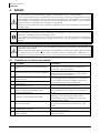
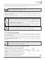
6.4
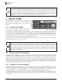
« ERROR » INDICATOR (3)
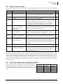
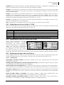
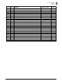
The table hereunder describes the type of error according to the number of times this indicator
flashes.
Indic. Indicated error
Comment
No.
Off
No problem
If no indicator lights up, the equipment is de-energized. 01
On
The equipment is OFF
The equipment is energized but it does not operate
02
because of a user command (the “Set” button has
been pressed for 5s).
Flashes Battery low voltage
The equipment is still operating but shows that the
03
1x
warning
battery is lower than 10/20/40V.
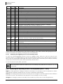
Flashes Earth fault
The VarioTrack detects an abnormal situation which
04
2x
does not correspond to the programmed value of the
parameter {10060} checking the state of the earth
connection. The VarioTrack turns off. It automatically
starts again when the normal situation is restored.
Flashes Power reduction or stop
This may be due to an excessive ambient temperature, 05
3x
due to an excessive
exposure of the equipment to a heat source (sun) or to
temperature in the
deficient or impeded ventilation.
equipment.
Flashes Battery voltage higher
Check the cause of this excessive voltage. The
06
4x
than 17/34/68V
equipment automatically starts again when voltage
returns to a value lower than 17/34/68V.
Flashes The PV voltage is higher
The PV voltage exceeds the max limit of 145V (75V
07
5x
than the set value of the
when battery is 12V). The equipment will stop or won’t
max operating limit.
start.
Flashes
The PV generator is probably disconnected. Check the 08
No voltage has been
6x
protection devices (fuse or circuit breaker) and/or
detected for 48h.
check the wiring. As a last resort, after making sure that
the PV generator is disconnected, check the internal
fuse (5)*
Flashes Battery fault
Missing battery, polarity reversal or voltage lower than
09
7x
7V.
Flashes Software incompatibility in The different parts of the system’s equipment must
10
8x
a multi-inverter system.
have the same software version to function properly.
Proceed with the update following the procedure in
manual RCC-02/-03.
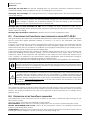
* If the internal fuse is broken, this shows a major error in your wiring: most probably either a short
circuit on the generator side, either a reverse connection of the battery on the solar input! In such
case, check carefully the operation of the equipment after the error has been corrected. The fuse is
composed of 4 fuse links 30A/80V that must be replaced by fuses of exactly the same type, i.e.: ref.
Littlefuse: FKS 166.7000.530 or equivalent. This operation must be carried out by qualified personnel.
In case of doubt, the equipment must be returned to the supplier for a check (this fault is not covered
by the warranty).
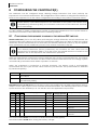
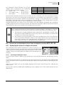
6.5
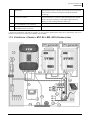
CHARGING CURRENT INDICATOR (5)-(6)-(7)-(8)
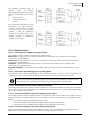
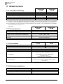
These indicators flash or light up continuously to indicate
the current charging range as per the table hereafter.
The RCC-02/03 remote control allows a complete and
detailed display of the VarioTrack behaviour (see. chap.
9.1).
Manuel utilisateur
V 3.0.0
Flashing
indicator
60-70A
40-50A
20-30A
0-10A
Indicator
number
LED (8)
LED (7)
LED (6)
LED (5)
Lit up
indicator
70-80A
50-60A
30-40A
10-20A
21