1
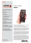
User Manual JOFRA STS-102 A Sensor 030 Copyright 2002 AMETEK DENMARK A/S 2 28-01-2005 123829 02 List of contents 1.0 2.0 3.0 4.0 General information .................................................................4 Safety instructions ...................................................................5 Introduction ..............................................................................6 Functionality .............................................................................7 4.1 Functional description................................................................... 7 4.2 Connections .................................................................................. 7 4.3 Serial number ............................................................................... 8 5.0 Operation ..................................................................................9 5.1 Operation area.............................................................................. 9 6.0 7.0 8.0 Maintenance............................................................................10 Technical specifications - sensor.........................................11 Calibration of temperature sensors for sanitary process connection ..............................................................................13 8.1 8.2 8.3 8.4 Accessories kit............................................................................ 13 The reference sensor.................................................................. 14 The calibration sequence ........................................................... 16 Drilling instructions...................................................................... 17 123829 02 28-01-2005 3 1.0 General information This manual is only effective for the following product: • JOFRA STS-102 A 30 mm The product is manufactured by: AMETEK DENMARK A/S GYDEVANG 32-34 DK-3450 ALLERØD DENMARK TEL: +45 48 16 80 00 FAX: +45 48 16 80 80 4 28-01-2005 123829 02 2.0 Safety instructions Read this manual carefully before using the sensor! In order to avoid any personal injuries and/or damage to the sensor all safety instructions and warnings must be observed. Warning • • • Do not use in hazardous area. Handle carefully. Never exceed temperature range Caution… • • • • When measuring temperature in fluids (e.g. at recalibration) the enclosed protection tube must be used. The sensor must always be protected against any mechanical damage. The sensor must never be exposed to mechanical shock effects. Avoid thermal shock • Any bending of the sensor may cause permanent damage • Never use power or tools to place the sensor. 123829 02 28-01-2005 5 3.0 Introduction The JOFRA STS-102 A 030 sensor is designed for fast and traceable calibration and temperature measuring with AMETEK DTIand ATC-systems, and is ready for use. The JOFRA STS-102 A 030 sensor is through its functional design adapted for calibration of short sensors in dry-block calibrators. Please read this manual carefully before use, to obtain maximum value of your calibration system. Warning • • • 6 Do not use in hazardous area. Handle carefully. Never exceed temperature range 28-01-2005 123829 02 4.0 Functionality 4.1 Functional description The sensor can be used for measuring temperature in the range -50°C to 155°C (-58°F to 311°F). The sensor is designed for measuring temperature in a dry-block calibrator. Caution… When measuring temperature in fluids (e.g. at re-calibration) the enclosed protection tube must be used. Sensors may be supplied with certificates for a limited temperature range. 4.2 Connections The sensor is delivered with a connecting cable and with the following options: Model with lemo connection: 123829 02 1 metre cable 28-01-2005 7 4.3 Serial number The serial number is placed on the connector as shown on the photo below: 8 28-01-2005 123829 02 5.0 Operation 5.1 Operation area All the sensors are intended for use in areas which meet the following: Ambient temperature range Humidity : : 0°C to 50°C (32°F to 122°F) 0% to 90% Protection class : IP 50 Warning • 123829 02 Do not use in hazardous areas. 28-01-2005 9 6.0 Maintenance The sensor does not require specific maintenance before or after use. The user may carry out the following procedure himself: Cleaning sensor : Use alcohol or water and a soft cloth. Caution… • • • • 10 The sensor must always be protected against any mechanical damage. The sensor must never be exposed to mechanical shock effects. Avoid thermal shock Any bending of the sensor may cause permanent damage 28-01-2005 123829 02 7.0 Technical specifications - sensor Sensor type : 4 wire Pt100. α100 = 0.00385 1/ °C Sensor length : 30 mm / 1.8 inch. Temperature range : -50°C to 155°C (-58°F to 311°F) Hysteresis @0°C / 32°F : 1) ±0.01°C / 0.018°F Stability @0°C / 32°F : typ. 0.025°C / 0.045°F Repeatability : 0.002°C / 0.0036°F Diameter : OD4 mm Immersion depth : Min. 30 mm / 1.8 inch. Media compatibility : AISI 316 TI Response time : τ0.9 = 16 sec. (measured in water) Self-heating effect : 0.06°C / mW / 0.108°F / mW Recommended meas. current : 1 mA Connections : Lemo plugs are standard Insulation resistance @23°C / 73°F : 3 Gohm 1) when exposed to 155°C (311°F) for 200 hours. Stability will depend on actual use of the sensor. Certificate: Upon request all sensors can be supplied with an accredited certificate according to the ITS 90 temperature scale. The sensors are as standard calibrated in the range –45°C to 155°C (-49°F to 311°F). 123829 02 28-01-2005 11 Calibration is carried out at: • • • • • • 12 -45°C/-49°F -20°C/-4°F 0°C/32°F 50°C/122°F 100°C/202°F 155°C/311°F 28-01-2005 123829 02 8.0 Calibration of temperature sensors for sanitary process connection 8.1 Accessories kit Instructions for accessories kit for calibration of sanitary sensors: The accessories kit, Part No. 123859 contains the following parts: • • • • • • 1 pcs. carrying case for safe storing of accessories 5 pcs. undrilled insertion tubes 1 pcs. reference sensor with cable. Temperature range –50 to 155 °C 1 pcs. accredited certificate 1 pcs. user manual 1 pcs. protection tube This kit can only be used with the ATC-156, A or B version. When calibrating sanitary sensors or sensors with short insertion lengths in general various conditions have to be considered to obtain an optimum and correct calibration. Therefore, AMETEK Denmark A/S recommends that this instruction be followed. 123829 02 28-01-2005 13 A sanitary sensor is normally similar to one of the two examples shown below. insertion length Flange Fig. 1 Due to the very short insertion length, heat transfer through the sensor tube and flange is of great importance to the calibration result. Therefore, it is very important to achieve a good thermal contact to the sensor as well as to the flange. Make sure that the sensor fits exactly into the supplied insertion tube. It is very important to have good mechanical and thereby also thermal contact between the flange and the horizontal surface of the insertion tube. In other words, there must be no air between the flange and the insertion tube. (See also fig. 2). 8.2 The reference sensor Included in the package is a reference sensor especially developed for the purpose. It is important that this reference sensor is treated careful so it does not suffer any harm. When placing the reference sensor in the reference hole of the insert (Ø 4.2 mm) make sure that there is no mechanical resistance. 14 28-01-2005 123829 02 Caution… Never use power or tools to place the sensor. When the calibration is over, the reference sensor should be removed from the insert and stored in an appropriate place, for example in the carrying case included in the delivery. Note… We recommend recalibrating the reference sensor at least once a year, more if there is any doubt about its measuring capability. The reference sensor may be calibrated as an independent unit or as a system together with the calibrator. Sensor-under-test 0 mm Reference sensor Reference obe Insert Reference level for reference sensor as well as for sensor-under-test Fig. 2 123829 02 28-01-2005 15 8.3 The calibration sequence 1. Place the special insert in the calibrator. 2. Place the reference sensor in the reference hole of the special insert. Make sure that the reference sensor reaches down to the bottom. The cable is placed in the groove of the insert. If the calibrator’s reference input is used, make sure that the correct calibration data for the reference sensor have been downloaded, see user manual 105447 for ATC-156B. If another reference instrument is used, please follow the instructions for this. 3. Place the sanitary sensor in the insert and make sure that the cable of the reference sensor is not jammed, but completely free. 4. When calibrating it is a good idea to try to create a calibration situation as close to reality as possible. 5. If the sensor is normally insulated in the process, it should also be insulated in a similar way during the calibration to secure the same thermal conditions. (See fig. 3). Fig. 3 16 28-01-2005 123829 02 6. Calibration and setup of the calibrator as usual and as described in the user manual. Please note that all temperature points and the accuracy during the calibration must relate to the reference sensor and not to the “Read” value in the display. To avoid discrepancies between “Set” value and “Read” and “True” values it is recommended to use the “Set Follows True” function as described in the user manual 105447 for the ATC calibrator. If using this function, calculate on a prolonged calibration time of approx. 10 minutes per calibration point. 8.4 Drilling instructions In order to obtain good measuring results it is important that the hole of the insert fits exactly into the dimensions of the sensor tube to ensure a good contact between the sensor and the insert. It is especially important that the flange of the sensor fits tight to the surface of the insert. Procedure: 1. The part of the sensor that must be dropped down into the insert is measured. The diameter “d” and the length “l” must be measured. If the sensor has different diameters, all of these must be measured as well as their corresponding lengths. It is important to note that there where the change in the sensor’s diameter occurs, the transition is gradual in an arched form (“r1” and “r2”). 2. The hole for the sensor is placed in the centre of the insert. The diameter is stated as the measured diameter + 0.2 mm. The tolerance of the diameter must be ±0.05 as indicated in fig. 4. 3. The length of the hole for the sensor is the measured length + 0.5 mm. 4. The hole for the reference sensor must be similar to the total length of the sensor “l1”, see fig. 4. The diameter of the hole for the reference sensor is 4.2 mm as indicated in fig. 4. 123829 02 28-01-2005 17 5. The hole for the reference sensor is placed in the drilling. There need to be 3 mm between the diameter of the reference sensor and the largest diameter of the sensor-under-test. A A A-A (1:1) Fig. 4 18 28-01-2005 123829 02