1
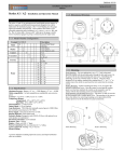
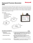
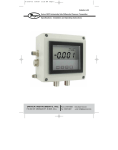
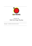
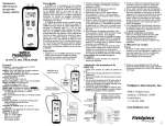
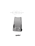
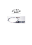
Bulletin 102-0 Installation and Operation Manual Series A3 and A4 Differential Pressure Controller Sensocon, Inc. Phone: (863) 248-2800 Fax: (863) 248-2798 www.sensocon.com Installation and Operation Manual Series A3 & A4 Contents 1. 2. 3. 4. 5. Introduction 1.1. Model Number Configuration 1.2. Specifications 1.3. Dimensional Drawings Installation 2.1. Mounting 2.2. Pressure Connections 2.3. Electrical Connections Operation 3.1. Display 3.2. Key Function Programming 4.1. Menu Structure 4.2. Security Level 4.3. Main Menu 4.4. Set-Up Menu 4.5. Secure Menu Other Features 5.1. Moving Program Variables 5.2. Opti-Link 5.3. Limited Warranty (863) 248-2800 www.sensocon.com 2 Installation and Operation Manual Series A3 & A4 1. INTRODUCTION The Sensocon A3 and A4 series of differential pressure controllers provide control of low differential pressure applications for air and other compatible non combustible gasses. These instruments have a large LED display for pressure indication, a LCD or OLED display for programming and additional LED’s to indicate % of output, setpoints and alarm status. The instruments are fully programmable from the key pad face or by utilizing the Opti-Link™ communication port for no touch programming. Options for the instruments include a 4-20 mA output, and improved accuracies. There is also a low cost weatherproof cover available for outdoor applications. 1.1 Model Number Configuration Example Model Display Control Transmitter Accuracy Range A3110-06 A 3 4 1 0 1 0 1 - 01 02 03 04 05 06 07 08 09 10 11 Description Round Panel Mount Housing LED display, process arch, LCD LED display, process arch, OLED Control 2 SPDT relays None 4-20 mA 1% 0.50% 0 – 0.50” 0 – 1” 0 – 2” 0 – 3” 0 – 4” 0 – 5” 0 – 8” 0 – 10” 0 – 15” 0 – 20” 0 – 30” 1.2 Specifications Maximum Pressure: Ranges ≤ 4” w.c. = 2 PSI; Ranges ≥ 5” w.c. = 10 PSI Media compatibility: Air and compatible non combustible, non corrosive gasses Accuracy*: Axxx0-xx - 1.00%; Axxx1-xx - 0.50% Temperature Ranges: Compensated: -10° to 140°F (-23° to 60°C) Operating: -10° to 140°F (-23° to 60°C); A3: 10° to 140°F (-12° to 60°C) Thermal Effect*: +/- 0.012% FS/°F Output Signal: 4-20 mA (option) (863) 248-2800 www.sensocon.com 3 Installation and Operation Manual Series A3 & A4 Loop Resistance: 750 Ω Max (for internally sourced power); 1800 Ω Max (for externally sourced power of 36 VDC) Power Supply: Universal 16-265 VAC or VDC Housing Material: Glass Filled Nylon Enclosure Rating: Designed to meet NEMA 4X face; with optional cover the entire product is weatherproof Relays: (2) SPDT 8 Amps @ 250 VAC, 5A @30 VDC Electrical Connections: screw terminals Response Time: <100 ms Display: 4 Digit, red LED, ½” digits; LCD or OLED programming display Process Connection: Push on connection for 3/16” tubing Agency Approvals: Pending – UL, C-UL, CE Patents Pending * Custom calibrations including improved accuracy and improved thermal effect are available. 1.3 Dimensional Drawings Series A3 and A4 Series A3 and A4 with optional weatherproof cover (863) 248-2800 www.sensocon.com 4 Installation and Operation Manual Series A3 & A4 Optional weatherproof cover 2. INSTALLATION 2.1 Mounting Flush Mounting – For new applications, cut a 4 9/16” hole in the panel. Insert the control with the provided gasket through the hole and secure it to the panel with the provided mounting tabs and screws. Retrofitting old technology is also easy with the Series A3 and A4. They have been designed to fit in industry standard holes ranging from 4 9/16” to 4 13/16” so simply remove the old device and insert the new control into the existing cut out. (863) 248-2800 www.sensocon.com 5 Installation and Operation Manual Series A3 & A4 Surface Mounting – Surface mounting the Series A3 or A4 requires the optional weather proof cover. Once the control is wired and the weather proof cover has been attached, the control can be mounted to any flat surface with the four mounting screws provided with the cover. Flush Mounting with Weather Proof cover – The Series A3 and A4 can also be flush mounted with a weather proof cover. The procedure is the same as above, but utilizes two extra long mounting screws (provided with the weather proof cover) for the bottom two panel connections. (863) 248-2800 www.sensocon.com 6 Installation and Operation Manual Series A3 & A4 2.2 Pressure Connections Two 3/16” pressure connections are located on the back of the unit, labeled “High” and “Low”. For best results, connect 3/16” I.D. push on tubing to the pressure connections. If the High connection has a greater absolute value than the Low connection, the front display will give a positive value. If the HI connection has a lower absolute value than the LO connection, the front display will give a negative value. 2.3 Electrical Connections NOTES: 1. Supply Voltage is universal from 16-265VAC or VDC 2. For internally sourced 4-20 mA loop, maximum loop resistance is 750 Ω; for externally sourced loop at 36 VDC, maximum loop resistance is 1800 Ω. 3. Isolation: Relays: 1000 VAC to all other inputs and outputs 4-20 mA: 5000 VAC to all other inputs and outputs. (863) 248-2800 www.sensocon.com 7 Installation and Operation Manual Series A3 & A4 3. OPERATION 3.1 Display The series A3 and A4 were designed to give the user maximum feedback and flexibility. The process arch LED’s are designed to mimic the indicating needle of a mechanical gauge. The process arch will light up from left to right as the pressure moves away from zero. Negative pressure will be indicated by the negative sign before the numerical indication. The 4 digit LED displays the numerical pressure reading and will show either 3 or 4 digits based on the users preference. The LCD (or OLED) display is used for programming and displaying the unit of measure and up to 4 other user selected program parameters. The LED indicators for SP1, SP2, and Alarm give indication when the parameter is in the actuated state. Setpoint and Alarm Indicators Negative Indication Process Arch LED Pressure Indication LCD or OLED Programming Display 3.2 Key Function The A3 and A4 have four buttons located on the face of the control used for programming. There is an up arrow, a down arrow, a left arrow/cancel, and a right arrow/accept button as shown below. up arrow (863) 248-2800 down arrow left arrow / cancel www.sensocon.com right arrow / accept 8 Installation and Operation Manual Series A3 & A4 To move from one program menu to another, hold the up arrow or down arrow for one second to move up or down one menu level. The control will start in the “Main” menu, one level up is the “Set-up” menu, and one more level up is the “Secure” menu. The up and down arrows are used to navigate up and down through the parameters in each menu. To change a parameter, use the up and down arrows until the parameter is highlighted, then press the right arrow. This will advance you to another screen where you can change the parameter. There are two different types of parameter change screens, 1) you select a given option or 2) you change a numerical value. To change a number, the left and right arrows are used to select the digit you would like to change, the up and down arrow will increase or decrease the value by the amount selected. Once you have made the change, you can accept the change by holding the accept button for three seconds, this will accept the change and take you back to the menu you were currently in. At any point while in a parameter change screen, you can hold the cancel button for one second to return to the previous menu without accepting a change to that parameter. To manually reset the alarm after an alarm condition has occurred (if this feature is used) hold the right and left arrows simultaneously until the alarm resets. 4. PROGRAMMING 4.1 Menu Structure The factory default menu structure for all of the available variables is shown in the below table. Based on the user selections in the Set-up Menu, some of the variables may not be visible. It is also possible to change the menu structure by moving variables from one menu to another (see Moving Program Variables). Menu Variable Set Point 1 Low Set Point 1 High Set Point 1 Set Point 1 db Set Point 2 Low Set Point 2 High Set Point 2 Set Point 2 db Alarm Low Alarm High Main Menu Set-up Menu Control Set Point 1 Setting (863) 248-2800 Code SP1 lo SP1 hi SP1 SP1 db SP2 lo SP2 hi SP2 SP2 db AL lo AL hi Setting value value value value value value value value value value Ctrl Set 1 1 SP / 2 SP / SPAL / AL db / lohi www.sensocon.com 9 Installation and Operation Manual Secure Menu Series A3 & A4 Actuation 1 Set Point 1 Delay Set Point 2 Setting Actuation 2 Set Point 2 Delay Alarm Alarm Reset Alarm Inhibit Alarm Delay Peak Valley Mode Units 1 act SP1 D Set 2 2 act SP2 D AL AL Rs AL ih AL D Peak Valy Mode Units Resolution Display Dampening Screen Saver Contrast Res Dis Damp Saver Contr K Factor Duct Shape Duct Diameter Duct Width Duct Height Kfact Xsect diam X dim Y dim Zero Span Access Zero Span Access Reset pol poh P/S Reset value - Reset Main / Set-up / Secure / none No / Yes value value Off / On Factory Default Process Output Lo Process Output Hi Current Power source dir / rev value db / lohi dir / rev value lo / hi / hilo Manual / Auto Off / On value value value Pres / Vel / Flow inWc / mmWc / cmWc / Pa / kPa / PSI / inHg / mmHg / mBAR / ftWc / oz in / SFPM / M/S / SCFM / M3/S 3 dig / 4 dig std / pct value Off / On N-lo / N-med / N-hi / I-lo / I-med / I-hi value circ / rect value value value 4.2 Main Menu The parameters shown in the Main Menu will be dictated by the Control type selected in the Set-Up Menu. The parameters in the Main Menu will also be displayed on the LCD during normal operation if Screen Saver is set to Off. The value chosen for each set point will determine the switch point for that respective (863) 248-2800 www.sensocon.com 10 Installation and Operation Manual Series A3 & A4 variable. Below are the possible parameters that would be shown with the factory default program. Set Point 1 Low (SP1 lo) Set Point 1 High (SP1 hi) Set Point 1 (SP1) Set Point 1 Deadband (SP1 db) Set Point 2 Low (SP2 lo) Set Point 2 High (SP2 hi) Set Point 2 (SP2) Set Point 2 Deadband (SP2 db) Alarm Low (AL lo) Alarm High (AL hi) * To change the displayed parameters on the LCD during normal operation, see Moving Program Variables (section 5.1). 4.3 Set-Up Menu Control (Ctrl) – Selection of the control type will determine which parameters are or are not available in the remainder of the Set-up Menu as well as the Main Menu. Example: If 1 Set Point is selected, there will be no parameters for Set Point 2 or Alarm in the programming. 1 Set Point (1SP) – For control with one SPDT relay 2 Set Point (2SP) – For control with two independent SPDT relays Set Point Alarm (SPAL) – For control with one SPDT relay and one alarm relay Alarm (AL) – For alarm operation only Set Point Settings (Set 1 & Set 2) – Each set point can be entered as a high and low value for the turn on and off point or as an set point and a floating dead band. Low High operation is best suited for applications that have a set turn on and turn off point. Set Point Deadband is suited for application that may require changing the set point from time to time but the deadband will always remain the same. The below graphs illustrate the differences. Low High (lohi) – For a high and low set point Set Point Deadband (SP db) – For a set point and floating dead band (863) 248-2800 www.sensocon.com 11 Installation and Operation Manual Series A3 & A4 HiLo Operation Pressure Set Point Hi Set Point Lo Time Relay Action Direct Acting Reverse Acting OFF ON OFF ON OFF ON Setpoint DB Operation Pressure DB direct acting DB reverse acting Set Point Time Relay Action Direct Acting Reverse Acting OFF ON ON OFF OFF ON Actuation (1 act & 2 act) – The actuation parameter determines whether the relays will react to increasing or decreasing pressure. This parameter also affects the status of the LED indicators on the front of the gauge. The above graphs illustrate the differences. Direct – The relays turn on with increasing pressure Reverse – The relays turn on with decreasing pressure (863) 248-2800 www.sensocon.com 12 Installation and Operation Manual Series A3 & A4 Set Point Delay (SP1 D & SP2 D) – This variable sets the minimum amount of time that the process must be above or below the set point for the switch state to actuate. value – Time in seconds Alarm (AL) – There are three different alarm types that can be selected, high alarm, low alarm, or high and low alarm. The high alarm will actuate the relay when the process is above the high alarm set point. The low alarm will actuate the relay when the process is below the low alarm set point. The high and low alarm can be used together so the alarm relay is actuated when the process is above or below the high alarm and low alarm set points respectively. The selection will dictate which alarm parameters are shown in the Main Menu. The below figure shows the three alarm types. High Alarm (hi) – High alarm Low Alarm (lo) – Low alarm High Low Alarm (hilo) – High and low alarm Hi Alarm OFF - FS ON 0 + FS Pressure Lo Alarm ON OFF - FS 0 + FS Pressure Lo Alarm ON - FS Hi Alarm OFF 0 ON + FS Pressure Alarm Reset (AL Rs) – In the case of an alarm condition, the control can be configured to automatically reset when the alarm condition goes away or to (863) 248-2800 www.sensocon.com 13 Installation and Operation Manual Series A3 & A4 require a manual reset by holding the left arrow and right arrow simultaneously on the face of the control. Automatic (Auto) – For automatic reset Manual (Manual) – For manual reset Alarm Inhibit (AL ih) – This parameter allows the user to suspend the alarm during power up until the process moves through the low alarm set point. If alarm inhibit is off, and the control is in an alarm condition at power up it will alarm and possibly require manual reset. On (On) – Alarm Inhibit is on Off (Off) – Alarm Inhibit is off Alarm Delay (AL D) – This variable sets the minimum amount of time that the process must be above or below the alarm before the switch state alarms. value – Time in seconds Peak (Peak) – The peak is the highest value the control has reached since the last time it was reset. value – Allow the user to manually reset the value. Valley (Valy) – The valley is the lowest value the control has reached since the last time it was reset. value – Allows the user to manually reset the value. Mode (Mode) – The control is capable of measuring and displaying pressure, velocity, or flow. For velocity and flow, a flow sensing device such as a pitot tube, or orifice plate with a know flow coefficient is required. For flow, it is also necessary to know the dimensions of the duct that the flow is being measured in so the control can calculate the area. Pressure (Pres) – To display and control pressure Velocity (Vel) – To display and control velocity Flow (Flow) – To display and control flow Units (Units) – The engineering units selected will be displayed on the LCD during programming and normal operation of the control. The unit of measure selected will be used for displaying the pressure, velocity or flow reading as well as all programming variables. If the units are changed after programming has occurred, all values will automatically be changed to the correct corresponding value of the new unit of measure. The unit conversion equivalents are shown in the below table. Pressure (inWc) – Inches of water column (mmWc) – Millimeters of water column (cmWc) – Centimeters of water column (Pa) – Pascals (863) 248-2800 www.sensocon.com 14 Installation and Operation Manual Series A3 & A4 (kPa) – Kilopascals (PSI) – Pounds per square inch (inHg) – Inches of mercury (mmHg) – Millimeters of mercury (mBAR) – Millibars (ftWc) – Feet of water column (oz in) – Ounce inches Velocity* ** (SFPM) – Standard feet per minute (M/S) – Meters per second Flow* ** (SCFM) – Standard cubic feet per minute (M3/S) – Cubic meters per second *The displayed reading is based on standard conditions – dry air at 70° F and a barometric pressure of 29.92 inches of mercury. **The control will automatically switch to x10 or x100 for velocity or flow when the reading exceeds four digits. This will be indicated on the LED by alternating the flow or velocity reading with the “α10” or “α100” symbol. The maximum displayed velocity or flow will be 9999 x100 regardless of units. Maximum Displayed Pressures inWc 0.250 0.500 1.000 2.000 3.000 4.000 5.000 8.000 10.00 15.00 20.00 30.00 ftWc 0.021 0.042 0.083 0.167 0.250 0.333 0.417 0.667 0.833 1.250 1.667 2.500 mmWc 6.350 12.70 25.40 50.80 76.20 101.6 127.0 203.2 254.0 381.0 508.0 762.0 cmWc 0.635 1.270 2.540 5.080 7.620 10.16 12.70 20.32 25.40 38.10 50.80 76.20 PSI 0.009 0.018 0.036 0.072 0.108 0.145 0.181 0.289 0.361 0.542 0.723 1.084 inHg 0.018 0.037 0.074 0.147 0.221 0.294 0.368 0.588 0.736 1.103 1.471 2.207 mmHg mBAR 0.467 0.623 0.934 1.245 1.868 2.491 3.737 4.982 5.605 7.473 7.473 9.964 9.342 12.45 14.95 19.93 18.68 24.91 28.02 37.36 37.37 49.82 56.05 74.73 Pa 62.27 124.5 249.1 498.2 747.3 996.4 1245 1993 2491 3736 4982 7473 kPa 0.062 0.125 0.249 0.498 0.747 0.996 1.245 1.993 2.491 3.736 4.982 7.473 oz in 0.145 0.289 0.578 1.156 1.734 2.312 2.890 4.624 5.780 8.671 11.56 17.34 Resolution (Res) – The pressure reading on the LED display can be shown with 3 or 4 digits. In some cases, the fourth digit is outside of the accuracy of the product and insignificant. If the fourth digit is used and is insignificant, there may be fluctuations in that digit. 3 Digit (3 dig) – 3 digit display 4 Digit (4 dig) – 4 digit display Display (Dis) – In addition to the selectable units for pressure, velocity, and flow, the display can also be configured to read as a percent output. Standard (std) – Displays selected engineering unit Percent (pct) – Displays 0-100% instead of the selected engineering unit (863) 248-2800 www.sensocon.com 15 Installation and Operation Manual Series A3 & A4 Dampening (Damp) – The control takes a pressure sample every 100 milliseconds. The dampening coefficient tells the control how many readings to average for the displayed value. Displaying readings with too few samples averaged may cause unstable readings as a result of vibration or pressure fluctuations. value – Number of samples averaged for the displayed value Screen Saver (Saver) – When the control is in normal operation the screen saver displays only the units of measure on the LCD or OLED display. When the screen saver is in use, touching any button on the face of the control will display the main menu. If turned off, the programming screen will display the parameters in the main menu. Off (Off) – Turns the screen saver function off On (On) – Turns the screen saver function on WARNING: NOT USING THE SCREEN SAVER WITH THE SERIES A4 MAY CAUSE THE OLED DISPLAY TO BURN IN. Contrast (Contr) – This allows the image and contrast of the programming display to be adjusted. Normal low (N-lo) – Normal image, low contrast Normal medium (N-med) – Normal image, medium contrast Normal high (N-hi) – Normal image, high contrast Inverted low (I-lo) – Inverted image, low contrast Inverted medium (I-med) – Inverted image, medium contrast Inverted high (I-hi) – Inverted image, high contrast K Factor (Kfact) – For flow and velocity, it is necessary to enter the flow coefficient of the flow sensing device you are using (pitot tube, orifice plate, etc.). This value should be specified by the manufacturer of the device. value – coefficient (0.01 to 99.99) Duct Shape (Xsect) – For flow measurement, it is necessary to calculate the area of the duct where the measurement is being taken. The first step is to determine the shape of the duct. Rectangle (rect) – For a rectangular or square duct Circle (circ) – For a circular duct Duct Diameter (diam) – For circular ducts, enter the diameter for the area calculation. value – Diameter in inches (or meters) Duct Width & Height (X dim, Y dim) – For rectangular ducts, enter the width and height for the area calculation. value – Height and width in inches (or meters) (863) 248-2800 www.sensocon.com 16 Installation and Operation Manual Series A3 & A4 4.4 Secure Menu Zero (Zero) – This is a calibration parameter that allows re-calibration of zero. To re-zero the control, disconnect both pressure connections so they are open to atmospheric pressure and reset the value by holding the accept key. Cancel (Cancel) – This cancels the zero operation Reset (Reset) – This will reset the zero point of the control Zero pressure must be maintained during the zero operation. Span (Span) – This is a calibration parameter that allows re-calibration of the span. To re-span the control, first enter the full scale pressure value you will be calibrating to, then apply that pressure to the high pressure port and reset the value by holding the accept key. value / Accept – This will reset the span of the control The pressure must be maintained at the set value during the span operation. Security Access (Access) – This parameter allows you to prevent users from accessing menus to prevent tampering. Once this parameter is set, a security code must be entered to regain access to the locked menus as shown in the below table. This feature can be used in conjunction with “moving program variables” (section 5.1) to grant or restrict access to specific variables. Secure menu (Secure) – Selecting Secure will give the user access to all menus. Set-up menu (Set-up) – Selecting Set-Up will give the user access to the Main menu and the Set-up menu. Main menu (Main) – Selecting Main will allow access only to the main menu. No menus (none) – Selecting none will allow the user to view parameters only in the main menu, but they will not be able to make any changes. Security Code Table Menu Security Code Main 2312 Set-up* 4534 Secure** 6756 * Entering the security code for Set-up will also give access to Main ** Entering the security code for Secure will give access to all Menus Factory Default (Reset) – By performing a Factory Default, the control will be configured back to the original factory settings. This includes set values and menu structure. Cancel (Cancel) – This cancels the factory default Reset (Reset) – This accepts the factory default and resets the control (863) 248-2800 www.sensocon.com 17 Installation and Operation Manual Series A3 & A4 Process Output Low (pol) – This parameter allows the 4-20 mA output to be scaled. The value set for this parameter will correspond to the 4 mA output. The default setting will be 0, but can be set at any value lower than Output High. value – The pressure that corresponds to the 4 mA output signal Process Output High (poh) – This parameter allows the 4-20 mA output to be scaled. The value set for this parameter will correspond to the 20 mA output. The default setting will be the full scale pressure reading of the control, but can be set at any value higher than Output Low. value – The pressure that corresponds to the 20 mA output signal Current Power Source (P/S) – This parameter allows the power for the 4-20 mA loop to be sourced internally by the control or externally. On (On) – Power will be sourced by the control Off (Off) – External power will be required for the current loop 5. OTHER FEATURES 5.1 Moving Program Variables The programming menu can be fully customized by the user. Parameters can be moved from one menu to another. This allows the user to reorganize the menu structure to better fit their needs or to put unused or unwanted parameters in one menu and then lock that menu so that those variables can not be accessed. To move a program parameter to another menu, highlight the parameter to be moved and hold down the left arrow for one second and the following screen will appear: New Menu Main – Moves the parameter to the Main menu Setup – Moves the parameter to the Set-up menu Secure – Moves the parameter to the Secure menu Select the menu you would like the parameter to be moved to and press accept. 5.2 OptiLink™ Optilink™ is an infrared communications technology that allows the user to upload and download program parameters from one unit to another with a programming key. By using the PK-01 universal programming key, the user may program one unit, download those parameters to the universal programming key and then upload that same program from the key to other controls. By using a (863) 248-2800 www.sensocon.com 18 Installation and Operation Manual Series A3 & A4 PK-02 lockout programming key, a user may completely lock (or unlock) the face keypad of the control to eliminate the possibility of unwanted tampering of the control. To download programs from a control to a programming key, place the key within 1 to 6 inches of the OptiLink™ port on the control and hold the two outside buttons simultaneously until the numeric LED on the control turns off. The programming key must stay within the 1 to 6 inch range while the download is in progress. During the operation, the Process Arch on the control will give the status of the download. When the download is complete, the programming key will blink green twice to indicate the program is stored on the programming key. To upload programs from a programming key to a control, place the key within 1 to 6 inches of the OptiLink™ port on the control and hold the center button until the numeric LED on the control turns off. The programming key must stay within the 1 to 6 inch range while the download is in progress. During the operation, the Process Arch on the control will give the status of the download. When the upload is complete, the control will read “yes” to indicate the program has been successfully uploaded to the control. 5.3 Limited Warranty LIMITED WARRANTY SENSOCON warrants its products to be free from defects in materials and workmanship for a period of one (1) year from the date of shipment, subject to the following terms and conditions: Without charge, SENSOCON will repair, replace, or refund the purchase price at SENSOCON’s option products found to be defective in materials or workmanship within the warranty period; provided that: i. the product has not been subjected to abuse, neglect, accident, incorrect wiring not our own, improper installation or servicing, or use in violation of labels or instructions provided by SENSOCON; ii. the product has not been repaired or altered by anyone except SENSOCON; iii. the maximum ratings label and serial number or date code have not been removed, defaced, or otherwise changed; iv. examination discloses, in the judgment of SENSOCON, the defect in materials or workmanship developed under normal installation, use and service; and v. SENSOCON is notified in advance of and the product is returned to SENSOCON transportation prepaid before expiration of the warranty period. THIS EXPRESS LIMITED WARRANTY IS IN LIEU OF AND EXCLUDES ALL OTHER REPRESENTATIONS MADE BY ADVERTISEMENTS OR BY AGENTS AND ALL OTHER WARRANTIES, BOTH EXPRESS AND IMPLIED. THERE ARE NO IMPLIED WARRANTIES OF MERCHANTABLILTY OR OF FITNESS FOR A PARTICULAR PURPOSE FOR GOODS COVERED HEREUNDER. (863) 248-2800 www.sensocon.com 19 Installation and Operation Manual (863) 248-2800 www.sensocon.com Series A3 & A4 20