1
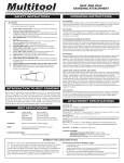
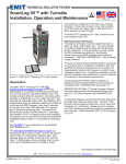
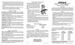
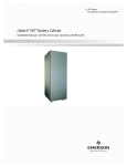
P.O. Box 930219 | Verona, WI 53593-0219 | 1-800-383-5547
MODEL 6000 BELT GRINDER P
24 Tool Tray
25 Tool Tray Bracket
Red Emergency
Stop Button
20 •21
Spring
•6 11 22
13
12
14
ON/OFF
Button 19
16
Belt
Alignment Knob 9
18
Graphite
Plate
17
10 •6
•5
4
3
15
3
1
7
• Do not loosen or remove
items 5 or 6 unless to
replace items 2, 3, or 4.
• Knob 11, see belt
change instructions
on page 4.
2
8
2
27
Coil and
Receptacle Box
23
Top Cover,
Hinge is welded
to cover assembly.
ARTS LIST AND ILLUSTRATION
MODEL 6000 BELT GRINDER
ITEM
No.
PART
No.
1
2
3
4
4655
7017
4506
7016
5
4162
6
7
8
9
10
11
4339
7004
4022
7027
7009
7026
12
7007
13
7008
DESCRIPTION
Contact Wheel
Spindle
Ball Bearing
Bearing Housing
Sock. Hd Cap Screw,
3/8-16 x 3/4
Lock Washer
Stand — Welded Assy.
Hex. Head Bolt, 3/8-16 x 3/4
Belt Alignment Knob
Sliding Tube — Welded Assy.
Belt Release Handle
Mounting Plate and
Tube-Welded Assy.
Motor Assy.
ITEM
No.
PART
No.
14
15
7003
7034
16
4972
17
18
19
7035
7037
4807
20
4809
21
22
23
24
25
26
27
7070
7050
7051
7091
7092
7100
4776
DESCRIPTION
Cover Assy.
Drive Pulley
Abrasive Belts, 2½ x 60,
Grits 36-220
Belt Release Lever Assy.
Graphite Plate
On-Off Button
Red Emergency
Stop Button
Adapter Bolt
Spring
Top Cover
Tool Tray
Tool Tray Bracket
Wheel Assy.
Coil Box
26
3
INSTALLATION & OPER
CAUTION:
DISCONNECT POWER SUPPLY CORD FROM POWER
SOURCE WHEN DOING REPAIR WORK ON THE MACHINE.
INSTALLATION
SAFETY PRECAUTIONS
First, check machine over for any shipping damage. After
the belt grinder is uncrated, a light weight hand truck can be
used to move it around the shop. The motor end should be
toward the operator as grinder is tipped back onto the truck.
The motor operates on 115V AC 60 HZ, single phase power
supply, and has an 8 foot long power cord. The front legs are
provided with holes to take up to 3/8” diameter hold down
bolts. Remove any tapes, straps or packing material from
the grinder.
Abrasive belt grinding is the safest of all grinding mediums
because of the inherently light weight of the belt and because
of the relatively light pressures and tensions that the belt
experiences. Nevertheless, safety measures must be practiced
that apply to the hand grinding operations.
OPERATING INSTRUCTIONS
Note: Cost effective grinding depends on a few related factors.
The grit size, material being ground, type of belt, belt storage,
and how the work is presented to the belt influence the results
you get from the grinder.
Start-up:
1) Check that the ON-OFF switch is in the OFF position.
2) Plug power cord into 115V AC 60 HZ single phase power
receptacle.
3) Loosen the Belt Release Handle by turning
counterclockwise and then retighten to check that belt
is properly tensioned. See illustration in Figure 1 to identify
parts.
4) Jog the motor to bring it up to speed gradually and watch
that the belt is not tracking off the wheel. A full power start
may cause the belt to track off.
— WARNING —
4
• Impact resistant eye glasses with side shields must be worn
when grinding or working near the machine. A full face shield
is preferable.
• Leather gloves and arm guards are also recommended.
• Use the grinder in a well ventilated area. The dust created
when grinding some materials can be harmful. Dust masks
are recommended to minimize dust inhalation.
• Flammable materials and fumes should not be present near the
grinding machine.
• Familiarize yourself with the machine before attempting to use it.
• Do not remove cover and guards on the machine while doing
grinding operations.
• Check that the drive pulley and the contact wheel are running
true and do not wobble. Vibrations in the machine will prevent a
good grinding finish.
• Check a new belt for nicks or cuts along its edge. Do not use if
damage is evident.
• Use extreme caution when grinding magnesium. Magnesium
dust can ignite. Have a bucket of sand close by to extinguish
a fire.
Belt Alignment Adjustment:
1) If the belt is tracking of the contact wheel toward the right,
turn the belt alignment knob, Item 9, clockwise slowly until
the belt tracks directly over the wheel.
2) If the belt tracks off toward the left, the belt alignment knob
should be turned slowly counter-clockwise to bring the belt
back in alignment.
Note: The moveable head with the contact wheel must be
fully extended to provide the correct tension. Lock the belt
release handle firmly to maintain proper belt tracking.
Belt Change:
1) Switch motor off and wait until belt has stopped moving.
2) Turn the belt release handle, Item 11, counter-clockwise as
you face the handle to unlock the movable head.
3) G
rasp the belt release lever, Item 17, and pull back as far
as the movable head is allowed to go. Hold lever and lock
head in this position by retightening the belt release handle.
4) G
rasp the lower right hand corner of the hinged side cover
and lift it up to rest on the hinge stop. Slide the belt off.
5) C
heck the new belt carefully. Do not use a belt with a
nicked or cut edge or with handling damage.
6) U
se only a 2” wide belt. A wider or narrower belt could
cause snagging or throwing of the workpiece and damage to
the contact wheel or the belt.
7) L ook for an arrow marked on the inside surface of the new
belt. The contact wheel and drive pulley rotate in a counterclockwise direction. Not all belts have an arrow, but if one
is marked on the belt, the arrow must point in the direction
the belt will be traveling. See Figure 1 in the manual which
indicates the direction of the arrow. Slide the new belt on
the wheel and pulley. Center it.
8) Close the cover.
9) H
old the belt release lever to keep the movable head from
jumping forward while releasing it with the release handle.
Allow the head to move forward as far as it will go. Lock it
in position with the release handle.
10) Jog the motor to bring belt up to speed. If belt is not tracking
properly follow the procedure listed under heading of BELT
ALIGNMENT ADJUSTMENT.
RATING INSTRUCTIONS
Dust Funnel Assembly Instructions
front view of belt grinder
Contact Wheel Spindle Assembly Housing
Dust Funnel Assembly
Part No. 7000
Lockwasher
2 Reqd.
Part No. 4337
5/16-18 x 3/4
Hex Head Screw
2 Reqd.
Part No. 4013
Mounting Bracket
Assembly
Part No. 7067
bottom view of contact
wheel spindle assembly
Thread Holes for
Mounting Bracket
Assembly
Clamping Handwheel
Part No. 4532
Flat Washer
7/16 Std.
Part No. 4311
dust funnel kit
part no. 7620
Includes:
7075 7073 4013(2) 4001(3)
7067 7072 7000
7071
4311 4020 4532
4337(2)
5
GRAPHITE PLATE INSTALLATION
CAUTION:
DISCONNECT POWER SUPPLY CORD FROM POWER
SOURCE WHEN DOING ANY REPAIR WORK ON THE MACHINE.
Required Tools and Supplies:
• Ellis graphite replacement plate Part # 7037
• Sharp chisel
• Construction Adhesive
• Putty Knife
• 3 each 6R vise grips or similar clamps
• One piece of flat metal stock
(approximately “ x 2“ x 12”)
Step 1:
Disconnect the power supply cord from power source.
Step 2:
Remove the worn plate with a sharp chisel. Note the
placement of this original plate and mark if necessary.
Step 3:
Clean the surface by removing all dirt, grease and oil from
the top grinding surface with a suitable cleaner.
Step 5:
Center the new plate on top of the adhesive over the
original placement.
Step 6:
Center a flat metal stock (“ x 2“ x 12”) on top of the new
plate and then clamp in the center and at each end. Let this
dry for one hour.
Step 7:
Remove the clamps and flat metal stock.
Step 4:
Using PL 200 Construction Adhesive or a similar brand,
eject a thin layer of adhesive down the center of the top
surface. Use a putty knife to spread the adhesive in a thin,
even, layer over the area where the original plate was
positioned.
Step 8:
Install a new belt.
ELLIS BELT GRINDER SPECIFICATIONS
Model No
6000
2” x 60”
BELT GRIT
USAGE
Belt Grit
36 to 220
Belt Speed
5000 SFM
36
50
60
ROUGH GRINDING - FAST STOCK REMOVAL
DESCALING
WELD GRINDING
Platen Size
2” x 12
80
100
120
SHAPING, CLEANING, FORMING,
DEBURRING, BEVELING, CHAMFERING,
DIMENSIONING
180
220
FINISHING
POLISHING
Shipping Dimensions
Shipping Weight
Width — 24”
Length — 30”
Height — 48”
185 Lbs.
Motor1 HP Special Duty, 3450 rpm Single Phase
60 Hz, 110/208, 230
6
ABRASIVE GRITS
Belt Dimension
Contact Wheel
Precision Balanced
6” diameter, 2” Wide
70 Duro, Serrated
EYE SHIELD & LAMP ASSEMBLY
goose neck
lamp kit
part no. 6721
7073
Mounting Bar
4001
7072
Safety Shield
7071
Shield MTG Rod
7077
Lamp
7078
4357
4268
Sliding Tube and
Grinding Wheel
Spindle Assembly
Includes:
7077
7078
7076
4357
4268
4020
7076
Lamp MTG Plate
7070
4339
7074
tool rest
assembly and
safety screen
part no. 6720
Includes:
7075 4020
70717072
7073 4001(3)
Tool Rest
7075
Belt Grinder
Cover Assembly
7
ELLIS 6000 BELT GRINDER
GRINDING TECHNIQUES
Off hand Grinding
Platen Grinding
• All grinding should be done below the centerline of the
contact wheel because it will be easier to hold the work
and minimize chatter.
• The platen is designed for grinding flat surfaces using
light pressure.
• Present the workpiece to the contact wheel in an upward
motion to improve cutting and to draw the hands away
from the abrasive belt.
• Use the tool rest 7075 for accurate grinding such as drill
bits, chisels, etc.
Tool Grinding
REPAIR AND MAINTENANCE
Contact Wheel Spindle
Bearing Replacement
1) To remove the bearings, first remove the contact wheel,
Item 1, by loosening the set crew with a 5/32 inch hex
key wrench. Refer to the parts catalog illustration.
2) Next remove the socket head cap screws, Item 5 & 21,
and the lock washers, Item 6, that secure Item 4 to Item
10. Use a 5/16 inch hex key wrench. Set these aside for
reassembly.
3) Slide the bearing housing and the spindle out and place
on a bench.
4) Loosen the set screw on each bearing collar, using a 1/8
inch hex key wrench.
5) Slide the spindle out of the bearing housing. You may
need to twist the collars and tap gently on the end of
the spindle.
6) The bearings are press fit into the housing. A bearing
puller is the ideal tool to remove the bearings. Otherwise,
use a driving punch to tap the bearing out from the
opposite end. Tap gently and evenly around the bearing.
Note: Before replacing bearings, remove the collar from
the bearing before pressing it into the housing. Use
a large nut, ring or counter-bored bar that will be in
contact only with the outer ring of the bearing and
not touch the inner face or the protruding flange of
the collar. The bearings at both ends of the housing
have to be protected in this manner.
7) Use an arbor press to seat the bearings into the housing.
8) Slide the spindle into the bearings so that the end at the
rear of the housing is going to be flush with the bearing
collar. If the spindle does not fit, remove the burrs on the
spindle with a fine file.
9) Place the collars over the spindle and bearings. Rotate
each collar individually on its bearing in the direction
that the belt turns. That is, a counter-clockwise rotation
as you face the contact wheel end of the spindle. Tighten
the set screw using a 1/8 inch hex key wrench. Then use
a prick punch and place it in the countersunk hole on the
collar. Tap the punch lightly with a hammer so the collar
is “set” in the counter-clockwise motion. Repeat with the
other collar.
10) Replace the spindle and bearing housing assembly.
a) Place the spindle and bearing housing assembly
into the Sliding Tube Assembly, Item 10, and line
up the threaded holes on Item 4 with the holes in
Item 10.
b) Place a lock washer, Item 6, over a socket head
cap screw, Item 5 & 21. Insert the screw into the
top hole in Item 10. Start the screw into Item 4,
but only to depth of 1 or 2 threads. Repeat this
procedure for the bottom hole.
c) Turn the top and bottom screws, alternately, equal
turns, until the lock washers are compressed solid.
Item 4 should be centered within Item 10.
11) Replace contact wheel
a) Place contact wheel, Item 1, on the spindle with
the set screw side on the outside. Center the contact
wheel with respect to the drive pulley, Item 15, by
placing a 2 foot straight edge against the outside rim
of the drive pulley. The side of the contact wheel
should be set 5/16 inch away from the straight
edge. Tighten the set screw on the contact wheel
hub, using a 5/16 inch hex wrench.
Ellis Mfg. Company | P.O. Box 930219 | Verona, WI 53593-0219 | 1-800-383-5547