1
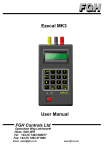
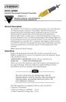
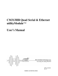
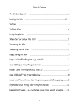
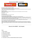
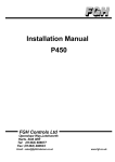
User Manual
Series 256 Programmer
And 6 channel Controller
FGH Controls Ltd
Openshaw Way,Letchworth
Herts. SG6 3ER, England
Tel: (01462) 686677
Fax: (01462) 480633
Series 256 User Manual
Page 1
Series 256 User Manual
Contents
1
Installation. .................................................................................................................................... 2
1.1 Panel Mounting. ........................................................................................................................................ 2
1.2 Electrical Connections ............................................................................................................................... 2
1.2.1 Supply............................................................................................................................................... 3
1.2.2 Sensors............................................................................................................................................. 3
1.2.3 Outputs ............................................................................................................................................. 4
1.2.4 Serial Communications...................................................................................................................... 4
1.3 User Switch Settings.................................................................................................................................. 7
1.3.1 Programmer/Controller switch ........................................................................................................... 7
1.3.2 P256 Programmer DIL Switch meanings ........................................................................................... 7
1.3.3 S256 Controller DIL switch meanings ................................................................................................ 8
1.4 PCB Jumper Links..................................................................................................................................... 9
1.4.1 Thermocouple break detection .......................................................................................................... 9
2
Operation ..................................................................................................................................... 10
2.0 General ................................................................................................................................................... 10
2.1 Operation of controller ............................................................................................................................. 10
2.2 Operation of profile generator .................................................................................................................. 11
2.2.1 Normal profile operation. ................................................................................................................. 11
2.2.2 The affect of Holds. ......................................................................................................................... 11
2.2.3 Supply failures during a profile. ....................................................................................................... 12
3
Controller displays...................................................................................................................... 12
3.1
3.2
3.3
3.4
3.5
4
Profiler displays .......................................................................................................................... 15
4.1
4.2
4.3
4.4
4.5
4.6
4.7
5
Controller overview.................................................................................................................................. 13
Manual setpoint ....................................................................................................................................... 14
Setpoint mode ......................................................................................................................................... 14
Setpoint trim ............................................................................................................................................ 14
Setpoint clamp ........................................................................................................................................ 15
Profiler overview...................................................................................................................................... 15
Heating rate............................................................................................................................................. 16
Soak temperature.................................................................................................................................... 16
Soak time ................................................................................................................................................ 16
Cooling rate............................................................................................................................................. 17
End temperature...................................................................................................................................... 17
Profile start/stop control ........................................................................................................................... 17
Serial communications ............................................................................................................... 18
5.1 Data format ............................................................................................................................................. 18
5.2 Message structure ................................................................................................................................... 18
5.2.1 Read transactions ........................................................................................................................... 18
5.2.2 Write transactions ........................................................................................................................... 19
5.2.3 Instrument address.......................................................................................................................... 19
5.2.4 Parameter code and SS field........................................................................................................... 19
5.2.5 Data field ........................................................................................................................................ 20
5.3 Normal message responses .................................................................................................................... 20
5.4 Error message responses........................................................................................................................ 21
6
Specifications.............................................................................................................................. 22
6.1 General ..................................................................................................................................................... 22
6.2 Controllers................................................................................................................................................. 22
6.3 Profiler ...................................................................................................................................................... 23
M53 Issue 0.4
Page 2
1
Series 256 User Manual
Installation.
1.1
Panel Mounting.
The instrument will fit into a DIN standard 92mm x 92mm +0.8mm -0 square cut-out and will
accommodate a panel thickness up to 7mm.
96mm
16mm
152mm
96mm
The instrument projects behind the panel by less than 152mm including terminal connections
If IP65 sealing is required then ensure that the panel sealing gasket is fitted into position
behind the bezel. The gasket may be omitted If IP65 sealing is not required.
Unscrew the two instrument mounting screws on the bezel until the
two retaining ears are near their rearmost positions. Whilst holding
the retaining ears retracted within the recesses, fit the instrument
into the panel cut-out. Hold the instrument in place and gently
tighten the two mounting screws on the front of the instrument until
the gasket is compressed and the instrument is firmly retained in
the panel. DO NOT OVER TIGHTEN THE SCREWS.
Mounting
Screws
Additional measures will be required to seal multiple instruments if
5mm min
92mm
+0.8
-0
Panel Cutout
5mm min
they are mounted in a common slot. These measures may consist of sealing compound or
other devices at the discretion of the installer.
1.2
Electrical Connections
M53 Issue 0.4
Series 256 User Manual
Page 3
All electrical connections are made to the rear of the instrument via screw terminal blocks.
Each terminal block plugs into a receptacle in the rear of the instrument and may be
unplugged to allow easy wiring and to withdraw the instrument from the panel.
1.2.1 Supply
Mains power should be connected to the three way mains
terminal block. The instrument will accept 95 to 253 V RMS at
50 to 60Hz and consumes approx. 6VA. A good earth
connection is essential for safety and screening purposes and
this is internally connected to the metal case of the
instrument.
Earth
Neutral
Line
1.2.2 Sensors
Connect the thermocouple sensors to the 12 way terminal block. These should be wired in
either compensating or extension cable appropriate to the type of thermocouple used. As
standard the 256 series instruments use Type K thermocouples. The colour codes for type
K are given in the table below.
Zone 1 TC
Type K Thermocouple International Colour Codes
+
- International
IEC 584-3
+
- American
ANSI MC96-1
+
- British
BS 1843-1981
Sheath
Green
Positive
Green
Negative
White
Sheath
Yellow
Positive
Yellow
Negative
Red
Sheath
Red
Positive
Brown
Negative
Blue
+
-
Zone 2 TC
Zone 3 TC
Zone 4 TC
Zone 5 TC
Zone 6 TC
+
-
M53 Issue 0.4
Page 4
Series 256 User Manual
1.2.3 Outputs
Common
The 6 zone controller outputs and the reverse
Zone 1 O/P
thermocouple alarm output should be wired to the 9 way
Zone 2 O/P
connector. Each output consists of a normally open relay
Zone 3 O/P
contact rated at 0.5A RMS at 253V maximum into a
Zone 4 O/P
resistive load.
Zone 5 O/P
Warning.
Zone 6 O/P
Each relay is internally fitted with a CR arc suppression
Rev. TC Al
device which will result in a small residual current flow
Not Used
(approx. 4mA at 250V) when the contact is open. This
small current may result in very light loads failing to switch
off.
If this is the case DO NOT remove the internal arc suppression devices. A 10K, 10W
resistor should be connected across the load, this will usually solve any problem. The
resistor will get hot so take care to mount it so that this does not cause a hazard.
Com
Line
OP 1
Supply
Neutral
OP 2
OP 3
OP 4
OP 5
OP 6
Loads
OP A
Reverse TC Alarm
1.2.4 Serial Communications
All series 256 instruments are equipped with two RS422 standard serial communications
ports. This allows the units to communicate with each other and any other suitable
equipment over distances up to 1200m. The HOST port is used for communications with a
host computer system for monitoring or recording purposes. The LOCAL port is intended
purely for communications between series 256 instruments only and is used for the transfer
of setpoints and control information.
Local
Controller
Comms Network
Host
Computer
Comms Network
M53 Issue 0.4
TX+
TXRX+
RXTX+
TXRX+
RXCommon
Series 256 User Manual
Computer
Page 5
HOST
HOST
HOST
HOST
P256
S256
S256
S256
LOCAL
LOCAL
LOCAL
LOCAL
Programmer
& Zones 1- 6
Optional
Zones 7- 12
Optional
Zones 13- 18
Optional
Zones 19- 24
The serial communications may be connected using either the two or four wire system. The
instrument uses a balanced voltage communications system which will perform well under
most situations provided some simple guidelines are observed.
1. The communications wiring should be implemented using a suitable, screened twisted
pair cable. The cable screen should be earthed at one point only.
2. The cable should be routed well away from sources of electrical noise such as motors,
contactors and any other high voltage wiring.
3. The network should be wired as a daisy chain, taking the wires into one instrument and
hence on to the next. Wiring spurs should be avoided. Take care to continue the cable
screen on to the next instrument.
4. For long cable runs or noisy environments it may be necessary to fit a terminating
resistor to the network. The terminator ( a 200Ω resistor) should be fitted between RX+
and RX- on both the computer and the furthest instrument. For two wire networks this
resistor should be fitted at the computer end only. Only one such terminator should be
fitted on each wire pair.
4 Wire Connection to host computer.
RXTXRX+
TX+
TX-
RX-
TX+
Com
RX+
Com
Earth
Host Computer
TX-
RXTX+
Com
RX+
Series 256
Host Port
Terminating Resistor
(Optional)
Series 256
Host Port
M53 Issue 0.4
Page 6
Series 256 User Manual
The above diagram shows the connections for 4 wire RS422 operation. This method of
connection uses a separate pair of wires for transmission and reception and is the preferred
connection method. Although called the '4 wire' connection, a fifth common wire is shown on
the diagram. This wire should be fitted if at all possible
2 Wire connection to host computer.
Terminating Resistor
(Optional)
TX-
Data-
TX+
RX-
Data+
RX+
Com
Com
Earth
Host Computer
TX-
RXTX+
Com
Series 256
Host Port
RX+
Series 256
Host Port
The above diagram shows the connections for 2 wire RS485 operation. This method of
connection uses a single pair of wires for both transmission and reception with the data
direction being controlled by the currently active device. As in the 4 wire connection, a
common wire is shown on the diagram. This wire should be fitted if at all possible.
Controller network connection.
When more than 6 control zones are needed, additional S256 controller instruments are
required. These instruments are connected to the P256 programmer via the local
communications port.
RX-
TX-
RX+
TX+
TX-
RX-
TX+
RX+
Com
Com
Earth
Controller
Local Port
Programmer
Local Port
M53 Issue 0.4
TX-
RXTX+
Com
RX+
Controller
Local Port
Series 256 User Manual
Page 7
1.3
User Switch Settings
The instrument type is set by means of the switch on the back panel of the instrument.
While aspects of the instruments operation are set by the user on the options DIL switch.
This switch is accessible through a cut-out in the case at the bottom of the instrument. Use
a narrow pointed device such as a ball point pen to set the switches to the required
positions. The meanings of the DIL switch settings are different between the Programmer
version (P256) and controller version (S256).
1.3.1 Programmer/Controller switch
The Programmer/Controller selector switch is situated on the back panel of the instrument.
This switch should only be operated when the instrument is powered off.
Move the switch to the S256 position to specify that the instrument is to be used as a slave
controller.
Move the switch to the P256 position to specify that the instrument is a profiler and
controller.
1.3.2
P256 Programmer DIL Switch meanings
Hold Type
Temp. Units
Trim & Clamp
Hold Band
Comms Address
1 2 3 4
5 6 7 8
ON
Switches 1 and 2 are used to select the type of hold operation.
SW 1
OFF
OFF
ON
ON
SW 2
OFF
ON
OFF
ON
Hold Type
Rates, Below setpoint only
Rates, Above and below setpoint
Rates and Soaks, Below setpoint only
Rates and Soaks, Above and below setpoint
Switch 3 is used to select the temperature units required.
SW 3
OFF
ON
Temperature Units
Degrees Celsius
Degrees Fahrenheit
Switch 4 is used to select whether or not the operator is allowed to apply trims and clamps
to the setpoint value.
SW 4
OFF
ON
Trim and Clamp
Trim and clamp Disabled
Trim and clamp Enabled
Switches 5 and 6 set the unit's hold band in multiples of the unit's prop band (Xp) as follows:
M53 Issue 0.4
Page 8
Series 256 User Manual
Note that the Hold band is defined as the maximum temperature difference between the
controller's set-point and temperature that is allowed before the profiler goes into a 'hold'
condition. Thus if the set-point is 300, prop band is 10, Hold band is twice and both above
and below hold is set then:
Hold occurs whenever the temperature is less than 280 or greater than 320. If the
temperature is between 280 and 320 then no hold will occur.
SW 5
OFF
ON
OFF
ON
SW 6
OFF
OFF
ON
ON
Hold Band
Holds Disabled
Xp x 1
Xp x 2
Xp x 3
Switches 7 and 8 set the unit's communications base address.
SW 7
SW 8
Comms Base Address
OFF
OFF
Address = 00
OFF
ON
Address = 10
ON
OFF
Address = 20
ON
ON
Address = 30
1.3.3
S256 Controller DIL switch meanings
Unit Address
Degrees C/F
No. of controllers
Base Address
1 2 3 4
5 6 7 8
ON
Switch 1 is used to select the number of controllers required.
SW 1
OFF
ON
No. of controllers
All 6 controllers are used
First 3 controller only are used
Switch 2 must be set to the same temperature units as the P256 (OFF for C, ON for F).
Switches 3, 4, 5 and 6 set the unit's communications address and controller number.
SW 3
OFF
OFF
OFF
OFF
OFF
OFF
OFF
ON
ON
SW 4
OFF
OFF
OFF
ON
ON
ON
ON
OFF
OFF
SW5
OFF
ON
ON
OFF
OFF
ON
ON
OFF
OFF
SW6
ON
OFF
ON
OFF
ON
OFF
ON
OFF
ON
Unit Address
Base address+1, Controllers 7 to 12
Base address +2, Controllers 13 to 18
Base address +3, Controllers 19 to 24
Base address +4, Controllers 25 to 30
Base address +5, Controllers 31 to 36
Base address +6, Controllers 37 to 42
Base address +7, Controllers 43 to 48
Base address +8, Controllers 49 to 54
Base address +9, Controllers 55 to 60
Switches 7 and 8 must be set to same comms base address as the P256.
M53 Issue 0.4
Series 256 User Manual
Page 9
1.4
PCB Jumper Links
In addition to the DIL switch there are two jumper links which may be set by the user.
To gain access to these links, the instrument
printed circuit boards must be removed from the
case.
Power Supply Input Board CPU Board
Unplug all wiring connectors and remove the
rear plate retaining screws ( two screws top and
bottom). Lift off the rear plate and pull out the
required PCB
Adjust the link settings as required and then
reassemble the instrument by plugging in the
PCBs. Note that there are no PCB card guides
until the PCB is almost fully inserted.
Refit the rear plate and reconnect all wiring
connectors.
1.4.1 Thermocouple break detection
The instrument can detect broken zone thermocouples. If break detection is switched on, a
broken thermocouple will be measured as over range. This will cause the zone controller to
turn off the output for that zone. If break detection is switched off, a broken thermocouple
will not be detected and its reading will float. Use the jumper link on the Input board to
enable or disable thermocouple break detection as required.
Thermocouple Break
Detection
OFF
ON
Input Board
M53 Issue 0.4
Page 10
2
Series 256 User Manual
Operation
2.0
General
The P256 operates as a self contained, 3 segment profile generator and 6 identical zone
controllers. The S256 has only the 6 zone controllers. Both have a reverse TC alarm feature
that turns off a zone and closes relay A if heat is applied to an accidentally reversed TC.
P256
Profile
Generator
Reverse
TC Alarm
Controller
1
Controller
2
Controller
3
Controller
4
Controller
5
Controller
6
TC
OP
Zone 1
TC
OP
Zone 2
TC
OP
Zone 3
TC
OP
Zone 4
TC
OP
Zone 5
TC
OP
Zone 6
A larm
OP
2.1
Operation of controller
There are 6 controllers available in every Series 256 instrument. Each controller can
operate in Automatic or Manual modes.
Automatic Mode.
The controller uses the setpoint from the profile generator. The operator may apply a local
trim to this setpoint and specify a high setpoint limit (clamp). The trim and clamp facilities
can be disabled if required using DIL switch 4.
Profile Setpoint
Man SP
SP Trim
HI Clamp
Man
Auto
SP
OP
Controller
MV
Zone TC
M53 Issue 0.4
Zone Output
Series 256 User Manual
Page 11
Manual Mode.
The controller uses a fixed manual setpoint entered by the operator.
All controllers operate in proportional only mode using a fixed proportional band setting of
10°C (18°F) and generate a time proportioning output with a cycle time of 20 seconds.
2.2
Operation of profile generator
The profile generator is used to generate the setpoint time-temperature profile. Each profile
consists of four distinct stages.
2.2.1
Normal profile operation.
Temperature
Soak Level
Heating Rate
Cooling Rate
Soak Time
End Temp
Hottest Zone Temp
Time
READY
HEATING
SOAK
COOLING
READY
Ready Stage.
The profile generator is not running and the temperature setpoint is maintained at zero.
Heating Stage.
When the profile is started, the temperature setpoint is ramped from the current zone hottest
temperature up to the soak temperature at the specified rate.
Soak Stage.
The temperature setpoint is maintained at the soak temperature for the specified soak time.
Cooling Stage.
The temperature setpoint is ramped downwards from the soak temperature at the specified
cooling rate until it reaches the End temperature. At this point the profile ends and the
profile generator returns to the Ready stage.
2.2.2 The affect of Holds.
The operation of the profile generator may be modified by the use of Holds.
A Hold comes into affect if any zone temperature deviates from setpoint by more than the
current Hold Band setting.
M53 Issue 0.4
Page 12
Series 256 User Manual
When the profile generator is in Hold both the profile setpoint and profile time-base are
frozen for the duration of the Hold. This effectively pauses the
profile until the offending zone temperature has come back
within limits.
If a Hold occurs during a ramp stage, the ramp is suspended for
the duration of the hold. This has the affect of extending the
expected ramp time.
HOLD
HOLD during a ramp
If a hold occurs during a soak stage, the soak time is stopped
for the duration of the hold. This guarantees that all zones have
been soaked to the required tolerance for the required time.
Obviously the apparent soak time may be extended if a hold
does occur.
1 Hour
1 Hour
HOLD
2.2.3
Supply failures during a profile.
HOLD during a 2 hour soak
Zone temps fall
while power off
Supply interruption during a ramp.
If the profiler is executing a ramp and a supply
interruption occurs. It is very likely that during the
power outage the zone temperatures will drop.
Upon supply restoration the instrument forces its
profile setpoint to be equal to the hottest of the
zone temperatures and continues the ramp form
there.
Supply interruption during a soak.
If the profiler is executing a soak and a supply
interruption occurs. It is very likely that during the
power outage the zone temperatures will drop.
Upon supply restoration the instrument forces its
profile setpoint to be equal to the hottest of the
zone temperatures and ramps the setpoint back
to the soak level at the heating ramp rate. When
the setpoint reaches the soak level the soak timer
is restarted from zero.
3
Ramp continues
from hottest zone
Power OFF
Power ON
Zone temps fall
while power off
Soak Level
Soak continues
SP ramps back to
Soak level.
Power OFF
Power ON
Controller displays
The controller displays consist of a controller overview and a scroll of up to four parameter
displays for each control zone. The diagram below shows the relationship between each of
the displays.
M53 Issue 0.4
Series 256 User Manual
Page 13
Controller
Overview
= Show SPs
1
Controller #1
2
#2
3
#3
4
#4
Profiler
Overview
5
#5
6
Controller #6
Manual
Setpoint
Manual
Setpoint
1
6
Setpoint
Mode
Setpoint
Mode
1
6
Setpoint
Trim
Setpoint
Trim
1
6
Setpoint
Clamp
Setpoint
Clamp
1
6
The user moves between each display by pressing one of the buttons. The instrument will
emit a short beep every time a button is pressed.
3.1
Controller overview
The controller overview display is used to supervise the operation of the six internal zone
controllers.
Deviation Bargraph
Setpoint type AUTO
Setpoint type MANUAL
Controller number
1
a
1000
2
a
1000
3
m
1000
4
a
Hold
5
m
1000
6
m
1000
Zone temperature
Zone in Hold
User Prompt
for S/P,
for Profile
Each zone controller is represented by a rectangle on the display. Within this rectangle the
current zone temperature is shown along with the setpoint mode.
At the top of each rectangle is a zone deviation bargraph
this represents the error between the current zone
temperature and the setpoint. The bargraph is scaled –
15 to +15 degrees from left to right with zero error in the
centre. The graph is shaded from the centre outwards.
Shading on the right hand side means that the zone is
Too Hot
Too Cold
-15º
-10º
-5º
0º
+5º
+10º
+15º
+8º error indicated
M53 Issue 0.4
Page 14
Series 256 User Manual
too hot. Shading on the left means that the zone is too cold.
If the profiler is running and a zone has caused the profiler to go into hold then that zone
temperature will be displayed flashing alternatively with the word Hold.
To display the current zone setpoints, press and hold the up button. While the button is
depressed the displayed zone temperatures will be replaced with the current zone setpoints.
Release the button and the display will return to normal.
Press the down button to monitor the profiler via the Profiler Overview display.
The setup parameters for each zone controller may be accessed by pressing the button
corresponding to the controller number. For example press the button 3 to access controller
3 and so on
3.2
Manual setpoint
A zone controller may be in either automatic or manual
CONTROLLER # 1
modes. In automatic, the zone controller uses the
setpoint generated by the profiler. In manual mode the
15
Manual S/P =
controller uses a static setpoint entered by the operator.
Use the up and down buttons to enter the required
manual setpoint in degrees.
Use
to change value
Use 1 for more...
Alternatively press the button corresponding to the
controller number to advance to the Setpoint Mode
display.
If no buttons are pressed for 20 seconds then the display will revert back to the Controller
Overview.
3.3
Setpoint mode
Use this display to toggle the zone controller between
CONTROLLER # 1
automatic and manual setpoint modes. Use the up
button to select AUTO mode and the down button to
AUTO
S/P mode is
select MANUAL mode. If the controller mode is modified
then this change is implemented immediately so please
Use
to change mode
ensure that the manual setpoint value is correct before
Use 1 for more...
selecting manual mode.
Alternatively press the button corresponding to the
controller number to advance to the Setpoint Trim display.
If no buttons are pressed for 20 seconds then the display will revert back to the Controller
Overview.
3.4
Setpoint trim
Use this display to apply a setpoint offset to the zone
CONTROLLER # 1
controller in automatic mode. Positive values will cause
this zone controller to control slightly hotter than the
20
Auto S/P Trim =
current profile setpoint. Negative values will cause this
zone controller to control slightly colder than the profile
Use
to change value
setpoint. Any value between –50 and +50 degrees may
Use 1 for more...
be entered.
The trim facility is only affective if the zone controller is
in automatic mode and the setpoint trim facility is enabled on the DIL switch.
M53 Issue 0.4
Series 256 User Manual
Page 15
Alternatively press the button corresponding to the controller number to advance to the
Setpoint Clamp display.
If no buttons are pressed for 20 seconds then the display will revert back to the Controller
Overview.
3.5
Setpoint clamp
Use this display to apply a high limit to the setpoint used
CONTROLLER # 1
by this zone controller in automatic mode. This clamp will
limit the maximum control temperature for this zone.
Auto S/P Clamp = 1000
The clamp facility is only affective if the zone controller is
in automatic mode and the setpoint clamp facility is
enabled on the DIL switch.
Use
to change value
Use 1 for more...
Alternatively press the button corresponding to the
controller number to advance to the Controller
Overview display.
If no buttons are pressed for 20 seconds then the display will automatically revert back to
the Controller Overview.
4
Profiler displays
The diagram below shows the relationship between each of the displays in the profiler.
Controller
Overview
+ 1 = FAST Heating
Profiler
Overview
+ 4 = FAST Cooling
1
2
3
4
5
6
Heating
Rate
Soak
Temp
Soak
Time
Cooling
Rate
End
Temp
Start
Stop
1
2
3
4
5
6
The user moves between each display by pressing one of the buttons. The instrument will
emit a short beep every time a button is pressed.
4.1
Profiler overview
The profiler overview display is used to monitor and set up the operation of the profile
generator by means of a mimic diagram.
Current profile setpoint
Fast
2
3
Cont.
4
Current profile segment
Profile parameters
1
97°C
5
2.5
1
50
2
800
3
4
500
5
100
6 Heating
M53 Issue 0.4
Page 16
Series 256 User Manual
The diagram shows a typical heat-soak-cool profile with each stage numbered. The large
number in the centre of the display shows the current profile setpoint with the current
segment indicated by a flashing number.
While the profile is ramping up or down the user may speed up the ramp using the Fast
facility.
To Fast through a heating ramp, press and hold down the up button and press button 1.
To Fast through a cooling ramp, press and hold down the up button and press button 4.
Press the down button to monitor the profiler via the Controller Overview display.
At the bottom of the display each profile parameter is listed adjacent to a number. To modify
a parameter press the corresponding numbered button.
4.2
Heating rate
Use this display to set the profile heating rate in degrees
per hour. This is the rate at which the profile setpoint
increases from the starting temperature to the desired
soak temperature. If the profiler is currently running the
heating ramp, this change will take affect immediately.
Enter a rate of zero if you require to step change the
setpoint to the soak temperature.
HEATING RATE
Heat at
600
Deg/Hr
Use
to change value
Use 1 for more...
Press button 1 to return to Profiler Overview display.
If no buttons are pressed for 20 seconds then the display will revert back to the Profiler
Overview.
4.3
Soak temperature
Use this display to set the soak temperature in degrees.
This is the temperature at which the profile setpoint
remains static for the soak period. If the profiler is
currently performing the soak and this value is changed,
then the setpoint will be ramped to the new soak
temperature at the specified heating rate and the soak
will be restarted.
SOAK TEMPERATURE
Soak at
800
Degrees
Use
to change value
Use 2 for more...
Press button 2 to return to Profiler Overview display.
If no buttons are pressed for 20 seconds then the display will revert back to the Profiler
Overview
4.4
Soak time
Use this display to set the profile soak time in hours. This
is the time for which the profile setpoint remains at the
desired soak temperature. If the profiler is currently
performing the soak and this time is reduced below the
currently elapsed soak time, the soak will terminate
immediately and the cooling ramp will commence.
Enter a time of zero if you do not require a soak.
M53 Issue 0.4
SOAK TIME
Soak for
(
2.5
Hours
1.8 to go )
Use
to change value
Use 3 for more...
Series 256 User Manual
Page 17
If the profiler is running then the remaining soak time will be shown in brackets below the
target time.
Press button 3 to return to Profiler Overview display.
If no buttons are pressed for 20 seconds then the display will revert back to the Profiler
Overview.
4.5
Cooling rate
Use this display to set the profile cooling rate in degrees
per hour. This is the rate at which the profile setpoint
reduces from the soak temperature to the desired end
temperature. If the profiler is currently running the
cooling ramp, this change will take affect immediately.
Enter a rate of zero if you require to step change the
setpoint to the end temperature.
COOLING RATE
Cool at
50
Deg/Hr
Use
to change value
Use 4 for more...
Press button 4 to return to Profiler Overview display.
If no buttons are pressed for 20 seconds then the display will revert back to the Profiler
Overview.
4.6
End temperature
Use this display to set the profile ending temperature in
degrees. This is the temperature at which the cooling
ramp terminates and the profiler returns to its ready
state. If the profiler is currently running the cooling ramp,
and this value is increased above the current profile
setpoint, the profile will end immediately.
END TEMPERATURE
End at
100
Degrees
Use
to change value
Use 5 for more...
Press button 5 to return to Profiler Overview display.
If no buttons are pressed for 20 seconds then the display will revert back to the Profiler
Overview.
4.7
Profile start/stop control
Use this display to start or stop the profiler.
If the profiler is currently running then press the down
button to stop the profiler and return it to the ready state
START/STOP CONTROL
Profiler is
RUNNING
Use
to STOP
Use 6 for more...
START/STOP CONTROL
If the profiler is ready (not running) then press the up
button to start the profile.
Profiler is
READY
Use
to START
Use 6 for more...
M53 Issue 0.4
Page 18
Series 256 User Manual
Press button 6 to return to Profiler Overview display.
If no buttons are pressed for 20 seconds then the display will revert back to the Profiler
Overview.
5
Serial communications
The unit has 2 serial communications channels. The local communications port is used
solely for communications between series 256 devices and is not available for use by the
user. The host port however is available to the user and this section provides the details
required to implement successful data communications between instrument and PC.
5.1
Data format
Communications may be performed in either 2 wire RS485 or 4 wire RS422 standards. Both
modes are half duplex only.
The data format and Baud rate are fixed as follows.
Baud Rate
Start bits
Word length
Parity
Stop bits
9600
1
7 bits
Odd
1
5.2
Message structure
All series 256 instruments act as slave devices. This means that an instrument will not itself
initiate a transaction, it merely responds to transaction requests initiated by a host computer
or other similar device. Messages consist entirely of printable ASCII characters so
transaction data may be conveniently tested or monitored using any terminal device.
There are two types of transaction which are supported by the 256 instrument. Read
transactions (requests for data from the 256) or write transactions (data sent to the 256).
5.2.1 Read transactions
Read transactions are used to acquire data from the 256 and consist of messages of the
following general form.
RAAPSS<CR>
Where R
AA
P
SS
<CR>
= Read message header ASCII code 52h
= Instrument address
= Parameter code
= Secondary parameter code
= Message terminator ASCII code 0Dh
Messages to the instrument may include spaces or linefeeds if required. These will be
ignored. Messages from the instrument will not contain either linefeeds or spaces.
M53 Issue 0.4
Series 256 User Manual
Page 19
5.2.2 Write transactions
Write transactions are used to write data into the 256 and consist of messages of the
following general form.
WAAPSSD…D<CR>
Where W
AA
P
SS
D…D
<CR>
= Read message header ASCII code 57h
= Instrument address
= Parameter code
= Secondary parameter code
= Data to write
= Message terminator ASCII code 0Dh
Messages to the instrument may include spaces or linefeeds if required. These will be
ignored. Messages from the instrument will not contain either linefeeds or spaces.
5.2.3 Instrument address
Each instrument must be given a unique address between 00 and 39. This address is set
on the configuration DIL switch (see section 1.3). The address field of the message consists
of two ASCII numerals and determines to which instrument the message is directed. An
instrument will ignore a message that does not contain its own address. The user may
choose to use the broadcast address facility. This is a means of writing data to a group of
instruments at the same time. Either address character may be replaced by the character X
(ASCII code 58h).
For example if a write message is sent to address 2X, then all instrument addresses 20 to
29 will action the message.
Please note instruments written to using the broadcast address facility will not reply to the
message.
5.2.4 Parameter code and SS field
The parameter code field of the message is a single ASCII character, this identifies the
parameter group within the instrument which is the target of the read or write message.
Used in conjunction with the two digit SS field the instrument is able to identify the specific
parameter required.
Code
A
A
B
C
K
L
M
N
O
Q(p)
Q(p)
R(p)
S(p)
SS
01 to 06
07
01 to 06
01 to 06
01 to 06
01 to 06
01
01 to 06
01 to 06
01
11
01
11
R/W
R
R
R
R/W
R/W
R/W
R
R
R/W
R
R
R
R/W
Parameter
Zone temperature 1 to 6
Cold junction temperature
Zone outputs 1 to 6
Zone manual setpoints 1 to 6
Zone setpoint trims 1 to 6
Zone setpoint clamps 1 to 6
Zone hold status
Zone actual setpoints 1 to 6
Zone setpoint types 1 to 6
Status of profiler
Hold status of profiler
Current profiler setpoint
Profiler heating rate
Data Range
0 to 2000
0 to 100
0 to 1000
0 to 2000
-50 to +50
0 to 2000
Units
Degs
Degs
0.1 %
Degs
Degs
Degs
(1)
0 to 2000
Degs
(1)
(1)
0 to 1
0 to 2000
0 to 1000
Degs
Degs/Hr
M53 Issue 0.4
Page 20
S(p)
T(p)
U(p)
U(p)
V(p)
Z(p)
(p)
(1)
Series 256 User Manual
21
11
11
21
01
01
R/W
R/W
R/W
R/W
R
W
Profiler cooling rate
Profiler soak time
Profiler soak temperature
Profiler end temperature
Profiler soak elapsed
Profiler start/stop
0 to 1000
0 to 1000
0 to 2000
0 to 2000
0 to 1000
0 to 1
Degs/Hr
0.1 Hrs
Degs
Degs
0.1 Hrs
Only available on P256
Coded data field see section 5.3
5.2.5 Data field
The data field part of the message consists of 4 ASCII numeric characters preceded by an
optional minus sign. The data field should be left padded with zeros such that there are
always 4 numeric characters.
For example
0000
0100
-0100
represents zero
represents the number 100d
represents the number -100d
5.3
Normal message responses
A successful message received by the instrument will usually initiate a message response.
This will consist of a message of the following general form.
*AAPSSD…D<CR>
Where *
AA
P
SS
D…D
<CR>
= Response message header ASCII code 2Ah
= Instrument address
= Parameter code
= Secondary parameter code
= Data
= Message terminator ASCII code 0Dh
The returned data field contains either the data requested (read transaction) or confirmation
of the data just written (write transaction). All data returned is numeric and is of the type
defined in section 5.2.5
Certain parameters however use coded data fields as follows
Parameter M (controller hold status)
This parameter returns a bit weighted number with the following bit meanings
Bit
Meaning
0
zone 1 in Hold
1
zone 2 in Hold
2
zone 3 in Hold
3
zone 4 in Hold
4
zone 5 in Hold
M53 Issue 0.4
Series 256 User Manual
Page 21
5
zone 6 in Hold
for example the number 6 indicates that zones 2 and 3 are in hold.
Parameter O (controller setpoint type)
This parameter returns
0 for controller in manual setpoint
1 for controller in automatic setpoint
Parameter Q01 (profiler status)
This parameter returns a number with the following bit meanings
Number
Meaning
0
Ready
1
Servo starting
2
Heating
4
Soaking
8
Cooling
Parameter Q11 (profiler hold status)
This parameter returns
0 for profiler NOT in hold
1 for profiler in Hold
5.4
Error message responses
Commands to the P256, other than broadcast commands, that contain an error or cannot be
understood result in an error reply of the general form:
?AAEF<CR>
Where ?
AA
= Message header ASCII code 3Fh
= Address of the replying instrument.
E
= Character fault error code.
F
= Message fault error code.
<CR> = Message terminator ASCII code 0Dh
Character error codes.
Field E is a single ASCII hexadecimal number who's binary weighting indicates the type of
character corruption that may have given rise to the error:
BIT MEANING
3
break in transmission
2
parity error
1
framing error
0
receiver over-run error
Message error codes.
Field F is a single ASCII hexadecimal number who's binary weighting indicates the type of
message fault that may have given rise to the error:
BIT MEANING
3
Illegal header
2
Illegal parameter code or number
1
Illegal data
M53 Issue 0.4
Page 22
Series 256 User Manual
0
Illegal number of characters in command.
In general only one possible error will be identified thus either fields E or F will be zero.
Where a command character is found to be corrupted then the receiving instrument(s) will
treat the corrupted character as the final character of the message and will attempt to
interpret it. Where the corruption has occurred in the header or address fields of the
message then no reply is given and message is ignored. If, as is likely, the message
continues after the corrupted character then the instruments will treat that part of the
message after the corruption as a new message. This will generate a reply if the supposed
address in the remainder of the message is recognised by an instrument: this is bound to
result in an error message but fields E and F will refer, not to the original corruption, but to
the meaningless nature of the remainder of the message. For this reason no great reliance
should be placed on the validity of either E or F.
When the instrument detects a communications error it will emit a short beep from its
internal sounder.
6
Specifications
6.1 General
Front bezel
Bezel size
Panel cut out
Case
Case depth
Connectors
Display window
Display
Display backlight
Buttons
Panel fixing
Weight
Protection
Safety
Installation Cat.
Pollution degree
EMC
Serial interface
Supply
Environment
Dark grey Noryl SE1
96 x 96 to DIN 43700
92 +0.8/-0 square
Zinc plated sheet steel
152 including terminals
2 part 5.08 pitch for up to 14 AWG
Polycarbonate
Graphic LCD panel 128 x 64 pixels
Continuous yellow-green LED
8 off blue-green silicone rubber
2 off M3 screws allowing withdrawal of entire unit from front of panel
Approx. 800g
Front: IP65, Rear IP00
BS EN 61010-1
II
2.
BS EN 50081-2, BS EN 50082-2
2 off RS422/RS485
95-253 V rms, 48 - 62 Hz, < 10VA
Operating 0 - 60 C, 5 - 95% rh non-condensing
Storage -10 - 65 C, 5 - 95% rh non-condensing
6.2 Controllers
All controllers share the following common parameters:
Sensor
Units
M53 Issue 0.4
K to BS EN 60584-1 (others by special order)
Degrees C or F
Series 256 User Manual
Resolution
Sampling
Isolation
Break detection
Prop band
TP cycle time
Hold band
Hold type
TP output
Relay rating
Leakage
Page 23
Measurement:
0.1 degrees
Display:
1.0 degree
Every 0.735 seconds
100 V sensor – sensor
100 V sensor - earth
Up scale, sensor current 100 nA
10 degrees C ( 18 degrees F)
20 seconds
1, 2 or 3 times prop band
Below only or above and below
1 form A relay contact per controller
264 V rms max, 10 V dc min, 0.5 A resistive
Less than 4mA rms at 265 Vrms
Each controller has the following independent parameters:
Set point type
Manual set point
Auto s/p trim
Auto s/p clamp
Manual or Automatic
0 to 1200ºC (2000ºF) in 1 degree increments
+/- 50ºC ( +/- 90ºF) in 1 degree increments
0 to 1200ºC (2000ºF) in 1 degree increments
6.3 Profiler
The profiler has the following parameters:
Heating rate
Soak temperature
Soak time
Cooling rate
End temperature
Hold mode
0 (step) to 1000 degrees per hour in 1 increments
0 to 1200ºC (2000ºF) in 1 degree increments
0 to 100.0 Hrs in 0.1 Hr increments
0 (step) to 1000 degrees per hour in 1 increments
0 to 1200ºC (2000ºF) in 1 degree increments
Ramps only or ramps and dwell
M53 Issue 0.4
Page 24
M53 Issue 0.4
Series 256 User Manual