1
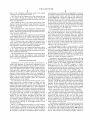
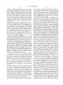
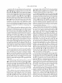
US006169535B1
(12) United States Patent
(10) Patent N0.:
(45) Date of Patent:
Lee
(54) MONITOR ADJUSTMENT CONTROL
US 6,169,535 B1
*J an. 2, 2001
OTHER PUBLICATIONS
(75) Inventor: Charles Lee, Simi Valley, CA (US)
Print out of Graphical User Interface of “Display Manager”
Computer Access Technology Corp., Santa Clara, CA, 1997.
(73) Assignee: Toshiba America Information
Systems, Inc., Irvine, CA (US)
Print out of Graphical User Interface of “CustoMaX” Philips
Electronics NV. (1994).
*
( )
'
-
Nonce'
This patent issued on a continued pros
ecution application ?led under 37 CFR
1.53(d), and is subject to the tWenty year
patent term provisions of 35 U.S.C.
Print out of Graphical User Interface of, and User’s Manual
for, “Monitor Soft Control” Multivideo Labs, Inc., Princ
eton, NJ.
154(a)(2).
Primary Examiner—Kent Chang
Under 35 U.S.C. 154(b), the term of this
patent shall be extended for 0 days.
(74) Attorney, Agent, or Firm—Pillsbury Madison & Sutro
LLP
(57)
ABSTRACT
(21) Appl. No.: 08/902,240
The described embodiments are directed to a method and
(22) Filed:
apparatus for adjusting a display through user inputs from a
graphical user interface. In particular, the described embodi
Jul. 29, 1997
ments are directed to such a graphical user interface includ
Related US. Application Data
(60)
Provisional application No. 60/051,288, ?led on Jun. 30,
1997.
ing a display Which illuminates a ?gure representative of the
cumulative adjustments made to the display. A computer
system including a video monitor having a CRT and display
(51)
Int. Cl.7 ..................................................... .. G09G 5/08
(52)
(58)
US. Cl. ......................... .. 345/145; 345/127; 345/204
Field of Search ................................... .. 345/204, 145,
display illuminated by the CRT. The computer system
345/146, 156, 157, 121, 127, 904, 123,
includes a host processor Which is capable of transmitting
342
control circuitry disposed therein. The control circuitry is
capable of maintaining at least one adjustment state of a
display adjustment signals to the control circuitry to change
the at least one adjustment state. Upon a user selection, the
(56)
References Cited
U.S. PATENT DOCUMENTS
4,991,023
5,270,821
5,448,697
2/1991 Nicols .
12/1993 Samuels .
9/1995 Parks et al. .
5,477,241
5,481,276
12/1995 Higgins et al. .
1/1996 Dickey et al. .
5,483,260
1/1996 Parks et al. .
5,499,040
3/1996 McLaughlin et al. .
5,550,556
5,565,897
8/1996 Wu et al. .
10/1996 Kikinis et al. .
5,570,108
10/1996 McLaughlin et al. .
display of the CRT illuminates an adjustment display includ
ing a single graphical image Which is representative of the
cumulative adjustments made to the display. A pointer
alloWs a user to move a cursor in the adjustment display to
click on and drag edges of the single graphical image to
effectuate adjustments to the display. The host processor
executes control routines to initiate the transmission of
adjustment signals to the control circuitry to change the at
least one adjustment state in response to user provided
pointer movements for dragging edges of the single graphi
cal image.
13 Claims, 4 Drawing Sheets
U.S. Patent
Jan. 2, 2001
Sheet 2 014
US 6,169,535 B1
109
. ...........
s
108
101
107
@5129 102
114
105
@115
. . . . . . ...
\
114.
104
.............. nimkiban.
128
130
/
131
d
U.S. Patent
Jan. 2, 2001
Sheet 3 of4
US 6,169,535 B1
U.S. Patent
Jan. 2, 2001
Sheet 4 of4
US 6,169,535 B1
US 6,169,535 B1
1
2
MONITOR ADJUSTMENT CONTROL
acteristics. The control circuitry typically includes control
parameters Which have an initial state Which is adjustable in
response to signals from the host. Each monitor in a line of
monitors typically includes control circuitry from the same
manufacturer having control parameters at the same initial
This application claims the bene?t of US. Provisional
Application No. 60/051,288, ?led Jun. 30, 1997.
BACKGROUND OF THE INVENTION
state. The control circuitry integrated into each monitor is
1. Field of the Invention
then typically adjusted by the same degree to properly adjust
The described embodiments are directed to a method and
the monitor to a predetermined state at the factory. For
monitors having been shipped from the factory, the current
GUI based systems, shoWing only the adjustments made in
apparatus for adjusting a display through user inputs from a
graphical user interface. In particular, the described embodi
a current adjustment session, do not easily alloW a technician
ments are directed to such a graphical user interface includ
ing a display Which illuminates a ?gure for making adjust
to readjust such a monitor to its original factory adjustment
ments made to the display.
2. Related Art
state.
Conventional computer monitors typically have built-in
control inputs for things such as brightness, contrast, picture
position, and siZing. These control inputs as described above
SUMMARY OF THE INVENTION
15
An obj ect of an embodiment of the present invention is to
provide a method and apparatus for adjusting a display
through a graphical user interface.
Another object of an embodiment of the present invention
require the user to reach to the monitor, sometimes to
different locations around the case, to ?nd the proper control.
adjustable attribute. Additionally, a neW monitor installed in
is to provide a simpli?ed method and apparatus for adjusting
a display to initial factory adjustment values.
Another object of an embodiment of the present invention
a computer system typically requires adjustment of the
is to provide a graphical image illuminated on a display
Moreover, the control inputs do not necessarily shoW the
adjustment limits or the present position of the particular
monitor controls. When a neW monitor is installed, it is not 25 Which represents the cumulative adjustments made to the
display.
unusual for the initial display on the monitor to be off-center,
skeWed, and the like. Thus, the set-up procedures must
provide for adjustments to the monitor so that the picture
Another object of an embodiment of the present invention
is to provide a single graphical image illuminated on a
may be properly adjusted initially.
display having a siZe, shape and orientation Which is rep
resentative of the cumulative adjustments made to the dis
A computer system typically includes a host computer
coupled to a monitor. NeWer computer systems permit the
user to make inputs to the host unit of the computer through
peripheral devices such as a keyboard or pointing device
(such as a mouse) to make adjustments to the monitor. In
response to these user inputs, the host computer may trans
play.
Brie?y, an embodiment of the present invention is
directed to a computer system including a video monitor
35
mit adjustment control signals interleaved With video signals
to control circuitry in the monitor. Thus, the need for
external control inputs on the monitor is eliminated.
Some systems, supported by WindoWs or a Macintosh
having a CRT and display control circuitry disposed therein.
The control circuitry is capable of maintaining at least one
adjustment state of a display illuminated by the CRT. The
computer system includes a host processor Which is capable
of transmitting display adjustment signals to the control
circuitry to change the at least one adjustment state. Upon a
user selection, the display of the CRT illuminates an adjust
operating system, provide graphical user interfaces (GUIs)
Which has someWhat simpli?ed the inputting of adjustment
ment display including a single graphical image Which is
information through a pointer controlled cursor. The “Cus
representative of the cumulative adjustments made to the
toMaX” system sold by Philips Electronics displays several
display. A pointer alloWs a user to move a cursor in the
cursor selectable buttons for receiving adjustment informa
tion. The “Display Manager” system sold by Computer
45
host processor eXecutes control routines to initiate the trans
Access Technology Corp. displays a draggable lever for
inputting adjustments for a selected characteristic. A graphi
cal shape represents the adjustments to the display made
mission of adjustment signals to the control circuitry to
change the at least one adjustment state in response to user
provided pointer movements for dragging edges of the
during a current adjustment session for the selected charac
teristic. The “Monitor Soft Control” system sold by Multi
Video Labs, Inc. generates a separate selectable display for
single graphical image.
By using a single graphical image for receiving user
inputs to adjust multiple characteristics of the display, and
representing the cumulative adjustments in the multiple
characteristics by the siZe, shape and orientation of the
receiving inputs for each display characteristic. Each select
able display includes its oWn draggable lever for receiving
adjustment inputs for the selected characteristic and its oWn
gauge for shoWing the adjustments made during the current
adjustment session. US. Pat. No. 5,565,897 assigned to
EloneX Technologies, Inc. describes multiple shapes Which
55
the cumulative adjustments made. Thus, a technician can
easily adjust a display according to its initial factory adjust
ment states as represented by the graphical image.
multiple shapes to initiate the transmission of display adjust
ment signals. When the multiple shapes are not rectangular,
BRIEF DESCRIPTION OF THE FIGURES
the user may click on and drag portions of the multiple
ing input adjustments are complex and employ multiple
images to correspond With different adjustable display char
graphical image, the described embodiments provide a con
sistent procedure for making the adjustments and recording
are calibrated to appear rectangular on a properly adjusted
monitor. The user may click on and drag portions of the
shapes until they are rectangular, thus putting the monitor in
its properly adjusted state.
The current GUI based systems for receiving and display
adjustment display to click on and drag edges of the single
graphical image to effectuate adjustments to the display. The
65
FIG. 1 shoWs a block diagram of a host computer system
connected to a CRT monitor, including remote control of
display functions according to an embodiment of the present
invention.
FIG. 2 shoWs a graphical image illuminated on a display
Which has a siZe, shape, and orientation Which is represen
US 6,169,535 B1
3
4
tative of the cumulative adjustments made to the display
according to the embodiment of FIG. 1.
executing logic, and performing computations; a memory
17, typically a random access memory (RAM) and hard disk
for storing control routines and data; a basic input/output
system (BIOS) 19; a keyboard controller 21 coupled to a
keyboard 23; and a pointer port 25 coupled to a pointer
device 27, Which may be a track ball, mouse, pen digitiZer,
or other types of pointer devices capable of moving a cursor
FIGS. 3a, 3b and 3c illustrate hoW a user adjusts the siZe
of the display through the graphical image illuminated
thereon, and hoW the graphical image represents such cumu
lative siZe adjustments.
FIG. 4 illustrates hoW a user adjusts the location of the
illuminated in the monitor 13. The elements described above
display through the graphical image illuminated thereon,
are bus connected by one or more bus structures represented
and hoW the graphical image represents such cumulative
location adjustments.
10
FIG. 5 illustrates hoW a user adjusts the rotational orien
It is Well knoWn in the art that there are many variations
tation of the display through the graphical image illuminated
thereon, and hoW the graphical image represents such cumu
lative rotational adjustments.
15
FIG. 6 illustrates hoW a user adjusts the horiZontal boWing
or pincushion effects of the display through the graphical
image illuminated thereon, and hoW the graphical image
represents such cumulative horiZontal boWing adjustments.
in the architecture shoWn for the host computer system of
FIG. 1 and the architecture is meant to be representative of
conventional architecture in general. There are, similarly,
many alternatives for the particular functional elements
shoWn. For example, FIG. 1 illustrates a keyboard 23 as an
input device. There are alternatives for input devices, such
as touch screens, pen pads, and the like, and such alterna
FIG. 7 illustrates hoW a user adjusts the horiZontal sym
tives may be used in other embodiments of the invention.
There are similarly several alternatives for pointer devices in
metry effects of the display through the graphical image
illuminated thereon, and hoW the graphical image represents
addition to the ones listed above.
such cumulative horiZontal symmetry adjustments.
FIG. 8 illustrates hoW a user adjusts the parallelism effects
of the display through the graphical image illuminated
by interconnecting bus 29 Which also connects to video
circuitry 33 through a video BIOS 31.
25
thereon, and hoW the graphical image represents such cumu
In the embodiment of FIG. 1, video circuitry is a VGA
subsystem 33, Which provides video dot data for a monitor
such as R, G, and B signals, 35, 37, and 39, and also
horiZontal synchroniZation (HSYNC) signals 41 and vertical
synchroniZation (VSYNC) signals 43, to a cable interface
lative parallelism adjustments.
45. These signals and ground connections are coupled to the
monitor 13 conventionally by a VGA cable 47, Wherein the
signals are coupled to separate conductors.
According to an embodiment, the host computer 11 may
transmit data to adjustment circuitry 52 of the monitor 13
FIG. 9 illustrates hoW a user adjusts the trapeZoidal effects
of the display through the graphical image illuminated
thereon, and hoW the graphical image represents such cumu
lative trapeZoidal adjustments.
DETAILED DESCRIPTION
through the VGA cable 47 by inserting serial data packets
Embodiments of the present invention are directed to a 35 betWeen pulses of the VSYNC signals 43 as described in
detail in US. Pat. No. 5,565,897 assigned to Elonex
Technologies, Inc. at Col. 4, line 23 through Col. 7, line 8.
In another embodiment, the host computer 11 may transmit
method and apparatus for interactively adjusting an elec
tronic display Which is adjustable for the effects of rotation,
siZe, parallelism, centering, trapeZoidism, boWing, and sym
metry. The display portion shoWs a single graphical image,
control signals to the adjustment circuitry 52 by using a code
to modulate the pulse Width of the VSYNC pulse as
described in detail in US. Pat. No. 5,550,556 assigned to
Which provides a graphical gauge, and a cursor Which is
movable in response to pointer movements. The single
graphical image includes edges Which are draggable in
response to cursor movements to receive inputs to adjust the
display. The siZe, position, shape and orientation of the
single graphical image preferably re?ect the cumulative
adjustments made to the display.
45
The DDC line 38 also enables bidirectional communication
With the monitor 13. Thus, the monitor 13 may transmit
signals to the host computer 11 to inform the host computer
11 of the current adjustment state of the monitor 13. The
present invention is not limited to systems Which transmit
signals to the monitor 13 using these techniques as there are
several conventional Ways to transmit such information.
The adjustment circuitry 52 may include a MultiVideo
An embodiment of the present invention includes a com
puter system With a monitor having a cathode ray tube
(CRT) disposed therein and a host unit coupled to the
monitor. The monitor includes control circuitry With several
alterable parameters Which de?ne one or more adjustment
characteristics directed to display rotation, siZe, parallelism,
centering, trapeZoidism, boWing, or symmetry. The host unit
preferably includes, or is coupled to, a pointing device (such
as a mouse, track ball, joy stick, or pen digitiZer, etc.) for
MultiVideo Labs, Inc. at Col. 2, line 50 through Col. 15, line
17. In another embodiment, the VGA subsystem 33 provides
a Display Data Channel (DDC) line 38 to the interface 45,
alloWing the transmission of signals to the adjustment cir
cuitry 52 independent of the transmission of video signals.
55
Labs, Inc., chipset model number 82C610 Which is bundled
With appropriate control softWare to be loaded in the
controlling the movement of a cursor illuminated in the
display. A real time display illuminated in the CRT and
memory 17 and executed on the CPU 15. This control
softWare routines executing on a CPU of the host unit used
softWare facilitates the transmission of control signals from
the host computer 11 to the adjustment circuitry 52 in the
in conjunction With the pointing device provide a graphical
user interface (GUI) permitting the user to make inputs to
monitor 13 by encoding the adjustment signals in the signals
the host unit by clicking on and dragging features of the
Which transmit video dot data.
According to an embodiment of the present invention, the
illuminated display.
FIG. 1 is a simpli?ed block diagram of a host computer
11 connected to a CRT-type monitor 13, providing remote
control of display functions on the monitor 13 according to
an embodiment of the present invention. The host computer
11 comprises a CPU 15 for managing computer functions,
user may provide adjustment inputs to the adjustment cir
cuitry 52 from a GUI provided by the pointer device 27 used
65
in conjunction With a single graphical image 100 displayed
on the monitor 13, providing a graphical gauge as shoWn in
FIG. 2. This GUI may be provided by softWare Written for
US 6,169,535 B1
5
6
a Windows or Macintosh operating system, or some other
?rst mode, pointer movements can only initiate adjustments
for the selected adjustment characteristic. In the second
mode, adjustments can be made for different adjustment
operating system supporting programs Which generate dis
plays With cursor selectable icons for receiving user inputs.
For the WindoWs embodiments, the softWare is preferably
characteristics by moving the cursor to a designated spot or
activation region. The user may then click on the spot or
click on and drag the spot to make the selected adjustment
Written in Visual C and has an interface With the control
softWare bundled With the adjustment circuitry 52 to permit
While the corresponding visual characteristic of the graphi
the user to provide inputs to the routines of the control
softWare via the GUI. The user may initiate a signal from the
host to the CRT monitor to change the screen control
parameters to thereby adjust the display siZe, position,
rotation, horiZontal boWing, symmetry, parallelism, or trap
cal image 100 changes accordingly.
10
eZoidal effects as discussed beloW in conjunction With FIGS.
3a through 9.
adjustment. The graphical image 100 is a single shape in a
device 27 in the ?rst mode. FIG. 3c illustrates the siZe
adjustment as selected by moving the cursor to a particular
region of the rectangular region 109 in the second mode,
FIG. 2 shoWs a graphical image 100 for the CRT monitor
rectangular region 109. The graphical image 100 is prefer
FIGS. 3a and 3b illustrate the siZe adjustment Which
folloWs selection of the appropriate icon With the pointer
15
causing the cursor to change its shape and/or color to
indicate that a siZe adjustment has been selected. Unlike in
FIG. 2, FIGS. 3a, 3b and 3c shoW the graphical image 100
as being rectangular and upright (i.e., the top segment 131
and bottom segment are horiZontal) in the rectangular region
109, indicating that no adjustments have been made to adjust
ably a solid image or a simple closed curve. The graphical
image 100 includes a left edge 114 and a right edge 115
having a set of points 101 through 108 Which the user may
rotation, symmetry, boWing, parallelism or trapeZoidism.
click on and drag to provide the desired adjustment inputs.
The rectangular region 109 may be located anyWhere on the
The resulting siZe of the display is de?ned by a Width and a
height. The dotted rectangles 129 and 128 de?ne the mini
mum and maXimum limits for siZe adjustment, respectively.
Thus, the Width and height of the rectangles 128 and 129
preferably correspond With eXtreme siZe adjustment limits of
screen and preferably has dimensions proportional to those
of the screen siZe. The rectangular region 109 may be as
large as the screen and is preferably at least as large as one
seventh the screen in either dimension to alloW reasonable 25 the adjustment circuitry 52. These rectangles 128 and 129,
movement for the graphical image 100.
and the graphical image 100 are preferably concentric. The
length of the bottom segment 111 represents the cumulative
Width adjustment of the display. The perpendicular distance
betWeen the top segment 131 and the bottom segment 111
represents the cumulative height adjustment to the display.
FIGS. 3a and 3b illustrate an adjustment for increasing the
The eight points 101 through 108 partition the edges 114
and 115 into thirds, approximately. The user may use the
pointer device 27 to individually click on and drag the points
101 through 108 (or the edges as described beloW) to send
control signals to the monitor 13 to incrementally adjust the
control parameters in the adjustment circuitry 52. The move
ment of these points 101 through 108 may change the siZe,
position, orientation and shape of the graphical image 100 in
the rectangular region 109. The shape of the graphical image
100 is obtained by connecting the points 101 through 108
siZe of the monitor screen. In FIG. 3b, the Width of the
display is increased to approach the maXimum Width pro
vided by the adjustment circuitry 52. In the ?rst mode, the
35
user may click on and drag point 104 to the right until the
right edge 115 meets the right border of the rectangle 128,
With segments. A top segment (or edge) 131 (betWeen points
or click on and drag point 105 to the left until the left edge
101 and 108) preferably remains parallel to a bottom seg
114 meets the right border the rectangle 128. As the graphi
cal image 100 and rectangles 128 and 129 are concentric in
ment (or edge) 111 (betWeen points 104 and 105). Thus, the
resulting siZe, position, orientation and shape of the image
the preferred embodiment, moving the left edge 114 inWard
100 after the adjustments represent the cumulative adjust
ments made to the adjustment circuitry 52.
The graphical image 100, as depicted in FIG. 2, shoWs
that adjustments for position, rotation, boWing
(“pincushion”), parallelism and trapeZoidal effects have
or outWard causes the right edge 115 to move inWard in a
corresponding manner. The user can similarly adjust the
height of the display by clicking on and dragging any of the
45
been made. For simplicity in illustrating the individual
adjustments for each of these alterable parameters, FIGS. 3a
through 9 do not each shoW that cumulative adjustments
corner points 101, 104, 105 or 108 to move the top segment
131 and the bottom segment 111 inWard or outWard.
Alternatively, in the ?rst mode the user may move the
cursor to a spot such as the circle 130 (i.e., a location Which
is not on a point or segment of the graphical image 100) and
have been made for all of these alterable parameters.
HoWever, as Will be explained in greater detail beloW, the
then click on the pointer device 27 to move the nearest point
user can consistently make adjustments or eXamine cumu
cursor at the circle 130 (or as close as possible Within the
lative adjustments for any particular alterable parameter
independent of any prior adjustment to any other alterable
parameter.
limits of the rectangle 128), thus enlarging the graphical
of the graphical image 100 (point 101 in this case) to the
image 100. Similarly, the user may move the cursor to a
location Within the graphical image 100 (not shoWn) and
In one embodiment, the user may select a particular 55 then click on the pointer device 27 to move the point on the
graphical image 100 Which is nearest to the cursor to the
location of the cursor (or as close as possible While remain
may illuminate a cursor selectable icon for each of siZe,
ing outside of the rectangle 129) to shrink the graphical
position, rotation, pincushion, symmetry, parallelism, and
image 100. Also, the user may move the cursor to a point
characteristic to be adjusted by selecting an appropriate icon
(not shoWn) in the display in a ?rst mode. Thus, the display
trapeZoidal effects. In a second mode, as described in greater
detail beloW in connection With FIGS. 3a through 9, the user
Which is close to one of the sides of the graphical image (i.e.,
top segment 131, bottom segment 111, left edge 114 or right
edge 115) yet distant from any of the corner points (i.e.,
points 101, 104, 105 or 108) and click on the pointer device
can move the cursor in the display to a particular region to
select the desired type of adjustment to be made. The shape
and/or color of the cursor then preferably changes to indicate
the corresponding selected type of adjustment.
Pointer movements from the pointer device 27 are inter
preted in a manner consistent With the selected mode. In the
27 to move the side to the cursor (or as close as possible
65
Within the limits of the rectangles 128 and 129). This causes
an adjustment in only one siZe dimension (i.e., height or
Width) While making no changes to the other siZe dimension.
US 6,169,535 B1
7
8
As shown in FIG. 3c, size adjustments in the second mode
are made by merely moving the cursor in one of the regions
second mode. Unlike in FIG. 2, FIG. 5 shoWs the graphical
image 100 as being rectangular in the rectangular region
202 or 204 Which are each located about one of the corner
109, indicating that no adjustments have been made to adjust
points 101, 104, 105 or 108. The user moves the cursor to
symmetry, boWing, parallelism or trapeZoidism.
one of the regions 204 inside of the graphical image 100 to
In the ?rst mode, the user may click on and drag any of
shrink the siZe of the graphical image or moves the cursor to
the points 101 through 108 to rotate the graphical image 100
one of the regions 202 outside of the graphical image 100 to
about its center 134 to initiate signals to adjust the rotational
enlarge the graphical image 100. The regions 202 are
preferably Within the rectangle 128 and the regions 204 are
orientation of the display in the parameters of the adjustment
circuitry 52. In the second mode, the user may click on and
preferably outside of the rectangle 129 to re?ect the limits in
the siZe adjustment. When the cursor is in one of the regions
202 or 204, the cursor preferably changes shape and/or color
drag the segment connecting points 101 and 102 or the
segment connecting points 107 and 108 to rotate the graphi
cal image 100 about the center 134. An angle 113 betWeen
to indicate to the user that a siZe adjustment is being
the bottom segment 111 and the horiZontal aXis 112 repre
selected. The user then clicks on the pointer device 27 to
sents the cumulative rotational adjustments made to the
move the corresponding corner point to the cursor to change 15 adjustment circuitry 52. Such cumulative rotational adjust
the siZe of the graphical image 100 and transmit the control
ments are preferably limited to ten degrees in the clockWise
signal to the monitor 13 to make the corresponding siZe
or counter-clockWise directions.
adjustment.
FIG. 6 illustrates the horiZontal boWing or “pincushion”
adjustment Which folloWs the selection of the appropriate
icon With the pointer device 27 (?rst mode), or by moving
the cursor to the segment connecting points 102 and 103
(second mode), causing the cursor to change its shape and/or
color. Unlike in FIG. 2, FIG. 6 shoWs the graphical image
100 as being upright in the rectangular region 109 (i.e., top
FIG. 4 illustrates the position adjustment Which folloWs
selection of the appropriate icon With the pointer device 27
(?rst mode) or by moving the cursor to be Within a region
bordered by a dotted rectangle 132 (second mode). Unlike in
FIG. 2, FIG. 4 shoWs the graphical image 100 as being
rectangular (indicating that no adjustment has been made for
the effects of horiZontal symmetry, horiZontal boWing, par
allelism or trapeZoidism) and upright in the rectangular
region 109 (i.e., the top segment 131 and bottom segment
25
segment 131 and bottom segment 111 are horiZontal, indi
cating that no adjustments have been made for rotational
111 are horiZontal, indicating that no adjustments have been
alignment), and having top and bottom segments 131 and
111 having the same length and aligned (indicating that no
made to adjust rotation, symmetry, boWing, parallelism or
trapeZoidism). Upon selection of this adjustment in the ?rst
trapeZoidism). The left edge 114 and the right edge 115
adjustments have been made to correct parallelism or
mode, a circle 133 may appear in this region on a perpen
curve inWard or outWard together. In the ?rst mode, the user
dicular bisector 110 Which is preferably at about the center
also appear upon selection of this adjustment. The user may
may initiate signals to the adjustment circuitry 52 to adjust
the horiZontal boWing effect by either clicking on and
dragging points 102 or 103 (or the segment connecting these
adjust the position of the display by clicking on and dragging
points) to move the right edge 115, or clicking on and
of the graphical image 100. The dotted rectangle 132 may
a spot Within the restricted region bordered by the dotted
rectangle 132. Alternatively, the user may click on and drag
dragging points 106 or 107 (or the segment connecting these
points) to move the left edge 114. As a result, the left edge
114 and the right edge 115 curve toWard or aWay from each
other to represent the horiZontal boWing adjustment While
the circle to a desired location Within the dotted rectangle
132.
points 101, 104, 105, and 108 remain stationary. In the
In the second mode, the user selects the position adjust
ment by merely moving the cursor to a location Within the
dotted rectangle 132 to cause the circle 133 to appear and the
color and/or shape of the cursor to change to indicate
second mode, the user clicks on and drags the segment
connecting points 102 and 103 to move the edges 114 and
115 to curve inWard or outWard together.
selection of the position adjustment. The dotted rectangle
The dotted lines shoW the alloWable eXtent for the shift if
132 may also appear in response to moving the cursor to this 45 the user is clicking on and dragging the left edge 114 to make
region. The user then clicks on the pointer device 27 to cause
the adjustment. The eXtent of the boWing in the left edge 114
the circle 133 to move to the location of the cursor, thus
is centered about the reference edge 116 betWeen points 105
shifting the entire graphical image 100 by a corresponding
and 108. The deviation of the left edge 114 from the
amount to indicate the changes in the adjustment of the
monitor 13.
The dotted rectangle 132 preferably re?ects a restricted
reference edge 116, in conjunction With the deviation of the
right edge 115 from a corresponding reference edge (not
shoWn), represents the cumulative adjustment as discussed
in greater detail beloW. In another embodiment (not shoWn),
additional points are disposed on the top and bottom edges
region Which limits the movement of the graphical image
100 to about ten percent of the rectangular region 109 to
prevent the movement of the graphical image 100 off of the
rectangular region 109. Thus, the position of the circle 133
represents cumulative position adjustment. As shoWn in
111 and 131 to permit the user to make similar adjustments
55
FIG. 4, the circle 133 has been moved to center the display
close to the top and left so as to set the corresponding
parameters of the adjustment circuitry 52 close to their
limits.
FIG. 5 illustrates the rotation adjustment Which folloWs
the selection of the appropriate icon With the pointer device
27 (?rst mode), or by moving the cursor to the segment
connecting points 101 and 102 or the segment connecting
points 107 and 108 (second mode), causing the cursor to
change its shape and/or color. Of course, other segments
may be chosen to initiate the rotational adjustment in the
for boWing in the vertical direction by clicking on and
dragging the top edge 131 or the bottom edge 111.
FIG. 7 illustrates the horiZontal symmetry adjustment
Which folloWs the selection of the appropriate icon With the
pointer device 27 (?rst mode), or by moving the cursor to the
segment connecting points 106 and 107 (second mode),
causing the cursor to change its shape and/or color. Unlike
in FIG. 2, FIG. 7 shoWs the graphical image 100 as being
65
upright in the rectangular region 109 (indicating that no
adjustments have been made for rotational alignment), and
having top and bottom segments 131 and 111 having the
same length and aligned (indicating that no adjustments
have been made to correct parallelism or trapeZoidism). The
US 6,169,535 B1
9
10
left edge 114 and the right edge 115 move together to the left
or the right. In the ?rst mode, the user may initiate signals
to the adjustment circuitry 52 to adjust the horizontal
sponding to the rightWard deviation of the left edge 114,
indicating a corresponding cumulative adjustment for hori
Zontal symmetry. Subtracting these values provides a result
symmetry effect by either clicking on and dragging points
equal to Zero, indicating no cumulative adjustment for
102 or 103 (or the segment connecting these points) to move
horiZontal boWing.
the right edge 115, or clicking on and dragging points 106
FIG. 8 illustrates the parallelism adjustment Which fol
loWs the selection of the appropriate icon With the pointer
device 27 (?rst mode), or by moving the cursor to about the
or 107 (or the segment connecting these points) to move the
left edge 114. In the second mode, the user clicks on and
drags the segment connecting points 107 and 108 to cause
the edges 114 and 115 to curve to the left or right together
While points 101, 104, 105, and 108 remain stationary. As a
middle of the top segment 131 (second mode), causing the
cursor to change its color and/or shape to indicate selection
result, the left edge 114 and the right edge 115 move together
to the left or right to represent the horiZontal symmetry
adjustment.
The dotted lines shoW the alloWable eXtent for the shift if
the user is moving the left edge 114 to make the adjustment.
The eXtent of the boWing in the left edge 114 is centered
about the reference segment 116 betWeen points 105 and
108. The deviation of the left edge 114 from the reference
15
no adjustments have been made to correct trapeZoidism),
and having straight left and right segments 114 and 115
segment 116, in conjunction With the deviation of the right
edge 115 from its corresponding reference edge, represents
the cumulative adjustment as discussed in greater detail
beloW. In another embodiment (not shoWn), additional
points are disposed on the top and bottom segments 111 and
131 to permit the user to make similar adjustments for
symmetry in the vertical direction by clicking on and
dragging the top segment 131 or the bottom segment 111.
25
In both the horiZontal boWing and symmetry adjustments
illustrated in FIGS. 6 and 7, the left segment 114 and right
segment 115 preferably have an adjustment range Which is
about 30% of the difference betWeen the maXimum and
111. The limits for the tilt are preferably about ?fteen
degrees in a clockWise or counter-clockWise direction.
alloWs an inWard or outWard deviation of the left segment
114 from the reference segment 116 of about 15% of this
difference. As discussed above, both symmetry and boWing
adjustments affect the curvature of the edges 114 and 115.
The shapes of these edges preferably represent the combined
effect of the cumulative symmetry and boWing adjustments.
By noting the leftWard or rightWard deviations of each of the
left edge 114 and the right edge 115 from respective refer
ence segments (the reference segment corresponding to the
left edge 114 is reference segment 116 and the reference
segment corresponding to the right edge 115 is not shoWn),
the cumulative adjustment effect solely due to horiZontal
35
symmetry adjustments is represented as half the sum of the
deviations. The effect solely due to horiZontal boWing
adjustments is represented as half of the difference betWeen
the leftWard or rightWard deviations of the left edge 114 and
the deviations of the right edge 115.
FIG. 6, for example, shoWs that the left edge 114 and the
right edge 115 are curved outWard by the same amount.
Adding a value corresponding to the leftWard deviation the
left edge 114 (arbitrarily a positive value) to a value corre
sponding to the rightWard deviation of the right edge 115
(correspondingly a negative value having a magnitude
equaling the value associated With the leftWard deviation of
the left edge 114) results in Zero, indicating no cumulative
adjustment for horiZontal symmetry. Subtracting these val
ues provides a result equal to double the value representing
the leftWard deviation of the left edge 114, indicating a
45
FIG. 9 illustrates the trapeZoidal adjustment Which fol
loWs the selection of the appropriate icon With the pointer
device 27 (?rst mode), or by moving the cursor to a leftmost
or rightmost portion of the top segment 131 (second mode),
causing the cursor to change its color and/or shape to
indicate selection of the trapeZoidal adjustment. Unlike in
FIG. 2, FIG. 9 shoWs the graphical image 100 as upright in
the rectangular region 109 (i.e., having top and bottom
segments 131 and 111 Which are horiZontal in the rectan
gular region 109, indicating that no adjustments have been
made for rotational alignment), having left and right edges
114 and 115 Which are straight (indicating that no adjust
ments have been made for horiZontal boWing or symmetry),
and having the bottom segment 111 centered Within the top
segment 131 (indicating that no adjustments have been made
to correct parallelism).
In the ?rst mode, the user may initiate the transmission of
trapeZoidal adjustment signals to the adjustment circuitry 52
55
by clicking on and dragging either point 101 or 108 to
stretch or compress the top segment 131 horiZontally. The
points 101 and 108 move inWard and outWard together to
shorten or lengthen the top segment 131 While points 104
and 105 remain stationary. In the second mode, the user may
click on and drag the aforementioned leftmost or rightmost
portion of the top segment 131 to move the points 101 and
108 inWard and outWard together to shorten or lengthen the
top segment 131 While points 104 and 105 remain stationary.
The cumulative adjustment is represented by the ratio of the
difference 121 betWeen the length of the top segment 131
corresponding cumulative adjustment for horiZontal boWing
effects.
FIG. 7, on the other hand, shoWs that the left edge 114 and
the right edge 115 are each curved to the right by the same
edge 115 provides a value equal to double the value corre
(indicating that no adjustments have been made for hori
Zontal symmetry or boWing).
In the ?rst mode, the user may initiate parallelism adjust
ment signals to the adjustment circuitry 52 by clicking on
and dragging either point 101 or point 108 to shift the top
segment 131 in a direction substantially parallel to the
bottom segment 111 While the bottom segment 111 remains
stationary. In the second mode, the user clicks on the pointer
device 27 at about the middle of the top segment 131 and
drags the top segment 131 to the left or right While the
bottom segment 111 remains stationary. The cumulative
adjustment is represented by the angle 117 betWeen the
vertical aXis 118 and the line passing through the midpoints
119 and 120 of the top segment 131 and the bottom segment
minimum Widths for siZe adjustment (FIGS. 3a and 3b). This
amount. Thus, adding the values corresponding to each of
the rightWard deviations of the left edge 114 and the right
of the parallelism adjustment. Unlike in FIG. 2, FIG. 8
shoWs the graphical image 100 as being upright in the
rectangular region 109 (indicating that no adjustments have
been made for rotational alignment), having top and bottom
segments 131 and 111 With the same length (indicating that
and the length of the bottom segment 111 to the maXimum
height. The maXimum height is preferably the length of the
65
vertical dimension of the dotted rectangle 128, Which is the
larger of tWo rectangles used in limiting the siZe adjustment
(FIGS. 3a and 3b).
US 6,169,535 B1
11
12
When adjustments are complete, the user may “save” the
logic for detecting selection of the pointer device While
adjustments before exiting the adjustment program by
the cursor is at a location in the region associated With
selecting an icon (not shoWn) to command the host unit to
record the adjusted setting of the screen control parameters
the selected adjustment characteristic;
logic for adjusting the display system according to the
in an “INI” ?le Which is stored in the memory 17 or the hard
selected adjustment characteristic in response to a
disk of the host computer 11. Thus, each “saved” adjustment
selection of the pointer device; and
logic for expanding or contracting the image in response
causes a change in the INI ?le and a related change in the
to detecting a selection of the pointer device While the
cursor is stationary at a location separated from the
shape of the image 100 displayed on the CRT 53. The user
may also choose not to save the adjustments through a
different command to the host unit. This command initiates
a resetting of the screen control parameters in the controller
10
image meets the cursor to indicate a change in the state
chipset to their values prior to the adjustments made during
the current adjustment session. This is performed by sending
a signal from the host computer 11 to the monitor 13 to reset
the control parameters to the values stored in the INI ?le,
image and in a region associated With an adjustment
characteristic for siZe such that the perimeter of the
15
re?ecting the cumulative adjustments made prior to the
current session.
of the adjustment characteristic for siZe.
2. The display system of claim 1, Wherein the plurality of
adjustment characteristics includes at least one of rotation,
siZe, parallelism, centering, trapeZoidism, boWing and sym
metry.
3. The display system of claim 1, Wherein the display
In the embodiment in Which the VGA subsystem 33
system further includes a cathode ray tube responsive to
transmits adjustment control signals via the DDC line 38, the
video signals.
bidirectional communication of the DDC line 38 may pro
vide for automatic adjustments. The DDC line 38 may
periodically transmit back the state of the adjustment screen
control parameters to the host computer 11 to update the INI
?le. Alternatively, the DDC line 38 may transmit the state of
tube is disposed Within a video monitor Which receives
adjustment signals from a host processor to change selected
ones of the plurality of adjustment states.
5. A computer readable medium for use in conjunction
the adjustment screen control parameters upon any changes.
The visual characteristics of the graphical image 100 may
then change in response to re?ect the changes in the adjust
4. The display system of claim 3, Wherein the cathode ray
25
With circuitry for adjusting a display system having an
adjustment state for each of a plurality of adjustment
characteristics, at least one of the adjustment characteristics
ment state.
being an adjustment characteristic for siZe, the computer
readable medium having computer readable instructions
As discussed above, FIGS. 3a through 9 illustrate hoW a
technician can easily adjust a display according to its initial
orientation of the graphical image 100 so that it represents
encoded thereon for:
placing an image on a display having visual characteris
tics Which are representative of the adjustment state for
these initial factory adjustment values. Representing the
cumulative adjustments to the display by the siZe, shape,
at least one of the adjustment characteristics, the image
having a perimeter;
factory adjustment values by changing the siZe, shape, and
orientation, and location With a single graphical image also
35
simpli?es adjustment procedures.
detecting When a cursor is moved to a region in the
display associated With a selected one of the adjustment
While the description above refers to particular embodi
ments of the present invention, it Will be understood that
many modi?cations may be made Without departing from
the spirit thereof. The accompanying claims are intended to
detecting a selection of the pointer device While the cursor
is at a location in the region associated With the selected
cover such modi?cations as Would fall Within the true scope
adjusting the display system according to the selected
characteristics;
adjustment characteristic;
and spirit of the present invention.
The presently disclosed embodiments are therefore to be
considered in all respects as illustrative and not restrictive,
the scope of the invention being indicated by the appended
claims, rather than the foregoing description, and all changes
adjustment characteristic in response to a selection of
the pointer device, and
45
Which come Within the meaning and range of equivalency of
a region associated With an adjustment characteristic
the claims are therefore intended to be embraced therein.
for siZe such that the perimeter of the image meets the
What is claimed is:
cursor to indicate a change in the state of the adjustment
characteristic for siZe.
6. The computer readable medium of claim 5, the com
1. Adisplay system having an adjustment state for each of
a plurality of adjustment characteristics, at least one of the
adjustment characteristics being an adjustment characteristic
for siZe, the display system comprising:
an image in a display having visual characteristics Which
are representative of the adjustment state for at least
one of the adjustment characteristics, the image having
a perimeter;
a plurality of regions in the display associated With the
image, each of the regions corresponding to one of the
adjustment states;
eXpanding or contracting the image in response to detect
ing a selection of the pointer device While the cursor is
stationary at a location separated from the image and in
55
puter readable medium further including computer readable
instructions encoded thereon for adjusting the display for at
least one of rotation, siZe, parallelism, centering,
trapeZoidism, boWing and symmetry adjustment character
istics.
7. The computer readable medium of claim 5, the com
puter readable medium further including computer readable
instructions encoded thereon for initiating a transmission of
video signals to a cathode ray tube.
movements from a pointer device, the cursor having
8. A method of adjusting a display system having an
adjustment state for each of a plurality of adjustment
visual image;
characteristics, the method comprising:
a cursor Which is movable in the display in response to
logic for detecting When the cursor is moved to a region
in the display associated With a selected one of the
adjustment characteristics;
placing an image on the display having visual character
istics Which are representative of the adjustment state
for at least one of the adjustment characteristics;
US 6,169,535 B1
14
13
encoded thereon for initiating a transmission of video sig
detecting When a cursor is moved to a region in the
display associated With a selected one of the adjustment
nals to a cathode ray tube.
characteristics;
11. The display system of claim 1, the display system
further comprising logic for affecting the visual appearance
detecting a selection of the pointer device While the cursor
is at a location in the region associated With the selected
of the cursor upon detection that the cursor is in a region
adjustment characteristic;
corresponding With a selected adjustment characteristic, the
visual appearance being affected to indicate the selected
adjusting the display system according to the selected
adjustment characteristic.
adjustment characteristic in response to a selection of
the pointer device; and
eXpanding or contracting the image in response to detect
ing a selection of the pointer device While the cursor is
stationary at a location separated from the image and in
12. The computer readable medium of claim 5, the
10
readable instructions encoded thereon for affecting a visual
appearance of the cursor upon detection that the cursor is in
a region associated With an adjustment characteristic
for siZe such that the perimeter of the image meets the
cursor to indicate a change in the state of the adjustment
characteristic for siZe.
9. The method of claim 8, the method further including
adjusting the display for at least one of rotation, siZe,
computer readable medium further comprising computer
15
a region corresponding With a selected adjustment
characteristic, the visual appearance being affected to indi
cate the selected adjustment characteristic.
13. The method of claim 8, the method further comprising
affecting a visual appearance of the cursor upon detection
that the cursor is in a region corresponding With a selected
parallelism, centering, trapeZoidism, boWing and symmetry
adjustment characteristic, the visual appearance being
adjustment characteristics.
affected to indicate the selected adjustment characteristic.
10. The method of claim 8, the computer readable
medium further including computer readable instructions
*
*
*
*
*