1
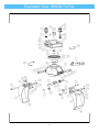
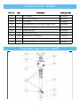
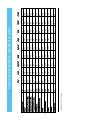
CE Operating and Maintenance Manual Tree Grab Zijtveld Grijpers® Type S 600-B The Netherlands www.zijtveld-grijpers.nl 1 Introduction Dear User, The Tree grab is a piece of equipment for excavators. The Tree grab is available in various weights, capacities and versions and is always a fast and purpose-built selector and demolition device. It is imperative you read this manual and follow all the instructions given when working with our machinery in accordance with our recommendations. The Tree grabs are provided with a CE marking, thereby complying with all the necessary European regulatory safety regulations. It is essential to follow the safety regulations at all times. These safety regulations refer to those laid out in this manual, including both the operating instructions for excavators and the safety regulations that apply to the vicinity in which the Tree grab product is being used, maintained and repaired. Modifications made to the Tree Grab may only be implemented with the written consent of the manufacturer. Only under these circumstances do the warranty conditions and CE liabilities remain applicable. Warning The excavator with a Tree Grab may only be operated by a qualified person. Maintenance and/or repairs may only be carried out by appropriately trained and competent personnel. Prevent dangerous work situations. Stay at a safe distance from moving parts. Ensure that whilst operating the machinery no other people are within the working vicinity of the excavator with tree grab. Maintenance or repair work must only be carried out when the engine is turned off. Refer to the safety regulations before starting on any maintenance or repair work. Replace defective parts only with original parts from the manufacturer. Failure to replace defective parts with original parts from the manufacturer will result in cessation of the entire warranty and CE liability. 2 Index Content Page EU declaration of compliance 4 Safety regulations 5 Conditions of guarantee 7 Operation 8 Daily maintenance 9 Lubrication schedule 10 Exploded view Total 11 Part list Total 1 12 Part list Total 2 13 Partslist + exploded view Cylinder 14 Partslist + exploded view C.O.D. 15 Tightening Torques 16 Technical Specifications 17 ® Zijtveld Grijpers is a registered brand name of Zijtveld Grijpers BV in ‘s- Graveland in the Netherlands. None of the content of this publication may be copied elsewhere without the express permission of Zijtveld Grijpers BV. The manufacturer reserves the right to make alterations or modifications to products and literature at any time. S600B CE MANUAL 20130627v1 UK 3 EU declaration of compliance for machines (Guideline 2006/42/EC) Manufacturer Zijtveld Grijpers B.V. Address De Boomgaard 1 ‘s Graveland The Netherlands Hereby declares that Zijtveld Grijper® Type S600B Serial number meets all the required machine guidelines (Guideline 2006/42/EC, as most recently updated) as well as national legislative implementation of this directive. Attention: Any adjustment that is made to this product without written consent on the manufacturer, makes this declaration void and invalid. We should draw your attention to the fact that the selector grab product is designed to be assembled with another machine, and that the product, on the grounds of the machine Guide Line, can only be used once the whole machine is in accordance to the conditions laid down by European regulations. Signed at ‘s Graveland, Date (signed) 4 Safety Regulations The Tree Grab should always be attached to an excavator of the correct weight, class and capacity of machine. Refer to the data information plate on the grab and consult the technical specifications in this manual. When in doubt contact the supplier. The weight of the grab, increased by the weight of the load being picked up, must never exceed the maximum allowance of lifting power. For further information consult the excavator manual. It is prohibited for people to be within the rotation range of the machine and grab. Keep in mind that material being lifted that extrude from the grab will enlarge the rotation range. It is always possible that material can fall out of the excavator’s grab. For this reason, never rotate the machinery above people, machines nor vehicles. Always pick up a long load at its centre of gravity, to prevent the excavator from either rotating or tipping over. It is not permissible to use the grab to hit or pound. Whilst connecting or disconnecting, lubricating or other maintenance work, the grab must be stable and on a flat surface. Before performing lubricating or other maintenance work the engine should always be shut down. Warning Never work on the hydraulic system if the system is still under pressure! Keep hands away from moving parts at all times. The manufacturer cannot anticipate every possible circumstance that might involve a potential hazard. The warnings in this publication are, therefore, not all–inclusive. If a tool, procedure, work method or operating technique that is not specifically recommended by the manufacturer is used, then you must assure yourself that it is safe for you and others. You should also ensure that the product will not be damaged or made unsafe by the operation, lubrication, maintenance or repair procedures that you choose. 5 Warning Warning: To avoid danger lift a long load only in the center of cravity. 6 Terms of Guarantee The manufacturer provides a warranty of 12 months from the date of delivery. All defective parts proven to be caused by faults in either manufacture, production or material are covered by the warranty. Defective parts that are replaced and fall under guarantee become property of the manufacturer. They must be kept available and returned immediately, in complete and unaltered condition, upon the first request from the manufacturer. Any claim made under guarantee will only be taken into consideration once a written appeal is made to the dealer or manufacturer. This must be done directly after the damage or fault occurs and at least within 24 hours of any irregularities and problems arising. All claims under conditions of the warranty must contain the following data; the type of machine the product has been mounted on, the serial number of the grab, the record of the defective part(s) and a description of the fault, photographs, copy of the delivery papers and invoice and a copy of the invoice of the piece of equipment concerned. Minor repairs can be carried out in consultation with the dealer; the necessary parts which fall under the warrantee, will be delivered without charge. For larger repairs the grab should be sent to your dealer or manufacturer for repairs or modifications. The work and necessary parts are free of charge. However, transport costs and call-out charges to and from your dealer or manufacturer are not covered. The manufacturer is not liable for consequential loss caused by a defective Tree Grab (consequential loss to excavators, consequential loss due to a stationary excavator or the suspending of work activity). Excluded from Guarantee: Damage caused by faulty assembly of a machine and or the hydraulic system, improper maintenance without expertise and transport damage. Defects resulting from improper repairs and/or maintenance including that carried out by an unauthorised third party. Defects arising from neglect or improper execution of preventive maintenance procedures e.g. regular lubrication or greasing. Defects to parts which are subject to normal wear like blades. Consequential loss caused by failure to replace normal wearing parts in time N.B. If defective or worn down parts are replaced by non-original parts, the entire warranty and liability will cease to apply. 7 Procedures to follow before initial use Before taking the machine into operation and to ensure the good functioning of the apparatus, it is important that the following points are checked and correspond to the technical specifications as shown on the information plate and in the manual. The type and weight of the tree grab must conform to weight and machine class of the intended excavator. The oil flow and the pressure for rotating the tree grab should be checked and adjusted. Beware: the return pressure of the rotating oil at a continuous level may be at a maximum of 25 bar, and only briefly (maximum of 10% of the working time) at 100 bar. The oil flow and pressure of the pinching (opening and closing) of the tree grab needs to be controlled and adjusted. Check if the hydraulic quick release hitch is in good order and screwed on firmly. Check if the ball valves and valves are in the correct position Check if the connecting pins between the excavator and the tree grab are well secured, as well as the wedge and the security pin of the quick release hitch system. Ensures that the hoses have the correct length and are at no risk of interfering with any of the moving parts. Also make sure they cannot wear or damage because of contact with the grab or material that is moved by the grab. 8 Daily Maintenance For maintenance work, always place the grab in open position on a flat and stable surface and ensure the excavator cannot move. During maintenance on the hydraulic system the hydraulic hoses need to be disconnected. Before disconnecting ensure there is no pressure on the hoses. Consult the manual for the excavator. The grab must be lubricated once every 8 operating hours with the same lubricant recommended for the excavator. For the position of the grease nipples and frequency of lubrication, see the schedule on page 10. 9 Lubrication Schedule Picture 3: Lubricating cylinder bearing 1 = Lubricate 1 x per 8 operating hours. Picture 4: Lubricating pivoting points 1 = Lubricate 1 x per 8 operating hours. Picture 5: Lubricating rotator 1 = Lubricate 1 x per 8 operating hours. 10 Exploded View S602B-TOTAL 11 Partslist S602B—TOTAL Part nbr. Qty Description 1 1 Welded main frame construction S602B.001 2 1 Shell left (Short lever / small bucket) S602B.002 3 1 Shell right (Long lever / wide bucket) S602B.003 4 1 Welded rotator frame construction S602B.004 5 1 Welded linkage construction S602B.005 6 1 Hydraulic cylinder S602B.006 7 4 Lever support 50mm S602B.007 8 1 Slewing ring S602B.008 9 2 Main hinge pin S602B.009 10 1 Linkage axis Ø60mm (top / long) S602B.010 11 1 Linkage axis Ø50mm (under / short) S602B.011 12 2 Disk spring S602B.012 13 2 Castellated nut M42 S602B.013 14 2 Spline pin 8 mm x 60 (secure on M42) S602B.014 15 2 Locking pin 16 mm S602B.015 16 1 Linkage axis (top) Ø 60mm S602B.016 17 1 Bearing Linkage S602B.017 18 1 Bearings shell hinge short S602B.018 19 4 Bearings main frame S602B.019 20 9 O-ring Metal Seal S602B.020 21 9 Metal Seal Ø106mm S602B.021 22 1 Shell hinge short S602B.022 23 2 Shell hinge long S602B.023 24 3 Shell hinge support S602B.024 25 1 Fixed blade left bucket (small) S602B.025 26 1 Fixed balde right bucket (wide) S602B.026 27 1 set Seal (2 pieces) S602B.027 28 1 set Hose Set Lower frame (2 pieces) S602B.028 29 1 V-ring (central ring) S602B.029 12 Order part nbr. Partslist S602B—TOTAL Part nbr. Qty Description 30 1 set Allen screw / nut (16 / 16 pieces) S602B.030 31 1 set Lubrication nipple 1/8”G (13 pieces) S602B.031 32 1 Connector block Ø 60 mm (50x40x70mm) S602B.032 33 1 set 0-ring connector block c.o.d. Ø 60mm (2 pcs.) S602B.033 34 1 set Allenscrew COD Connector block (2 pieces) S602B.034 35 2 Protective cover (connection nipples) S602B.035 36 2 Main-connect block (closing/open) function 3/4"G S602B.036 37 2 Main-connect nipple (closing/open function) S602B.037 38 2 Main-connect block (rotation function) 1/2"G S602B.038 39 2 Main-connect nipple (rotation function) S602B.039 40 2 Hydro-valve S602B.040 41 2 Gear S602B.041 42 1 set Seal kit to Hydraulic motor (for 1 motor) S602B.042 43 1 set Allen Screw / ring (8 pieces) S602B.043 44 1 C.o.d. Complete S602B.044 45 1 set Allen screw C.o.d. (2 pcs) S602B.045 46 1 set Hose kit set head (6 pcs) S602B.046 47 1 Locker-U S602B.047 48 1 0-ring metal seal S602B.048 49 1 Metal seal (Ø 120 mm) S602B.049 13 Order partn br. Partslist Cylinder S602B Part nbr. Qty Description Order part nbr. 101 1 Cylinder housing S602B.101 102 1 Piston Rod S602B.102 103 1 Cylinder Head S602B.103 104 1 Piston S602B.104 105 1 Bearing Cylinder Housing S602B.105 106 1 Plain Bearing cylinder nut S602B.106 107 1set Cylinder seal-kit S602B.107 108 1 Secure bolt M8 x12 S602B.108 109 1 Secure bolt M6 x 6 S602B.109 110 1set Cylinder nipple-set (2 pcs.) S602B.110 111 1 Bearing Cylinder Piston S602B.111 Exploded view Cylinder S602B 14 Partslist C.O.D. S602B Part nbr. Qty Description 201 1 C.o.d. housing S602B.201 202 1 C.o.d. rotor Ø 60mm S602B.202 203 1 C.o.d. cover S602B.203 204 1 Connection Block C.o.d. Ø 60mm (50x40x70mm) S602B.204 205 1 Bearing S602B.205 206 1 Seeger circlip ring S602B.206 207 1set Allen screw kit (2 pcs) S602B.207 208 1set Rotor Seal kit c.o.d. Ø60mm S602B.208 209 1set Connection nipples c.o.d. housing (2 pcs) S602B.209 210 1set Connection nipples c.o.d. connection block (2 pcs) S602B.210 Exploded view C.O.D. S602B 15 Order part nbr. Torques Specification Maximum torque specified to bolts on the blades and rotator of the Zijtveld Tree grab. Please consult this listing on diameter, pitch and metric size and maximum torque specified prior to fastening. Bolt size Torque (Nm) Torque (Kg/m) Bolt 10,9 Bolt 10,9 M8 40 Nm 4 Kgm M10 80 Nm 8 Kgm M12 130 Nm 13 Kgm M12x1,25 110 Nm 11 Kgm M14 200 Nm 20 Kgm M16 300 Nm 30 Kgm M20 600 Nm 60 Kgm M24 1000 Nm 100 Kgm M27 1500 Nm 150 Kgm M30 2000 Nm 200 Kgm M36 3600 Nm 360 Kgm M39 4600 Nm 460 Kgm 16 Note ,fine pitch. 17 kg bar bar bar l/min. l/min. mm mm mm ltr. kn Weight Operating Pressure Max. Operating Pressure Min. Pressure Rotation max. Oil flow max. Oil flow Rotation max. Width Spread openend Height Content Closing Force Specifications subject to change tons Class excavator 10 Ø50 700 1100 450 10 30 210 170 300 145 1,5 — 4 150B 20 Ø50 900 1600 530 12 40 210 140 300 350 4—8 400B 20 Ø50 900 1600 750 12 40 210 140 300 420 4—9 450B-5T 2020 Ø60 900 1600 750 12 40 210 140 300 470 7 — 11 452B 35 Ø100 1300 2000 600 25 100 210 190 350 900 10 — 16 600B-9T 35 Ø150 1300 2000 600 25 100 210 190 350 800 10 — 16 600B 40 Ø150 1400 2000 750 25 120 210 190 350 960 14 — 20 902B Technical specifications : Zijtveld Tree grabs 60 Ø200 1450 2300 900 35 170 210 190 350 1500 18 — 30 1202B 80 Ø230 1900 2900 1200 40 250 210 190 350 2850 30 — 50 2700B