1
2-5
Set Up the Hardware
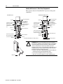
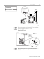
1 Define the DH+ Station Address of Channel 1A
by setting switch assembly SW-1 on the back of
the processor. (See the side of the processor if
you want to use another address.)
Locking Bar
side view of processor
Lift Ejector Tab
PLC-5/20
Processor
1 2 3 4 5 6 7
Battery Connector
Battery Cover
side view
down
57.6 Kbaud
For series E and later processors:
use this switch to select baud rate
For series D and earlier processors:
this switch is always off
up
230 Kbaud
Card Guides
20610-M
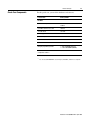
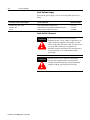
2 Specify the digital interface of channel 0.
bottom view of PLC-5/20C processor
Battery
Front of
Processor
More
For detailed information about handling and disposing of the battery
as well as other important guidelines, see publication AG-5.4.
1 2 3 4 5 6 7 8 9 10
More
For more information, see the ControlNet PLC-5 Programmable
Controllers User Manual, publication number 1785-UM022.
bottom view of PLC-5/40C and -5/80C processor
Front of
Processor
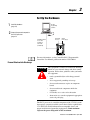
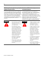
WARNING
!
When you connect or disconnect the battery,
an electrical arc can occur. This could cause an
explosion in hazardous location installations.
Be sure that power is removed or the area is
nonhazardous before proceeding. For safety
information on the handling of lithium batteries,
including handling and disposal of leaking batteries,
see Guidelines for Handling Lithium Batteries,
publication AG-5.4.
side view
1 2 3 4 5 6 7 8 9 10
OFF
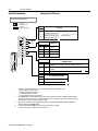
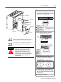
3 Set the ControlNet network addresses by
using the two 10-digit rotary switches on
top of the module.
ControlNet PLC-5 processor's NET address = 1
20
30
10
2
00
50
60
90
80
70
3
1
40
4
0
5
9
6
8
7
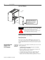
4 To install the battery, slide the battery-side
connector into the processor-side connector
until you hear them snap together, and attach
the battery cover.
5 Install the processor module.
Publication 1785-QS006C-EN-P - April 2002