1
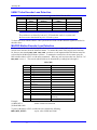
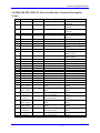
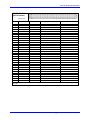
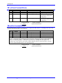
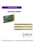
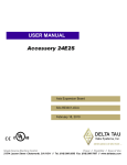
^1 USER MANUAL
^2 ACCESSORY 2E
^3 4-Axis Expansion Board
^4 3Ax-602805-xUxx
^5 October 15, 2003
Single Source Machine Control
Power // Flexibility // Ease of Use
21314 Lassen Street Chatsworth, CA 91311 // Tel. (818) 998-2095 Fax. (818) 998-7807 // www.deltatau.com
Copyright Information
© 2003 Delta Tau Data Systems, Inc. All rights reserved.
This document is furnished for the customers of Delta Tau Data Systems, Inc. Other uses are
unauthorized without written permission of Delta Tau Data Systems, Inc. Information contained
in this manual may be updated from time-to-time due to product improvements, etc., and may not
conform in every respect to former issues.
To report errors or inconsistencies, call or email:
Delta Tau Data Systems, Inc. Technical Support
Phone: (818) 717-5656
Fax: (818) 998-7807
Email: [email protected]
Website: http://www.deltatau.com
Operating Conditions
All Delta Tau Data Systems, Inc. motion controller products, accessories, and amplifiers contain
static sensitive components that can be damaged by incorrect handling. When installing or
handling Delta Tau Data Systems, Inc. products, avoid contact with highly insulated materials.
Only qualified personnel should be allowed to handle this equipment.
In the case of industrial applications, we expect our products to be protected from hazardous or
conductive materials and/or environments that could cause harm to the controller by damaging
components or causing electrical shorts. When our products are used in an industrial
environment, install them into an industrial electrical cabinet or industrial PC to protect them
from excessive or corrosive moisture, abnormal ambient temperatures, and conductive materials.
If Delta Tau Data Systems, Inc. products are directly exposed to hazardous or conductive
materials and/or environments, we cannot guarantee their operation.
Accessory 2E
Table of Contents
OVERVIEW ..................................................................................................................................................1
Features .......................................................................................................................................................1
Power Requirements ...................................................................................................................................1
CONNECTOR SUMMARY .........................................................................................................................3
ACC-2E Four-Axis Piggyback Board .........................................................................................................3
ACC-2E FOUR-AXIS PIGGYBACK BOARD JUMPERS.......................................................................5
ACC-2E OUTPUT MODE............................................................................................................................7
UMAC Turbo Outputs ................................................................................................................................7
Direct PWM Mode for UMAC Turbo .....................................................................................................7
DAC Output Mode for UMAC Turbo......................................................................................................7
PFM Output Mode for UMAC Turbo .....................................................................................................8
MACRO Outputs.........................................................................................................................................8
Direct PWM Mode for MACRO..............................................................................................................8
DAC Output Mode for MACRO..............................................................................................................8
PFM Output Mode for MACRO..............................................................................................................9
ENCODER LOSS FEATURE ....................................................................................................................10
Principle of Operation ...............................................................................................................................10
UMAC Turbo Encoder Loss Detection .....................................................................................................11
MACRO Station Encoder Loss Detection.................................................................................................11
ACC-2E 4-AXIS PIGGYBACK BOARD CONNECTOR DESCRIPTION ..........................................14
J1-J3 (JEXP_A - JEXP_C) (For Interboard Connection)..........................................................................14
J4 (JMACH1-DIG) PMAC2-Style Axis Interface Connector Description ...............................................14
J5 (JMACH2-DIG) PMAC2-Style Axis Interface Connector Description ...............................................18
P1 (JMACH-ANA) PMAC(1)-Style Axis Interface Connector Description.............................................22
P1 JMACH-ANA (96-Pin Header)........................................................................................................22
TB1 (4-Point Terminal Block) ..................................................................................................................25
TB2 (4-Pin Terminal Block) .....................................................................................................................25
Table of Contents
i
Accessory 2E
ii
Table of Contents
Accessory 2E
OVERVIEW
The ACC-2E Axis Expansion Board provides two or four channels of PMAC2-style servo interface
circuitry for UMAC-Turbo and Ultralite/MACRO Station controllers. The ACC-2E is part of the UMAC
or MACRO Stack family of expansion cards and these accessory cards are designed to plug into an
industrial 3U rack system. The information from these accessories is passed directly to either the UMAC
or MACRO Station CPU via the high speed JEXP expansion bus.
Up to two ACC-2E boards can be connected to one UMAC, providing up to 8 channels of servo interface
circuitry for either the UMAC-Turbo or UMAC-MACRO systems.
The ACC-2E board contains no processor; it has 1 highly integrated 4-channel PMAC2-style “Servo IC”
with the buffering circuitry and connectors around them. The ACC-2E stacks into either the 3U Turbo
PMAC or the MACRO CPU cards, and uses one slot in the rack.
The ACC-2E provides four channels of PMAC2-style digital servo interface through two 100-pin highdensity JMACH connectors; breakout supported through PMAC2-style ACC-8 boards (sine-wave drives
can be supported through ACC-8E). Up to two ACC-2E boards are permitted in a Compact MACRO
Station configuration.
With ACC-2E option A, the on-board 4 channels of analog output, 4 sets of flag isolation, and PMAC(1)style interface through 96-pin DIN connector. Pinout like PMAC(1)-VME; breakout supported through
ACC-8D or ACC-8P with Option V cable.
Note
The ACC-2E was not designed to plug into the Delta Tau UBUS Systems
Features
The ACC-2E board can be used with any UMAC or MACRO Station CPU, interfacing through the stack
JEXP connector.
The ACC-2E supports a wide variety of servo and stepper interfaces:
•
•
•
•
•
Analog +/-10V velocity commands
Analog +/-10V torque commands
Sinusoidal analog +/-10V phase current commands
Direct PWM phase current commands
Pulse-and-direction commands
Power Requirements
5V
12V*
750mA
400mA
* with option 1A
Overview
-12V*
400mA
other 24V etc.
N/A
1
Accessory 2E
2
Overview
Accessory 2E
CONNECTOR SUMMARY
ACC-2E Four-Axis Piggyback Board
J1: (JEXP_A) 40-pin header for connection to piggyback board(s)
J2: (JEXP_B) 40-pin header for connection to piggyback board(s)
J3: (JEXP_C) 28-pin header for connection to piggyback board(s)
J4: (JMACH1_DIG) 100-pin high-density connector for 2-axis servo connection (Channels 1 & 2) to
PMAC2-style ACC-8x breakout boards or equivalent
J5: (JMACH2_DIG) 100-pin high-density connector for 2-axis servo connection (Channels 3 & 4) to
PMAC2-style ACC-8x breakout boards or equivalent
P1: (JMACH_ANA) 96-pin DIN connector for servo connection to PMAC(1)-style ACC-8D/*P breakout
boards or equivalent. Only present if Option A ordered.
TB1: (JWDO): 4-point terminal block for output of watchdog-timer hard-contact relay.
Connector Summary
3
ACC-2E Axis Expansion Board
4
Connector Summary
Accessory 2E
ACC-2E FOUR-AXIS PIGGYBACK BOARD JUMPERS
E1: Channel Select
Jump pins 1 and 2 to select board as Channels 1-4.
Jump pins 2 and 3 to select board as Channels 5-8
Note:
If two four-axis piggyback boards are used on a Compact MACRO Station, they
must have different settings of this jumper.
E2: Handwheel Input Source Select
Remove jumper to permit handwheel encoder inputs on P1 B-row of this board.
Jump pins 1 and 2 to permit use of encoder inputs from 2-axis board.
E3: Serial ADC Data Source Select
Remove jumper to permit use of ADC serial inputs from 2-axis board.
Jump pins 1 and 2 to permit use of ADC serial inputs on P1 B-row.
E4: Channel 1 Flag Source Select
Jump pins 1 and 2 to use input flags from J4 PMAC2-style connector.
Jump pins 2 and 3 to use input flags from P1 PMAC(1)-style connector.
E5: Channel 2 Flag Source Select
Jump pins 1 and 2 to use input flags from J4 PMAC2-style connector.
Jump pins 2 and 3 to use input flags from P1 PMAC(1)-style connector.
E6: Channel 3 Flag Source Select
Jump pins 1 and 2 to use input flags from J4 PMAC2-style connector.
Jump pins 2 and 3 to use input flags from P1 PMAC(1)-style connector.
E7: Channel 4 Flag Source Select
Jump pins 1 and 2 to use input flags from J4 PMAC2-style connector.
Jump pins 2 and 3 to use input flags from P1 PMAC(1)-style connector.
E17A: AENA1 Polarity Select (Option A only)
Remove jumper for high-true AENA1 signal on P1.
Jump pins 1 and 2 for low-true AENA1 signal on P1.
E17B: AENA2 Polarity Select (Option A only)
Remove jumper for high-true AENA2 signal on P1.
Jump pins 1 and 2 for low-true AENA2 signal on P1.
E17C: AENA3 Polarity Select (Option A only)
Remove jumper for high-true AENA3 signal on P1.
Jump pins 1 and 2 for low-true AENA3 signal on P1.
E17D: AENA4 Polarity Select (Option A only)
Remove jumper for high-true AENA4 signal on P1.
Jump pins 1 and 2 for low-true AENA4 signal on P1.
E87: Flag Return Voltage Control (Option A only)
Remove jumper to separate FRET from signal common (GND) on board. (Must supply
external FRET: +12V to +24V for sinking flag drivers)
Jump pins 1 and 2 to tie FRET to signal common on board. (Must tie E90 1-2 and use
sourcing flag drivers)
ACC-2E Four-Axis Piggyback Board Jumpers
5
ACC-2E Axis Expansion Board
E90: Flag Return Source Control (Option A only)
Jump pins 1 and 2 to use FRET or GND (see E87) as flag return voltage.
Jump pins 2 and 3 to use analog A+15V supply as flag return voltage.
(Must use sinking flag drivers)
E101: AENA/EQU Sinking/Sourcing Output Select (Option A only)
CAUTION:
Wrong jumper setting will damage IC.
Jump pins 1 and 2 for ULN2803A sinking driver IC in U2 for AENA & EQU.
Jump pins 2 and 3 for UDN2981A sourcing driver IC in U2 for AENA & EQU.
E102: AENA/EQU Sinking/Sourcing Output Select (Option A only)
CAUTION:
Wrong jumper setting will damage IC.
Jump pins 1 and 2 for ULN2803A sinking driver IC in U2 for AENA & EQU.
Jump pins 2 and 3 for UDN2981A sourcing driver IC in U2 for AENA & EQU.
E111: Channel 1 Output Signal Disable Control
Jump pins 1 and 2 to tri-state digital command output signals on amplifier disable.
Remove jumper to leave active zero-value digital command output signals on amplifier disable.
E112: Channel 2 Output Signal Disable Control
Jump pins 1 and 2 to tri-state digital command output signals on amplifier disable.
Remove jumper to leave active zero-value digital command output signals on amplifier disable.
E113: Channel 3 Output Signal Disable Control
Jump pins 1 and 2 to tri-state digital command output signals on amplifier disable.
Remove jumper to leave active zero-value digital command output signals on amplifier disable.
E114: Channel 4 Output Signal Disable Control
Jump pins 1 and 2 to tri-state digital command output signals on amplifier disable.
Remove jumper to leave active zero-value digital command output signals on amplifier disable.
6
ACC-2E Four-Axis Piggyback Board Jumpers
Accessory 2E
ACC-2E OUTPUT MODE
The ACC-2E has three modes of outputs which are setup by either the TURBO UMAC or the MACRO
CPU. The output modes available for the ACC-2E are Direct PWM, DAC, or PFM.
UMAC Turbo Outputs
To setup the output mode for the UMAC Turbo the user must set I7mn6 to the proper value. The Gate
Array on the ACC-2E has three outputs per channel as shown below:
I7mn6
Setting
A Output
B Output
C Output
I7mn6=0
I7mn6=1
I7mn6=2
I7mn6=3
PWM
DAC
PWM
DAC
PWM
DAC
PWM
DAC
PWM
PWM
PFM
PFM
Direct PWM Mode for UMAC Turbo
To setup Direct PWM outputs the user will set I7mn6 equal to zero. Direct PWM outputs would typically
be used with the Delta Tau ACC-8F. The PMAC2 gate array on the ACC-2E would put the A, B, and C
outputs into PWM mode. Typical settings for direct PWM outputs are shown below.
Channel
Setting
Channel
Setting
1
2
3
4
I7016=0
I7026=0
I7036=0
I7046=0
5
6
7
8
I7116=0
I7126=0
I7136=0
I7146=0
DAC Output Mode for UMAC Turbo
To setup Direct PWM outputs the user will set I7mn6 equal to one or three. DAC outputs would typically
be used with the ACC-2E Option 1A or the Delta Tau ACC-8A or ACC-8E. The PMAC2 gate array on
the ACC-2E would put the A and B outputs into DAC mode. Typical settings for direct DAC outputs are
shown below.
Channel
Setting
Channel
Setting
1
2
3
4
I7016=3
I7026=3
I7036=3
I7046=3
5
6
7
8
I7116=3
I7126=3
I7136=3
I7146=3
When used with the ACC-2E Option1A the user must modify the DAC strobe word for proper
operation. The DAC Strobe word must set to $7FFF0 for 16-bit DACs on the ACC-2E option 1A. The
default setting for the DAC Strobe word is for 18-bit operation.
ACC-2E Option 1A
ACC-8E or ACC-8A
Channels
Setting
Channels
Setting
1-4
5-8
I7005=$7FFF00
I7105=$7FFF00
1-4
5-8
I7005=$7FFFC0
I7105=$7FFFC0
ACC-2E Four-Axis Piggyback Board Jumpers
7
ACC-2E Axis Expansion Board
PFM Output Mode for UMAC Turbo
To setup Direct PWM outputs the user will set I7mn6 equal to two or three. DAC outputs would
typically be used with the Delta Tau ACC-8S. The PMAC2 gate array on the ACC-2E would put the C
output into PFM mode. Typical settings for direct DAC outputs are shown below.
Channel
Setting
Channel
Setting
1
2
3
4
I7016=3
I7026=3
I7036=3
I7046=3
5
6
7
8
I7116=3
I7126=3
I7136=3
I7146=3
MACRO Outputs
To setup the output mode for the MACRO the user must set MSn,MI916 to the proper value. The Gate
Array on the ACC-2E has three outputs per channel as shown below:
MI916
Setting
A
Output
B
Output
C
Output
MI916=0
MI916=1
MI916=2
MI916=3
PWM
DAC
PWM
DAC
PWM
DAC
PWM
DAC
PWM
PWM
PFM
PFM
Direct PWM Mode for MACRO
To setup Direct PWM outputs the user will set MI916 equal to zero. Direct PWM outputs would
typically be used with the Delta Tau ACC-8F. The PMAC2 gate array on the ACC-2E would put the A,
B, and C outputs into PWM mode. Typical settings for direct PWM outputs are shown below.
Channel
Setting
Channel
Setting
1
2
3
4
MS0,MI916=0
MS1,MI916=0
MS4,MI916=0
MS5,MI916=0
5
6
7
8
MS8,MI916=0
MS9,MI916=0
MS12,MI916=0
MS13,MI916=0
DAC Output Mode for MACRO
To setup Direct PWM outputs the user will set MI916 equal to one or three. DAC outputs would
typically be used with the ACC-2E Option 1A or the Delta Tau ACC-8A or ACC-8E. The PMAC2 gate
array on the ACC-2E would put the A and B outputs into DAC mode. Typical settings for direct DAC
outputs are shown below.
8
Channel
Setting
Channel
Setting
1
2
3
4
MS0,MI916=3
MS1,MI916=3
MS4,MI916=3
MS5,MI916=3
5
6
7
8
MS8,MI916=3
MS9,MI916=3
MS12,MI916=3
MS13,MI916=3
ACC-2E Four-Axis Piggyback Board Jumpers
Accessory 2E
Depending on the type of interface card the user is using for their DAC ouputs, the DAC strobe word
might have to be modified for proper operation. The DAC Strobe word must set to $7FFF00 for 16-bit
DACs on the ACC-1E option 1A (default) and it must be set to $7FFFC0 for 18-bit operation if used with
the ACC-8E or ACC-8A.
ACC-2E Option 1A
ACC-8E or ACC-8A
Channels
Setting
Channels
Setting
1-4
5-8
MS0,MI905=$7FFF00
MS0,MI909=$7FFF00
1-4
5-8
MS0,MI905=$7FFFC0
MS0,MI909=$7FFFC0
PFM Output Mode for MACRO
To setup Direct PWM outputs the user will set MI916 equal to two or three. DAC outputs would
typically be used with the Delta Tau ACC-8S. The PMAC2 gate array on the ACC-2E would put the C
output into PFM mode. Typical settings for direct DAC outputs are shown below.
Channel
Setting
Channel
Setting
1
2
3
4
MS0,MI916=3
MS1,MI916=3
MS4,MI916=3
MS5,MI916=3
5
6
7
8
MS8,MI916=3
MS9,MI916=3
MS12,MI916=3
MS13,MI916=3
ACC-2E Four-Axis Piggyback Board Jumpers
9
ACC-2E Axis Expansion Board
ENCODER LOSS FEATURE
Many newer PMAC and UMAC systems have dedicated circuitry for the detection of the loss of
incremental encoder feedback. However, there is presently no dedicated firmware function to take action
when loss of encoder is detected.
Principle of Operation
The encoder-loss detection circuitry works only for differential incremental encoders. In proper
operation, the digital states of the complementary inputs for a channel (e.g. A and A/) should always be
opposite: when one is high, the other is low. If for some reason, such as a cable connection coming
undone, one or more of the signal lines is no longer driven, pull-up resistors on the input line pull and
hold the signal high.
The encoder-loss detection circuitry uses “exclusive-or” (XOR) gates on each complementary pair to
detect whether the signals are in the same or opposite states. These results are combined to produce a
single “encoder-loss” status bit that the processor can read.
In order to enable this function, the socketed resistor packs for the encoder must be reversed from their
factory default setting so that the complementary encoder lines A/, B/, and C/ are pulled up to 5V instead
of pulled to 2.5V. The resistor packs to be reversed are RP28, RP29, RP30, and RP31.
RP30 – Channel 1
RP31 – Channel 2
RP28 – Channel 3
RP29 – Channel 4
The resistor packs are located near the JMACH connectors on the ACC-2E and the ACC-1E as shown in
the diagram below.
10
ACC-2E Four-Axis Piggyback Board Jumpers
Accessory 2E
UMAC Turbo Encoder Loss Detection
ACC-2E Discrete On-board Logic with UMAC Turbo CPU
Channel
Resistor
Pack
Status Bit
Address*
Status Bit
“Name”
Bit Error State
1
2
3
4
RP30
RP31
RP28
RP29
Y:$078403,8
Y:$078403,9
Y:$078403,10
Y:$078403,11
CTRL0
CTRL1
CTRL2
CTRL3
0
0
0
0
Note
These addresses are shared by both ACC-2E boards that can be in a system, and
the first two are shared with any ACC-1E in the system.
To detect the errors with the UMAC Turbo system the user must read the status bit registers described in
the table above.
MACRO Station Encoder Loss Detection
To detect the encoder loss with the MACRO-Station, the user must set MSn,MI7=1 and monitor the
encoder error detection bit at the MACRO-Station. To monitor the status of the encoder error detection
bit, the user must monitor MSn,MI4. MSn,MI4 monitors several important MACRO Station status bits
as described in the MACRO Software reference. To monitor the encoder loss, the user must query the
MI4 variable either in a PLC or with online commands. When any axis has an encoder loss, then bit 5 of
MSn,MI4 is set to 1. The encoder which failed can be determined by reading bits 8 through 11.
MSn, MI4
Bit #
0
1
2
3
4
5
6
7
8
9
10
11
12
13
13-23
Example:
(a) MS0, MI7=1
(b) Read MS0, MI4
Fault
CPU Fault
Ring Communications Error
Ring Break Detected
Station Fault
Ring Fault
Encoder-Loss Fault
Amplifier Fault
Ring Break Notification
Received
Encoder 1 or 5 Loss Fault
Encoder 2 or 6 Loss Fault
Encoder 3 or 7 Loss Fault
Encoder 4 or 8 Loss Fault
Ring Active
Multiplexer Port Parity Error
Notes
From ACC-34 board with parity
checking
(Reserved for future use)
;enable encoder loss detection
To process the data in a PLC or online the user could do the following:
MSR,MI4,P1000
;copies value of MI4 into P1000
ACC-2E Four-Axis Piggyback Board Jumpers
11
ACC-2E Axis Expansion Board
To Read bit 5 of MS0, MI4
P800=P1000&$0020/$20
;if P800=1, we have an encoder loss at the MACRO Station
To Read bit 8 of MS0, MI4
P801=P1000&$0100/$100 ;if P801=1, we have an encoder loss on encoder 1 or 5
To Read bit 9 of MS0, MI4
P802=P1000&$0200/$200 ;if P802=1, we have an encoder loss on encoder 2 or 6
To Read bit 10 of MS0, MI4
P803=P1000&$0400/$400 ;if P803=1, we have an encoder loss on encoder 3 or 7
To Read bit 11 of MS0, MI4
P804=P1000&$0800/$800 ;if P804=1, we have an encoder loss on encoder 4 or 8
When a loss of encoder is detected, the MACRO-Station will display an “E”.
12
ACC-2E Four-Axis Piggyback Board Jumpers
Accessory 2E
ACC-2E Four-Axis Piggyback Board Jumpers
13
ACC-2E Axis Expansion Board
ACC-2E 4-AXIS PIGGYBACK BOARD CONNECTOR
DESCRIPTION
J1-J3 (JEXP_A - JEXP_C) (For Interboard Connection)
(Consult factory if pinout information needed.)
J4 (JMACH1-DIG) PMAC2-Style Axis Interface Connector Description
14
Pin#
Symbol
Function
Description
Notes
1
+5V
Output/Input
+5V Power
2
+5V
Output/Input
+5V Power
For external circuit or from
external supply
For external circuit or from
external supply
3
4
5
6
7
8
9
10
11
GND
GND
CHA1+
CHA1CHB1+
CHB1CHC1+
CHC1CHU1
Common
Common
Input
Input
Input
Input
Input
Input
Input
12
CHV1
Input
Channel 1 V Flag
13
CHW1
Input
Channel 1 W Flag
14
15
CHT1
USER1
Input
Input
Channel 1 T Flag
General Purpose User Flag
16
17
18
19
PLIM1
MLIM1
HOME1
ACCFLT1
Input
Input
Input
Input
Positive Overtravel Limit
Negative Overtravel Limit
Home Switch Input
Accessory Fault Flag
20
WD0/
Output
21
SCLK12+
Input/Output
Encoder Sample Clock
22
SCLK12-
Input/Output
Encoder Sample Clock
23
24
25
26
27
28
ADC_CLK1+
ADC_CLK1ADC_STB1+
ADC_STB1ADC_DAA1+
ADC_DAA1-
Output
Output
Output
Output
Input
Input
Reference Voltage
Reference Voltage
Encoder 1 Positive A Channel
Encoder 1 Negative A Channel
Encoder 1 Positive B Channel
Encoder 1 Negative B Channel
Encoder 1 Positive C Channel
Encoder 1 Negative C Channel
Channel 1 U Flag
Watchdog Output
A/D Converter Clock
A/D Converter Clock
A/D Converter Strobe
A/D Converter Strobe
Channel A ADC Serial Data
Channel A ADC Serial Data
Also pulse input
Also pulse input
Also direction input
Also direction input
Index channel
Index channel
Hall Effect, Fault Code, or
sub-count
Hall Effect, Fault Code, or
sub-count
Hall Effect, Fault Code, or
sub-count
Fault Code, or sub-count
Hardware capture flag, or
sub-count
Hardware capture flag
Hardware capture flag
Hardware capture flag
For loss of ACC supply
voltage
Low is PMAC watchdog
fault
Direction controlled by
PMAC2 jumper
Direction controlled by
PMAC2 jumper
Programmable frequency
Programmable frequency
Programmable sequence
Programmable sequence
MSB first
MSB first
ACC-2E Four-Axis Piggyback Board Connector Descriptions
Accessory 2E
J4 (JMACH1-DIG) PMAC2-Style Axis Interface Connector Description
(Cont.)
Pin#
Symbol
Function
Description
29
30
31
32
33
34
35
Input
Input
Output
Output
Input
Input
Output
47
48
49
ADC_DAB1+
ADC_DAB1AENA1+
AENA1FAULT1+
FAULT1PWMATOP1+
DAC_CLK1+
PWMATOP1DAC_CLK1PWMABOT1+
DAC1A+
PWMABOT1DAC1APWMBTOP1+
DAC_STB1+
PWMBTOP1DAC_STB1PWMBBOT1+
DAC1B+
PWMBBOT1DAC1BPWMCTOP1+
DIR1+
PWMCTOP1DIR1PWMCBOT1+
PULSE1+
PWMCBOT1PULSE1GND
GND
+5V
Common
Common
Output/Input
Channel B ADC Serial Data
Channel B ADC Serial Data
Amplifier Enable
Amplifier Enable
Amplifier Fault
Amplifier Fault
Phase A Top CMD or DAC
Clock
Phase A Top CMD or DAC
Clock
Phase A Bottom CMD or DAC
A Serial Data
Phase A Bottom CMD or DAC
A Serial Data
Phase B Top CMD or DAC
Strobe
Phase B Top CMD or DAC
Strobe
Phase B Bottom CMD or DAC
B Serial Data
Phase B Bottom CMD or DAC
B Serial Data
Phase B Top CMD or PFM
Direction
Phase B Top CMD or PFM
Direction
Phase B Bottom CMD or PFM
Pulse
Phase B Bottom CMD or PFM
Pulse
Reference Voltage
Reference Voltage
+5V Power
50
+5V
Output/Input
+5V Power
51
+5V
Output/Input
+5V Power
52
+5V
Output/Input
+5V Power
53
54
55
56
57
58
59
60
GND
GND
CHA2+
CHA2CHB2+
CHB2CHC2+
CHC2-
Common
Common
Input
Input
Input
Input
Input
Input
36
37
38
39
40
41
42
43
44
45
46
Output
Output
Output
Output
Output
Output
Output
Output
Output
Output
Output
Reference Voltage
Reference Voltage
Encoder 2 Positive A Channel
Encoder 2 Negative A Channel
Encoder 2 Positive B Channel
Encoder 2 Neg. B Channel
Encoder 2 Positive C Channel
Encoder 2 Neg. C Channel
ACC-2E Four-Axis Piggyback Board Connector Descriptions
Notes
MSB first
MSB first
High is enable
Low is enable
Programmable polarity
Programmable polarity
Programmable function
control
Programmable function
control
Programmable function
control
Programmable function
control
Programmable function
control
Programmable function
control
Programmable function
control
Programmable function
control
Programmable function
control
Programmable function
control
Programmable function
control
Programmable function
control
For external circuit or from
external supply
For external circuit or from
external supply
For external circuit or from
external supply
For external circuit or from
external supply
Also Pulse input
Also Pulse input
Also direction input
Also direction input
Index channel
Index channel
15
ACC-2E Axis Expansion Board
J4 (JMACH1-DIG) PMAC2-Style Axis Interface Connector Description
(Cont.)
Pin#
Symbol
Function
61
CHU2
Input
Channel 2 U Flag
62
CHV2
Input
Channel 2 V Flag
63
CHW2
Input
Channel 2 W Flag
64
65
CHT2
USER2
Input
Input
Channel 2 T Flag
General Purpose User Flag
66
67
68
69
PLIM2
MLIM2
HOME2
ACCFLT2
Input
Input
Input
Input
Positive Overtravel Limit
Negative Overtravel Limit
Home Switch Input
Accessory Fault Flag
70
71
WD0/
SCLK12+
Output
Input/Output
Watchdog Output
Encoder Sample Clock
72
SCLK12-
Input/Output
Encoder Sample Clock
73
74
75
76
77
78
79
80
81
82
83
84
85
ADC_CLK2+
ADC_CLK2ADC_STB2+
ADC_STB2ADC_DAA2+
ADC_DAA2ADC_DAB2+
ADC_DAB2AENA2+
AENA2FAULT2+
FAULT2PWMATOP2+
DAC_CLK2+
PWMATOP2DAC_CLK2PWMABOT2+
DAC2A+
PWMABOT2DAC2APWMBTOP2+
DAC_STB2+
PWMBTOP2DAC_STB2PWMBBOT2+
DAC2B+
PWMBBOT2DAC2B-
Output
Output
Output
Output
Input
Input
Input
Input
Output
Output
Input
Input
Output
86
87
88
89
90
91
92
16
Output
Output
Output
Output
Output
Output
Output
Description
A/D Converter Clock
A/D Converter Clock
A/D Converter Strobe
A/D Converter Strobe
Channel A ADC Serial Data
Channel A ADC Serial Data
Channel B ADC Serial Data
Channel B ADC Serial Data
Amplifier Enable
Amplifier Enable
Amplifier Fault
Amplifier Fault
Phase A Top CMD or DAC
Clock
Phase A Top CMD or DAC
Clock
Phase A Bottom CMD or
DAC A Serial Data
Phase A Bottom CMD or
DAC A Serial Data
Phase B Top CMD or DAC
Strobe
Phase B Top CMD or DAC
Strobe
Phase B Bottom CMD or
DAC B Serial Data
Phase B Bottom CMD or
DAC B Serial Data
Notes
Hall Effect, Fault Code, or
SUB-count
Hall EFFECT, Fault Code, or
sub-count
Hall EFFECT, Fault Code, or
sub-count
Fault Code, or sub-count
Hardware capture flag, or
sub-count
Hardware capture flag
Hardware capture flag
Hardware capture flag
For loss of Acc supply
voltage
Low is PMAC watchdog fault
Direction controlled by
PMAC2 jumper
Direction controlled by
PMAC2 jumper
Programmable frequency
Programmable frequency
Programmable sequence
Programmable sequence
MSB first
MSB first
MSB first
MSB first
High is enable
Low is enable
Programmable polarity
Programmable polarity
Programmable function
control
Programmable function
control
Programmable function
control
Programmable function
control
Programmable function
control
Programmable function
control
Programmable function
control
Programmable function
control
ACC-2E Four-Axis Piggyback Board Connector Descriptions
Accessory 2E
J4 (JMACH1-DIG) PMAC2-Style Axis Interface Connector Description
(Cont.)
Pin#
Symbol
Function
93
PWMCTOP2+
DIR2+
PWMCTOP2DIR2PWMCBOT2+
PULSE2+
PWMCBOT2PULSE2GND
GND
+5V
Output
94
95
96
97
98
99
Output
Output
Output
Common
Common
Output/Input
Description
Phase B Top CMD or PFM
Direction
Phase B Top CMD or PFM
Direction
Phase B Bottom CMD or
PFM Pulse
Phase B Bottom CMD or
PFM Pulse
Reference Voltage
Reference Voltage
+5V Power
Notes
Programmable function
control
Programmable function
control
Programmable function
control
Programmable function
control
For external circuit or from
external supply
100
+5V
Output/Input +5V Power
For external circuit or from
external supply
The JMACH1 connector provides the interface pins for channels 1 and 2. It is usually connected to a
breakout board, such as one of the ACC-8x family of boards, or an application-specific interface board.
Connector: 100-pin male box header with center key, 0.050" pitch. AMP part # 1-04068-7
Delta Tau part # 014-00100-FPB.
ACC-2E Four-Axis Piggyback Board Connector Descriptions
17
ACC-2E Axis Expansion Board
J5 (JMACH2-DIG) PMAC2-Style Axis Interface Connector Description
18
Pin#
Symbol
Function
1
+5V
Output/Input
+5V Power
Description
2
+5V
Output/Input
+5V Power
3
4
5
6
7
8
9
10
11
GND
GND
CHA3+
CHA3CHB3+
CHB3CHC3+
CHC3CHU3
Common
Common
Input
Input
Input
Input
Input
Input
Input
12
CHV3
Input
Channel 3 V Flag
13
CHW3
Input
Channel 3 W Flag
14
15
CHT3
USER3
Input
Output
Channel 3 T Flag
General Purpose User Flag
16
17
18
19
20
21
PLIM3
MLIM3
HOME3
ACCFLT3
WD0/
SCLK34+
Output
Output
Output
Output
Output
Input/Output
Positive Overtravel Limit
Negative Overtravel Limit
Home Switch Input
Accessory Fault Flag
Watchdog Output
Encoder Sample Clock
22
SCLK34-
Input/Output
Encoder Sample Clock
23
24
25
26
27
28
29
30
31
32
33
34
ADC_CLK3+
ADC_CLK3ADC_STB3+
ADC_STB3ADC_DAA3+
ADC_DAA3ADC_DAB3+
ADC_DAB3AENA3+
AENA3FAULT3+
FAULT3-
Output
Output
Output
Output
Input
Input
Input
Input
Output
Output
Input
Input
Reference Voltage
Reference Voltage
Encoder 3 Positive A Channel
Encoder 3 Negative A Channel
Encoder 3 Positive B Channel
Encoder 3 Negative B Channel
Encoder 3 Positive C Channel
Encoder 3 Negative C Channel
Channel 3 U Flag
Encoder Sample Clock
Encoder Sample Clock
Encoder Sample Strobe
Encoder Sample Strobe
Channel A ADC Serial Data
Channel A ADC Serial Data
Channel B ADC Serial Data
Channel B ADC Serial Data
Amplifier Enable
Amplifier Enable
Amplifier Fault
Amplifier Fault
Notes
For external circuit or from
external supply
For external circuit or from
external supply
Also pulse input
Also pulse input
Also direction input
Also direction input
Index channel
Index channel
Hall Effect, Fault Code, or
SUB-count
Hall Effect, Fault Code, or
SUB-count
Hall Effect, Fault Code, or
SUB-count
Fault Code, or sub-count
Hardware capture flag, or subcount
Hardware capture flag
Hardware capture flag
Hardware capture flag
For loss of Acc supply voltage
Low is PMAC watchdog fault
Direction controlled by
PMAC2 jumper
Direction controlled by
PMAC2 jumper
Programmable frequency
Programmable frequency
Programmable sequence
Programmable sequence
MSB first
MSB first
MSB first
MSB first
High is enable
Low is enable
Programmable polarity
Programmable polarity
ACC-2E Four-Axis Piggyback Board Connector Descriptions
Accessory 2E
J5 (JMACH2-DIG) PMAC2-Style Axis Interface Connector Description
(Cont.)
Pin#
Symbol
Function
35
Output
47
48
49
PWMATOP3+
DAC_CLK3+
PWMATOP3DAC_CLK3PWMABOT3+
DAC3A+
PWMABOT3DAC3APWMBTOP3+
DAC_STB3+
PWMBTOP3DAC_STB3PWMBBOT3+
DAC3B+
PWMBBOT3DAC3BPWMCTOP3+
DIR3+
PWMCTOP3DIR3PWMCBOT3+
PULSE3+
PWMCBOT3PULSE3GND
GND
+5V
Common
Common
Output/Input
Phase A Top CMD or DAC
Clock
Phase A Top CMD or DAC
Clock
Phase A Bottom CMD or DAC
A Serial Data
Phase A Bottom CMD or DAC
A Serial Data
Phase B Top CMD or DAC
Strobe
Phase B Top CMD or DAC
Strobe
Phase B Bottom CMD or DAC
B Serial Data
Phase B Bottom CMD or DAC
B Serial Data
Phase B Top CMD or PFM
Direction
Phase B Top CMD or PFM
Direction
Phase B Bottom CMD or PFM
Pulse
Phase B Bottom CMD or PFM
Pulse
Reference Voltage
Reference Voltage
+5V Power
50
+5V
Output/Input
+5V Power
51
+5V
Output/Input
+5V Power
52
+5V
Output/Input
+5V Power
53
54
55
56
57
58
59
60
61
GND
GND
CHA4+
CHA4CHB4+
CHB4CHC4+
CHC4CHU4
Common
Common
Input
Input
Input
Input
Input
Input
Input
36
37
38
39
40
41
42
43
44
45
46
Output
Output
Output
Output
Output
Output
Output
Output
Output
Output
Output
Description
Reference Voltage
Reference Voltage
Encoder 4 Positive A Channel
Encoder 4 Negative A Channel
Encoder 4 Positive B Channel
Encoder 4 Negative B Channel
Encoder 4 Positive C Channel
Encoder 4 Negative C Channel
Channel 4 U Flag
ACC-2E Four-Axis Piggyback Board Connector Descriptions
Notes
Programmable function
control
Programmable function
control
Programmable function
control
Programmable function
control
Programmable function
control
Programmable function
control
Programmable function
control
Programmable function
control
Programmable function
control
Programmable function
control
Programmable function
control
Programmable function
control
For external circuit or from
external supply
For external circuit or from
external supply
For external circuit or from
external supply
For external circuit or from
external supply
Also Pulse input
Also Pulse input
Also direction input
Also direction input
Index channel
Index channel
Hall Effect, Fault Code, or
sub-count
19
ACC-2E Axis Expansion Board
J5 (JMACH2-DIG) PMAC2-Style Axis Interface Connector Description
(Cont.)
Pin#
Symbol
Function
62
CHV4
Input
Channel 4 v Flag
63
CHW4
Input
Channel 4 w Flag
64
65
CHT4
USER4
Input
Input
Channel 4 t Flag
General Purpose User Flag
66
67
68
69
PLIM4
MLIM4
HOME4
ACCFLT4
Input
Input
Input
Input
Positive Overtravel Limit
Negative Overtravel Limit
Home Switch Input
Accessory Fault Flag
70
71
WD0/
SCLK34+
Output
Input/Output
Watchdog Output
Encoder Sample Clock
72
SCLK34-
Input/Output
Encoder Sample Clock
73
74
75
76
77
78
79
80
81
82
83
84
85
ADC_CLK4+
ADC_CLK4ADC_STB4+
ADC_STB4ADC_DAA4+
ADC_DAA4ADC_DAB4+
ADC_DAB4AENA4+
AENA4FAULT4+
FAULT4PWMATOP4+
DAC_CLK4+
PWMATOP4DAC_CLK4PWMABOT4+
DAC4A+
PWMABOT4DAC4APWMBTOP4+
DAC_STB4+
PWMBTOP4DAC_STB4PWMBBOT4+
DAC4B+
Output
Output
Output
Output
Input
Input
Input
Input
Output
Output
Input
Input
Output
86
87
88
89
90
91
20
Output
Output
Output
Output
Output
Output
Description
A/D Converter Clock
A/D Converter Clock
A/D Converter Strobe
A/D Converter Strobe
Channel A ADC Serial Data
Channel A ADC Serial Data
Channel B ADC Serial Data
Channel B ADC Serial Data
Amplifier Enable
Amplifier Enable
Amplifier Fault
Amplifier Fault
Phase A Top CMD or DAC
Clock
Phase A Top CMD or DAC
Clock
Phase A Bottom CMD or
DAC A Serial Data
Phase A Bottom CMD or
DAC A Serial Data
Phase B Top CMD or DAC
Strobe
Phase B Top CMD or DAC
Strobe
Phase B Bottom CMD or
DAC B Serial Data
Notes
Hall Effect, Fault Code, or
sub-count
Hall Effect, Fault Code, or
sub-count
Fault Code, or sub-count
Hardware capture flag, or
sub-count
Hardware capture flag
Hardware capture flag
Hardware capture flag
For loss of Acc supply
voltage
Low is PMAC watchdog fault
Direction controlled by
PMAC2 jumper
Direction controlled by
PMAC2 jumper
Programmable frequency
Programmable frequency
Programmable sequence
Programmable sequence
MSB first
MSB first
MSB first
MSB first
High is enable
Low is enable
Programmable polarity
Programmable polarity
Programmable function
control
Programmable function
control
Programmable function
control
Programmable function
control
Programmable function
control
Programmable function
control
Programmable function
control
ACC-2E Four-Axis Piggyback Board Connector Descriptions
Accessory 2E
J5 (JMACH2-DIG) PMAC2-Style Axis Interface Connector Description
(Cont.)
Pin#
Symbol
Function
92
PWMBBOT4DAC4BPWMCTOP4+
DIR4+
PWMCTOP4DIR4PWMCBOT4+
PULSE4+
PWMCBOT4PULSE4GND
GND
+5V
Output
93
94
95
96
97
98
99
Output
Output
Output
Output
Common
Common
Output/Input
Description
Phase B Bottom CMD or
DAC B Serial Data
Phase B Top CMD or PFM
Direction
Phase B Top CMD or PFM
Direction
Phase B Bottom CMD or
PFM Pulse
Phase B Bottom CMD or
PFM Pulse
Reference Voltage
Reference Voltage
+5V Power
Notes
Programmable function
control
Programmable function
control
Programmable function
control
Programmable function
control
Programmable function
control
For external circuit or from
external supply
100
+5V
Output/Input +5V Power
For external circuit or from
external supply
The JMACH2 connector provides the interface pins for channels 3 and 4. It is usually connected to a
breakout board, such as one of the ACC-8x family of boards, or an application-specific interface board.
Connector: 100-pin male box header with center key, 0.050" pitch. AMP part # 1-04068-7
Delta Tau part # 014-00100-FPB.
ACC-2E Four-Axis Piggyback Board Connector Descriptions
21
ACC-2E Axis Expansion Board
P1 (JMACH-ANA) PMAC(1)-Style Axis Interface Connector Description
P1 JMACHANA (96-Pin
Header)
Front
View
Pin #
Symbol
Function
Description
A01
A02
A03
A04
A05
A06
A07
A08
A09
A10
A11
A12
A13
A14
A15
A16
A17
A18
A19
A20
A21
A22
A23
A24
A25
A26
A27
A28
A29
A30
A31
A32
+5V*
GND
CHC4
CHC4/
CHB4
CHB4/
CHA4
CHA4/
CHC2
CHC2/
CHB2
CHB2/
CHA2
CHA2/
DAC4
DAC4/
AENA4/DIR4
FAULT4
MLIM4 **
PLIM4 **
HMFL4
DAC2
DAC2/
AENA2/DIR2
FAULT2
MLIM2 **
PLIM2 **
HMFL2
FRET
A-15V
GND
+5V*
Output
Common
Input
Input
Input
Input
Input
Input
Input
Input
Input
Input
Input
Input
Output
Output
Output
Input
Input
Input
Input
Output
Output
Output
Input
Input
Input
Input
RETURN
INPUT
COMMON
OUTPUT
+5V Power
Digital Common
Encoder C Channel Positive
Encoder C Channel Negative
Encoder B Channel Positive
Encoder B Channel Negative
Encoder A Channel Positive
Encoder A Channel Negative
Encoder C Channel Positive
Encoder C Channel Negative
Encoder B Channel Positive
Encoder B Channel Negative
Encoder A Channel Positive
Encoder A Channel Negative
Analog Out Positive 4
Analog Out Negative 4
AMP-ENA/DIR. 4
AMP-Fault 4
Negative End Limit 4
Positive End Limit 4
Home-Flag 4
Analog Out Pos. 2
Analog Out Neg. 2
AMP-ENA/DIR. 2
AMP-Fault 2
Negative End Limit 2
Positive End Limit 2
Home-Flag 2
Flag Return
Analog -15V Supply
Digital Common
+5V Power
22
Notes
For encoders
Do not ground if not used
Do not ground if not used
Do not ground if not used
Do not ground if not used
Do not ground if not used
Do not ground if not used
+/-10V to GND
+/-10V to GND
Jumperable polarity (E17D)
Programmable polarity
Failsafe high true
Failsafe high true
Programmable polarity
+/-10V TO GND
+/-10V TO GND
Jumperable polarity (E17B)
Programmable polarity
Failsafe high true
Failsafe high true
Programmable polarity
See E87, E90
For encoders
ACC-2E Four-Axis Piggyback Board Connector Descriptions
Accessory 2E
P1 JMACH-ANA
(96-Pin Header)
Continued
Pin #
Symbol
Front View
Function
Description
Notes
B01
+5V*
Output
+5V Power
For encoders
B02
GND
Common
Digital Common
B03
DIR1+
Output
PFM Direction
(1)
B04
DIR1Output
PFM Direction
(1)
B05
PUL1+
Output
PFM Pulse
(1)
B06
PUL1Output
PFM Pulse
(1)
B07
USER1+
Input
B08
DIR2+
Output
PFM Direction
(1)
B09
DIR2Output
PFM Direction
(1)
B10
PUL2+
Output
PFM Pulse
(1)
B11
PUL2Output
PFM Pulse
(1)
B12
USER2+
Input
User Capture Flag
B13
HWA1+
Input
Supp. Encoder A Ch.
(2)
B14
HWA1Input
Supp. Encoder A Ch.
(2)
B15
HWB1+
Input
Supp. Encoder B Ch.
(2)
B16
HWB1Input
Supp. Encoder B Ch.
(2)
B17
HWA2+
Input
Supp. Encoder A Ch.
(2)
B18
HWA2Input
Supp. Encoder A Ch.
(2)
B19
HWB2+
Input
Supp. Encoder B Ch.
(2)
B20
HWB2Input
Supp. Encoder B Ch.
(2)
B21
EQU1
Output
Position Compare Flag
Programmable polarity
B22
EQU2
Output
Position Compare Flag
Programmable polarity
B23
EQU3
Output
Position Compare Flag
Programmable polarity
B24
EQU4
Output
Position Compare Flag
Programmable polarity
B25
DCLK
Output
A/D Converter Clock
For Acc-28B (3)
B26
CNVRT
Output
A/D Converter Strobe
For Acc-28B (3)
B27
ADC1
Input
ADC Serial Data
For Acc-28B (3)
B28
ADC2
Input
ADC Serial Data
For Acc-28B (3)
B29
ADC3
Output
ADC Serial Data
For Acc-28B (3)
B30
ADC4
Input
ADC Serial Data
For Acc-28B (3)
B31
GND
Common
Digital Common
B32
+5V*
Output
+5V Power
The “B” row of P1 on the 4-axis piggyback board brings out extra signals for alternate connection of some
signals
(1) The pulse and direction outputs here provide outputs that are normally brought out on the 2-axis
piggyback board. These signals are generated on the CPU/Interface Board and can be used here even if
the 2-axis board is not present. Software setup of the MACRO Station should then be as if the 2-axis
board was present.
(2) The encoder inputs here provide connections that are normally brought in on the 2-axis piggyback board.
These signals are processed on the CPU/Interface Board. They can be brought in here only if jumper E2
on this board is ON, and no 2-axis board is present.
(3) The ACC-28B interface provided here provides connections that are normally made on the 2-axis
piggyback board. These signals are processed on the CPU/Interface Board. The connection can be
made here only if jumper E3 on this board is OFF, and no 2-axis board is present.
ACC-2E Four-Axis Piggyback Board Connector Descriptions
23
ACC-2E Axis Expansion Board
P1 JMACH-ANA
(96-Pin Header)
Continued
Pin #
Front View
Symbol
C01
+5V*
C02
GND
C03
CHC3
C04
CHC3/
C05
CHB3
C06
CHB3/
C07
CHA3
C08
CHA3/
C09
CHC1
C10
CHC1/
C11
CHB1
C12
CHB1/
C13
CHA1
C14
CHA1/
C15
DAC3
C16
DAC3/
C17
AENA3/DIR3
C18
FAULT3
C19
MLIM3 **
C20
PLIM3 **
C21
HMFL3
C22
DAC1
C23
DAC1/
C24
AENA1/DIR1
C25
FAULT1
C26
MLIM1 **
C27
PLIM1 **
C28
HMFL1
C29
FEFCO/
C30
A+15V
C31
GND
C32
+5V*
The P1 connector is used to connect the Compact MACRO Station to 4 channels of servo amps, flags, and
encoders.
24
ACC-2E Four-Axis Piggyback Board Connector Descriptions
Accessory 2E
TB1 (4-Point Terminal Block)
Pin #
Symbol
1
2
3
GND
+5V
+15V
Common
Input
Input
Reference Voltage
Positive Supply Voltage
Positive Supply Voltage
4
-15V
Input
Positive Supply Voltage
Connection Side
4 | •••• | 1
Supplies all digital circuits
+12V to +15V; required for
Opt 1B, Opt 4; can be used
for flag power
-12V to -15V; required for
Opt 1B, Opt 4; can be used
for flag power
Power Connector
4-point terminal block
TB2 (4-Pin Terminal Block)
This terminal block provides the output for the Compact MACRO Station’s watchdog timer relay, both
normally open and normally closed contacts.
Pin #
Symbol
1
WD_NC
Output
Watchdog Relay Out
Normally closed
2
COM
Input
Watchdog Return
+V or 0V
3
WD_NO
Output
Watchdog Relay Out
Normally open
4
COM
Input
Watchdog Return
+V or 0V
Note: The "normally closed" relay contact is open while the Compact MACRO Station s operating
properly -- it has power and the watchdog timer is not tripped -- and closed when the Compact MACRO
Station is not operating properly -- either it has lost power or the watchdog timer has tripped. The
"normally open" relay contact is closed while Compact MACRO Station is operating properly, and open
when the Compact MACRO Station is not operating properly.
Connection Side
4 | •••• | 1
Power Connector
4-point terminal block
ACC-2E Four-Axis Piggyback Board Connector Descriptions
25