1
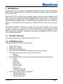
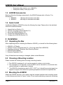
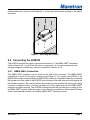
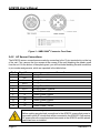
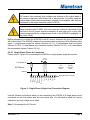
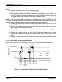
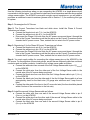
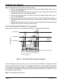
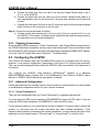
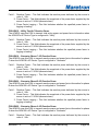
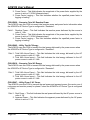
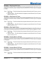
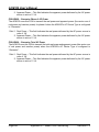
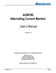
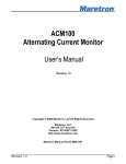
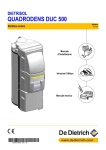
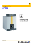
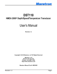
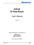
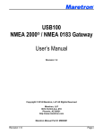
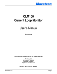
ACM100 Alternating Current Monitor User’s Manual Revision 1.3 Copyright © 2014 Maretron, LLP All Rights Reserved Maretron, LLP 9014 N. 23rd Ave #10 Phoenix, AZ 85021-7850 http://www.maretron.com Maretron Manual Part #: M001701 Revision 1.3 Page i ACM100 User’s Manual Revision History Revision Description 1.0 Original document 1.1 Corrected AC sensor part number Updated mounting drawing 1.2 Added sensed voltage and current range specifications Added prohibition of red Loctite threadlocking compound and cleaning agents containing acetone 1.3 Updated maximum voltage specifications Added description of connection to three-phase delta circuits Updated list of devices/programs that can be used for configuration Updated transmission intervals of transmitted messages Typographical corrections Expanded PGN entries in Appendix A Removed obsolete device priority subsection in configuration section Added mechanical drawings for current transducer accessories Page ii Revision 1.3 Table of Contents 1 Introduction ...........................................................................................................................1 1.1 Firmware Revision .................................................................................................... 1 1.2 ACM100 Features .................................................................................................... 1 1.3 ACM100 Accessories ............................................................................................... 2 1.4 Quick Install .............................................................................................................. 2 2 Installation .............................................................................................................................2 2.1 Unpacking the Box ................................................................................................... 2 2.2 Choosing a Mounting Location ................................................................................. 2 2.3 Mounting the ACM100 .............................................................................................. 2 2.4 Connecting the ACM100 .......................................................................................... 3 2.4.1 NMEA 2000® Connection............................................................................... 3 2.4.2 AC Sensor Connections ................................................................................ 4 2.4.2.1 Single-Phase (Phase A) Connection ................................................ 5 2.4.2.2 Single-Phase (Phase A, B) Connection ........................................... 6 2.4.2.3 Three-Phase Wye (Phase A, B, C) Connection ............................... 8 2.4.2.4 Three-Phase Delta (Phase A, B, C) Connection ............................ 10 2.4.3 Checking Connections ................................................................................. 12 2.5 Configuring the ACM100 ........................................................................................ 12 2.5.1 Advanced Configuration… ........................................................................... 12 2.5.1.1 Current Transducer A..................................................................... 12 2.5.1.2 Current Transducer B..................................................................... 13 2.5.1.3 Current Transducer C .................................................................... 13 2.5.1.4 Power Damping Period .................................................................. 13 2.5.1.5 V,I,F Damping Period ..................................................................... 13 2.5.1.6 Installation Description ................................................................... 13 2.5.1.7 NMEA 2000® PGN Enable/Disable ................................................ 13 2.5.1.8 Restore Factory Defaults ............................................................... 14 2.5.2 AC Circuit Type............................................................................................ 14 2.5.3 AC Device Type ........................................................................................... 14 2.5.4 Device Instance ........................................................................................... 14 2.5.5 Label ............................................................................................................ 14 2.5.6 Reset Total Energy Recorded...................................................................... 14 3 Output Parameters .............................................................................................................. 15 3.1 Line-Specific and Line-to-Neutral Measurements ................................................... 15 3.2 Line-to-Line Measurements .................................................................................... 15 4 Maintenance ........................................................................................................................ 16 5 Troubleshooting .................................................................................................................. 16 6 Technical Specifications ...................................................................................................... 17 7 Technical Support ............................................................................................................... 18 8 Installation Template ........................................................................................................... 19 9 Accessories Mechanical Drawings ...................................................................................... 20 10 Maretron (2 Year) Limited Warranty .................................................................................... 22 Revision 1.3 Page iii ACM100 User’s Manual Table of Figures Figure 1 – Mounting the ACM100 .............................................................................................. 3 Figure 2 – NMEA 2000® Connector Face Views ....................................................................... 4 Figure 3 – Single-Phase (Single Line) Connection Diagram...................................................... 5 Figure 4 – Single-Phase (Dual Line) Connection Diagram ........................................................ 6 Figure 5 – Three-Phase Wye Connection Diagram ................................................................... 8 Figure 6 – Three-Phase Delta Connection Diagram ................................................................ 10 Figure 7 – Mounting Surface Template ................................................................................... 19 Figure 8 – M000530 100A Current Transducer ....................................................................... 20 Figure 9 – M000612 400A Current Transducer ....................................................................... 21 Table of Appendices Appendix A – NMEA 2000® Interfacing.................................................................................... A1 Page iv Revision 1.3 1 Introduction Congratulations on your purchase of the Maretron Alternating Current (AC) Monitor (ACM100). Maretron has designed and built your ACM100 to the highest standards for years of dependable and accurate service. Maretron’s ACM100 is a device which monitors AC power sources and outputs information about these sources onto the industry standard NMEA 2000® marine data network. ACM100 output information is then displayed with networked NMEA 2000® equipment such as the Maretron DSM150/DSM250 dedicated display or with NMEA 2000® compatible software such as Maretron N2KView. The ACM100 can sense voltages up to 380VAC (line-to-neutral) and currents up to 400A. The Maretron ACM100 is designed to operate within the harsh demands of the marine environment. However, no piece of marine electronic equipment can function properly unless installed, configured, and maintained in the correct manner. Please read carefully and follow these instructions for installation, configuration, and usage of the Maretron ACM100 in order to ensure optimal performance. 1.1 Firmware Revision This manual corresponds to ACM100 firmware revision 1.0.9.2. 1.2 ACM100 Features The Maretron ACM100 has the following features. NMEA 2000® Interface Waterproof Connectors Sealed Waterproof Enclosure Opto-Isolated from NMEA 2000® Eliminating Potential Ground Loops Monitoring of busses carrying AC power and transmitting o Voltage o Frequency Monitoring AC Power Sources such as Utilities and Generators and transmitting: o Voltage o Current o Frequency o Real Power o Reactive Power o Apparent Power o Power Factor o Total Energy Imported o Total Energy Exported Can be used in the following configurations o 120VAC single phase o 120/240VAC split-phase o 230VAC single phase Revision 1.3 Page 1 ACM100 User’s Manual o Three-phase Wye (4-wire) up to (380/658Y) o Three-phase Delta (3-wire) up to 660V 1.3 ACM100 Accessories Maretron offers the following accessories for the ACM100 (please refer to Section ? for dimensions): M000630 100 Amp AC transducer with cable M000612 400 Amp AC transducer with cable 1.4 Quick Install Installing the Maretron ACM100 involves the following five steps. Please refer to the individual sections for additional details. 1. 2. 3. 4. 5. Unpack the box (Section 2.1) Choose a mounting location (Section 2.2) Mount the ACM100 (Section 2.3) Connect the ACM100 (Section 2.4) Configure the ACM100 (Section 2.5) 2 Installation 2.1 Unpacking the Box When unpacking the box containing the Maretron ACM100, you should find the following items: 1 – ACM100 – AC Monitor 1 – 100A AC Current Transducer with 5 ft. (1.5m) long cable (Part # M000630) 1 – Parts Bag containing 4 Stainless Steel Mounting Screws 1 – ACM100 User’s Manual 1 – Warranty Registration Card If any of these items are missing or damaged, please contact Maretron. 2.2 Choosing a Mounting Location Please consider the following when choosing a mounting location. 1. The ACM100 is waterproof, so it can be mounted in a damp or dry location. 2. The orientation is not important, so the ACM100 can be mounted on a horizontal deck, vertical bulkhead, or upside down if desired. 3. The ACM100 is temperature rated to 55°C (130°F), so it should be mounted away from engines or engine rooms where the operating temperature exceeds the specified limit. 2.3 Mounting the ACM100 Attach the ACM100 securely to the vessel using the included stainless steel mounting screws or other fasteners as shown in Figure 1 below. Do not use threadlocking compounds containing Page 2 Revision 1.3 methacrylate ester, such as Loctite Red (271), as they will cause stress cracking of the plastic enclosure. Figure 1 – Mounting the ACM100 2.4 Connecting the ACM100 The ACM100 requires two types of electrical connections: 1) the NMEA 2000® connection (refer to Section 2.4.1), and 2) the AC sensor connections (i.e., current transducer(s) and sensing voltage(s) connections), which are described in Section 2.4.2. 2.4.1 NMEA 2000® Connection The NMEA 2000® connector can be found on the side of the enclosure. The NMEA 2000® connector is a round five pin male connector (see Figure 2). You connect the ACM100 to an NMEA 2000® network using a Maretron NMEA 2000® cable (or compatible cable) by connecting the female end of the cable to the ACM100 (note the key on the male connector and keyway on the female connector). Be sure the cable is connected securely and that the collar on the cable connector is tightened firmly. Connect the other end of the cable (male) to the NMEA 2000® network in the same manner. The ACM100 is designed such that you can plug or unplug it from an NMEA 2000® network while the power to the network is connected or disconnected. Please follow recommended practices for installing NMEA 2000® network products. Revision 1.3 Page 3 ACM100 User’s Manual Figure 2 – NMEA 2000® Connector Face Views 2.4.2 AC Sensor Connections The ACM100 sensor connections are made by connecting to the 12-pin terminal strip on the top of the unit. First, remove the four screws at the corners of the unit detaching the splash guard from the unit. On the bottom of the splash guard, you will find a label detailing the wire connection to pin number assignments, which are repeated in the table below. Pin # 1 2 3 4 5 6 7 8 9 10 11 12 Signal Name VALine VBLine VCLine VANeutral VBNeutral VCNeutral IA+ IAIB+ IBIC+ IC- Connection Voltage Phase A Line Voltage Phase B Line Voltage Phase C Line Voltage Phase A Neutral Voltage Phase B Neutral Voltage Phase C Neutral Current Phase A Plus Current Phase A Minus Current Phase B Plus Current Phase B Minus Current Phase C Plus Current Phase C Minus WARNING: The voltages present on AC circuits can cause electrocution. Before making any electrical connections to the ACM100, ensure that power is removed from all AC circuits that will be connected to the ACM100. Only restore AC power after all connections have been made to the ACM100 and the splash guard has been re-installed. Page 4 Revision 1.3 WARNING: If the supplied current transducer is placed around a wire carrying AC current, then extremely high voltages can develop on the output leads of the current transducer, with severe risk of electrocution. For safety, keep the output leads of the current transducer(s) shorted or tied together until they are connected to the proper terminals on the ACM100. WARNING: User supplied voltage sense cables must be 18 gauge or larger, have insulation rated to 600V, and must have the conductor connected to the hot lead of the AC power source protected by a fuse rated at 3A or less (the current consumed by the voltage sense circuit on the ACM100 is negligible, at less than 10mA). Before attempting to connect the ACM100 to the AC source, determine the type of system you will be monitoring. The ACM100 supports the connection and monitoring of four different system types; 1) single-phase single line system (Section 2.4.2.1), 2) single-phase dual line system (Section 2.4.2.2), 3) three-phase wye connected system (Section 2.4.2.3), or 4) three-phase delta connected system (Section 2.4.2.4). 2.4.2.1 Single-Phase (Phase A) Connection Please refer to Figure 3 for connecting the ACM100 to a single phase, single line system. Current Transducer AC Source Fuse Line (Phase A) Neutral + + U.S. 120 Volts 60Hz Europe 220 Volts 50Hz - - ACM100 Screw Terminals 2 3 4 5 6 7 8 9 10 11 12 VALine VBLine VCLine VANeutral VBNeutral VCNeutral IA+ IAIB+ IBIC+ IC- 1 Figure 3 – Single-Phase (Single Line) Connection Diagram Use the following instructions when you are connecting the ACM100 to a single-phase circuit connected via one (hot) phase wire and one neutral wire. You will need to install one current transducer and one voltage sense cable. Step 1: De-energize the AC Source. Revision 1.3 Page 5 ACM100 User’s Manual Step 2: The Current Transducer has black and white wires. Install the Current Transducer as follows: a. Connect the black wire to pin 7 (IA+) on the ACM100 b. Connect the white wire to pin 8 (IA-) on the ACM100 c. Disconnect the hot wire from the AC power source and place it through the hole in the Current Transducer such that the arrow on the Current Transducer points towards the AC power source. Then, reattach the hot wire to the AC source. Step 3: You must supply a cable for connecting the voltage sense pins on the ACM100 to the AC source. For the purposes of these instructions, we will assume that the cable has one black conductor and one white conductor. Install the voltage sense cable as follows: a. Connect the white wire from one end of the Voltage Sense cable to pin 4 (VANeutral) on the ACM100. b. Connect the white wire from the other end of the Voltage Sense cable to the neutral wire of the AC source being monitored. c. Connect the black wire from one end of the Voltage Sense cable to pin 1 (VALine) on the ACM100 d. Connect the black wire from the other end of the Voltage Sense cable to a fuse appropriately sized for the black wire (18 gauge wire minimum and 3 amp fuse or less). e. Connect the other end of the fuse to the AC source hot wire (the fuse should be placed within 6 inches of the connection to the hot wire). 2.4.2.2 Single-Phase (Phase A, B) Connection Please refer to Figure 4 for connecting the ACM100 to a single phase, dual line system. Current Transducer Fuse Current Transducer Line (Phase A) Fuse AC Source Line (Phase B) Neutral + + U.S. 120 Volts 60Hz Europe 220 Volts 50Hz - - ACM100 Screw Terminals 2 3 4 5 6 7 8 9 10 11 12 VALine VBLine VCLine VANeutral VBNeutral VCNeutral IA+ IAIB+ IBIC+ IC- 1 Figure 4 – Single-Phase (Dual Line) Connection Diagram Page 6 Revision 1.3 Use the following instructions when you are connecting the ACM100 to a single-phase circuit connected via two hot wires. You will need to install two current transducer and two user-supplied voltage sense cables. The ACM100 comes with a single current transducer so you will need to purchase an additional current transducer (please refer to Section 1.3) for monitoring this type of system. Step 1: De-energize the AC Source. Step 2: The Current Transducer has black and white wires. Install the Phase A Current Transducer as follows: a. Connect the black wire to pin 7 (IA+) on the ACM100 b. Connect the white wire to pin 8 (IA-) on the ACM100 c. Disconnect the Phase A hot wire from the AC power source and place it through the hole in the Current Transducer such that the arrow on the Current Transducer points towards the AC power source. Then, reattach the hot wire to the AC power source. Step 3: Repeat step 2 for the Phase B Current Transducer as follows: a. Connect the black wire to pin 9 (IB+) on the ACM100 b. Connect the white wire to pin 10 (IB-) on the ACM100 c. Disconnect the Phase B hot wire from the AC power source and place it through the hole in the Current Transducer such that the arrow on the Current Transducer points towards the AC power source. Then, reattach the hot wire to the AC power source. Step 4: You must supply cables for connecting the voltage sense pins on the ACM100 to the AC source. For the purposes of these instructions, we will assume that each cable has one black conductor and one white conductor. Install the first voltage sense cable as follows: a. Connect the white wire from one end of the first Voltage Sense cable to pin 4 (VANeutral) on the ACM100. b. Connect the white wire from the other end of the first Voltage Sense cable to the neutral wire of the AC source being monitored c. Connect the black wire from one end of the first Voltage Sense cable to pin 1 (VALine) on the ACM100 d. Connect the black wire from the other end of the first Voltage Sense cable to a fuse appropriately sized for the black wire (18 gauge wire minimum and 3 amp fuse or less). e. Connect the other end of the fuse to the AC source hot wire (the fuse should be placed within 6 inches of the connection to the hot wire). Step 5: Install the second Voltage Sense cable as follows: a. Connect the white wire from one end of the second Voltage Sense cable to pin 5 (VBNeutral) on the ACM100. b. Connect the white wire from the other end of the second Voltage Sense cable to the neutral wire of the AC source being monitored. c. Connect the black wire from one end of the second Voltage Sense cable to pin 2 (VBLine) on the ACM100 Revision 1.3 Page 7 ACM100 User’s Manual d. Connect the black wire from the other end of the second Voltage Sense cable to a fuse appropriately sized for the black wire (18 gauge wire minimum and 3 amp fuse or less). e. Connect the other end of the fuse to the AC source hot wire (the fuse should be placed within 6 inches of the connection to the hot wire). 2.4.2.3 Three-Phase Wye (Phase A, B, C) Connection Please refer to Figure 5 for connecting the ACM100 to a three phase wye system. Current Transducer Fuse Line (Phase C) Current Transducer Fuse Current Transducer Line (Phase A) Fuse AC Source Line (Phase B) Neutral + + U.S. 120 Volts 60Hz Europe 220 Volts 50Hz - - ACM100 Screw Terminals 2 3 4 5 6 7 8 9 10 11 12 VALine VBLine VCLine VANeutral VBNeutral VCNeutral IA+ IAIB+ IBIC+ IC- 1 Figure 5 – Three-Phase Wye Connection Diagram Use the following instructions when you are connecting the ACM100 to a three-phase “Wye” circuit connected via three hot wires and a single neutral. You will need to install three current transducers and three user-supplied voltage sense cables. The ACM100 comes with a single current transducer so you will need to purchase two additional current transducers for monitoring this type of system. Step 1: De-energize the AC Source. Step 2: The Current Transducer has black and white wires. Install the first Current Transducer as follows: a. Connect the black wire to pin 7 (IA+) on the ACM100 b. Connect the white wire to pin 8 (IA-) on the ACM100 c. Disconnect the Phase A hot wire from the AC power source and place it through the hole in the Current Transducer such that the arrow on the Current Transducer points Page 8 Revision 1.3 towards the AC power source. Then, reattach the Phase A hot wire to the AC power source. Step 3: Install the second Current Transducer as follows: a. Connect the black wire to pin 9 (IB+) on the ACM100 b. Connect the white wire to pin 10 (IB-) on the ACM100 c. Disconnect the Phase B hot wire from the AC power source and place it through the hole in the Current Transducer such that the arrow on the Current Transducer points towards the AC power source. Then, reattach the Phase B hot wire to the AC power source. Step 4: Install the third Current Transducer as follows: a. Connect the black wire to pin 11 (IC+) on the ACM100 b. Connect the white wire to pin 12 (IC-) on the ACM100 c. Disconnect the Phase C hot wire from the AC power source and place it through the hole in the Current Transducer such that the arrow on the Current Transducer points towards the AC power source. Then, reattach the Phase C hot wire to the AC power source. Step 5: You must supply a cable for connecting the voltage sense pins on the ACM100 to the AC source. For the purposes of these instructions, we will assume that the cable has one black conductor and one white conductor. Install the voltage sense cable as follows: a. Connect the white wire from one end of the Voltage Sense cable to pin 4 (VANeutral) on the ACM100. b. Connect the white wire from the other end of the Voltage Sense cable to the neutral wire of the AC source being monitored. c. Connect the black wire from one end of the Voltage Sense cable to pin 1 (VALine) on the ACM100 d. Connect the black wire from the other end of the Voltage Sense cable to a fuse appropriately sized for the black wire (18 gauge wire minimum and 3 amp fuse or less). e. Connect the other end of the fuse to the AC source hot wire (the fuse should be placed within 6 inches of the connection to the hot wire). Step 6: Install the second Voltage Sense cable as follows: a. Connect the white wire from one end of the second Voltage Sense cable to pin 5 (VBNeutral) on the ACM100. b. Connect the white wire from the other end of the second Voltage Sense cable to the neutral wire of the AC source being monitored. c. Connect the black wire from one end of the second Voltage Sense cable to pin 2 (VBLine) on the ACM100 d. Connect the black wire from the other end of the second Voltage Sense cable to a fuse appropriately sized for the black wire (18 gauge wire minimum and 3 amp fuse or less). e. Connect the other end of the fuse to the AC source hot wire (the fuse should be placed within 6 inches of the connection to the hot wire). Revision 1.3 Page 9 ACM100 User’s Manual Step 7: Install the third Voltage Sense cable as follows: a. Connect the white wire from one end of the second Voltage Sense cable to pin 6 (VCNeutral) on the ACM100. b. Connect the white wire from the other end of the second Voltage Sense cable to the neutral wire of the AC source being monitored. c. Connect the black wire from one end of the second Voltage Sense cable to pin 3 (VCLine) on the ACM100 d. Connect the black wire from the other end of the second Voltage Sense cable to a fuse appropriately sized for the black wire (18 gauge wire minimum and 3 amp fuse or less). e. Connect the other end of the fuse to the AC source hot wire (the fuse should be placed within 6 inches of the connection to the hot wire). 2.4.2.4 Three-Phase Delta (Phase A, B, C) Connection Please refer to Figure 6 for connecting the ACM100 to a three phase delta system. Current Transducer Fuse Line (Phase C) Current Transducer + Fuse Max 380 Volts 50-60Hz Current Transducer Line (Phase A) Fuse AC Source Line (Phase B) “Floating” Neutral ACM100 Screw Terminals 2 3 4 5 6 7 8 9 10 11 12 VALine VBLine VCLine VANeutral VBNeutral VCNeutral IA+ IAIB+ IBIC+ IC- 1 Figure 6 – Three-Phase Delta Connection Diagram Use the following instructions when you are connecting the ACM100 to a three-phase delta circuit connected via three hot wires. You will need to install three current transducers and three user-supplied voltage sense cables. The ACM100 comes with a single current transducer so you will need to purchase two optional current transducers (please refer to Section 1.3) for monitoring this type of system. Step 1: De-energize the AC Source. Page 10 Revision 1.3 Step 2: The Current Transducer has black and white wires. Install the first Current Transducer as follows: a. Connect the black wire to pin 7 (IA+) on the ACM100 b. Connect the white wire to pin 8 (IA-) on the ACM100 c. Disconnect the Phase A hot wire from the AC power source and place it through the hole in the Current Transducer such that the arrow on the Current Transducer points towards the AC power source. Then, reattach the Phase A hot wire to the AC power source. Step 3: Install the second Current Transducer as follows: a. Connect the black wire to pin 9 (IB+) on the ACM100 b. Connect the white wire to pin 10 (IB-) on the ACM100 c. Disconnect the Phase B hot wire from the AC power source and place it through the hole in the Current Transducer such that the arrow on the Current Transducer points towards the AC power source. Then, reattach the Phase B hot wire to the AC power source. Step 4: Install the third Current Transducer as follows: a. Connect the black wire to pin 11 (IC+) on the ACM100 b. Connect the white wire to pin 12 (IC-) on the ACM100 c. Disconnect the Phase C hot wire from the AC power source and place it through the hole in the Current Transducer such that the arrow on the Current Transducer points towards the AC power source. Then, reattach the Phase C hot wire to the AC power source. Step 5: You must supply a cable for connecting the voltage sense pins on the ACM100 to the AC source. For the purposes of these instructions, we will assume that the cable has one black conductor and one white conductor. Install the voltage sense cable as follows: a. Connect the black wire from one end of the Voltage Sense cable to pin 1 (VALine) on the ACM100 b. Connect the black wire from the other end of the Voltage Sense cable to a fuse appropriately sized for the black wire (18 gauge wire minimum and 3 amp fuse or less). c. Connect the other end of the fuse to the AC source hot wire (the fuse should be placed within 6 inches of the connection to the hot wire). Step 6: Install the second Voltage Sense cable as follows: a. Connect the black wire from one end of the second Voltage Sense cable to pin 2 (VBLine) on the ACM100 b. Connect the black wire from the other end of the second Voltage Sense cable to a fuse appropriately sized for the black wire (18 gauge wire minimum and 3 amp fuse or less). c. Connect the other end of the fuse to the AC source hot wire (the fuse should be placed within 6 inches of the connection to the hot wire). Step 7: Install the third Voltage Sense cable as follows: Revision 1.3 Page 11 ACM100 User’s Manual a. Connect the black wire from one end of the second Voltage Sense cable to pin 3 (VCLine) on the ACM100 b. Connect the black wire from the other end of the second Voltage Sense cable to a fuse appropriately sized for the black wire (18 gauge wire minimum and 3 amp fuse or less). c. Connect the other end of the fuse to the AC source hot wire (the fuse should be placed within 6 inches of the connection to the hot wire). Step 8: Connect the neutral terminals as follows: a. Connect a white wire between pin 4 (VANeutral), pin 5 (VBNeutral), and pin 6 (VCNeutral) on the ACM100. This creates a “floating neutral” signal that will enable measurements to be made without a true neutral connection. 2.4.3 Checking Connections Once the NMEA 2000® connection, Current Transducer(s), and Voltage Sense connection(s) to the ACM100 have been completed, restore power to the monitored AC source and check to see that information is being properly transmitted by observing an appropriate NMEA 2000® display. If you don’t see AC power data, refer to Section 5, “Troubleshooting”. 2.5 Configuring the ACM100 The ACM100 will transmit data over the NMEA 2000 network as it is shipped from the factory; however, it may require configuration, depending on the type of AC source being monitored. There are several configurable items within the ACM100, which are detailed in the remainder of this section. You configure the ACM100 using Maretron N2KAnalyzer® software or a Maretron DSM150/DSM250 display. Please refer to the N2KAnalyzer User’s Manual, DSM150 User’s Manual, or DSM250 User’s Manual, as appropriate, for details. 2.5.1 Advanced Configuration… Certain parameters do not normally need to be set in order for normal operation, but are included in an advanced configuration section for use in special situations. 2.5.1.1 Current Transducer A There are two configurable items for Current Transducer A: amperage and direction. If you are using the 100A current transducer (P/N #M000630), select the 100A option. If you are using the 400A current transducer (P/N #M000612), select the 400A option. For the direction setting, if you notice that the current of phase A is negative when it should be positive, or vice-versa, then the current transducer has been installed backwards. If this happens, then instead of reconnecting the current transducer, you may change the value of this parameter from the default value of “Normal Install” to “Inverse Install” to correct for this. Page 12 Revision 1.3 2.5.1.2 Current Transducer B There are two configurable items for Current Transducer B: amperage and direction. If you are using the 100A current transducer (P/N #M000630), select the 100A option. If you are using the 400A current transducer (P/N #M000612), select the 400A option. For the direction setting, if you notice that the current of phase B is negative when it should be positive, or vice-versa, then the current transducer has been installed backwards. If this happens, then instead of reconnecting the current transducer, you may change the value of this parameter from the default value of “Normal Install” to “Inverse Install” to correct for this. 2.5.1.3 Current Transducer C There are two configurable items for Current Transducer A: amperage and direction. If you are using the 100A current transducer (P/N #M000630), select the 100A option. If you are using the 400A current transducer (P/N #M000612), select the 400A option. For the direction setting, if you notice that the current of phase C is negative when it should be positive, or vice-versa, then the current transducer has been installed backwards. If this happens, then instead of reconnecting the current transducer, you may change the value of this parameter from the default value of “Normal Install” to “Inverse Install” to correct for this. 2.5.1.4 Power Damping Period If you feel that the monitored Power parameters are changing too quickly or too slowly on the display, you can adjust the damping that is applied to the output readings by adjusting this parameter. . The default damping period is 5 seconds. . You may change it to a value in the range of 0.2 seconds to 10 seconds. 2.5.1.5 V,I,F Damping Period If you feel that the monitored Voltage, Current, and Frequency parameters are changing too quickly or too slowly on the display, you can adjust the damping that is applied to the output readings by adjusting this parameter. . The default damping period is 0.5 seconds. . You may change it to a value in the range of 0.2 seconds to 10 seconds. 2.5.1.6 Installation Description You can configure the two installation description parameters with any text you wish. Examples include date of installation, location, etc. NMEA 2000 diagnostic tools such as Maretron N2KAnalyzer® can display this information. 2.5.1.7 NMEA 2000® PGN Enable/Disable The ACM100 is capable of transmitting many different kinds of NMEA 2000® messages (or PGNs) associated with AC power sources. You may individually enable or disable each of these messages. You may also change the rate of transmission of each of these messages if desired. Revision 1.3 Page 13 ACM100 User’s Manual 2.5.1.8 Restore Factory Defaults Selecting this configuration option causes all stored parameters in the ACM100 to be reset to the values they contained when the unit was manufactured. 2.5.2 AC Circuit Type You must configure the ACM100 as to what type of AC circuit connection it is monitoring. The allowable values for this parameter are as follows: Single-Phase (Phase A) – use this value when power is connected via a single hot wire and a single neutral wire (a typical 110VAC connection in the US). Single-Phase (Phase A, B) – use this value when power is connected via the two hot wires and single neutral wire from a single phase of a transducer (a typical 220VAC connection in the US). Three-Phase (Phase A, B, C) – use this value when power is connected via the three hot wires and single neutral wire from a three-phase “Wye” or “Delta” connected circuit. 2.5.3 AC Device Type You must configure the ACM100 as to what type of AC source it is monitoring. The allowable values for this parameter are as follows: “Generator” (default) – use this value when you are monitoring the output of a genset. “Utility” – use this value when you are monitoring shore power “Bus” – use this value if you are monitoring power flowing across a cable that is not located directly at the output of a genset or a shore power connection (e.g., an AC selection switch might have as an input the shore power and another input from the genset, connecting the ACM100 at the output of the AC selection switch would require the ACM100 to be configured as “Bus”. 2.5.4 Device Instance NMEA 2000® provides a unique AC power instance for each AC power source on a vessel. This value should be programmed in each ACM100 so that each ACM100 is associated with a unique device instance number. The default instance number is 0, which is used to indicate the first ACM100 that is hooked to the network. Subsequent ACM100s connected to the network would be numbered 1, 2, and so on. 2.5.5 Label Program this parameter with a text string which identifies this device. Maretron display products will display this label text when you are selecting data to display. 2.5.6 Reset Total Energy Recorded The ACM100 accumulates the total energy imported from a Utility and exported from a generator. Select this option to zero the total energy accumulated readings in the ACM100. Page 14 Revision 1.3 3 Output Parameters The ACM100 outputs a variety of information about the AC power source onto the NMEA 2000 network. The tables below detail which measurements are made available on the bus for the different combinations of different AC source types and circuit types which may be selected. 3.1 Line-Specific and Line-to-Neutral Measurements AC Source Type Available Data Parameter Bus Generator Utility Average Phase A Phase B Phase C Line-Neutral AC 1 RMS Voltage AC RMS Current 1 AC Frequency 1 Real Power 1 Apparent Power 1 Reactive Power 1 Power Factor 1 Total kW Hours Export Total kW Hours Import Notes: 1. Available only if circuit type has been set to “Single-Phase (Phase A,B)” or “Three-Phase (Phase A,B,C)” 2. Available only if circuit type has been set to “Three-Phase (Phase A,B,C)” 2 2 2 2 2 2 2 3.2 Line-to-Line Measurements AC Source Type Available Data Parameter Bus Generator Utility Average Phase A Phase B Phase C to to to Phase B Phase C Phase A Line-Line AC RMS 1 2 Voltage Notes: 1. Available only if circuit type has been set to “Single-Phase (Phase A,B)” or “Three-Phase (Phase A,B,C)” 2. Available only if circuit type has been set to “Three-Phase (Phase A,B,C)” Revision 1.3 2 Page 15 ACM100 User’s Manual 4 Maintenance Regular maintenance is important to ensure continued proper operation of the Maretron ACM100. Perform the following tasks periodically: Clean the unit with a soft cloth. Do not use chemical cleaners as they may remove paint or markings or may corrode the ACM100 enclosure or seals. Do not use any cleaners containing acetone, as they will deteriorate the plastic enclosure. Ensure that the unit is mounted securely and cannot be moved relative to the mounting surface. If the unit is loose, tighten the mounting screws. Check the security of the cable connected to the NMEA 2000® connector, and tighten if necessary. Check the security of all of the current transducer connections and voltage transducer connections on the top of the unit and tighten if necessary. 5 Troubleshooting If you notice unexpected operation of the Maretron ACM100, follow the troubleshooting procedures in this section to remedy simple problems. If these steps do not solve your problem, please contact Maretron Technical Support (refer to Section 7 for contact information). Symptom No AC power data visible on NMEA 2000® network. Troubleshooting Procedure Ensure that the ACM100 is properly connected to the NMEA 2000® network. Ensure that the current transducers and voltage sense cables are properly connected to the ACM100. Ensure that the ACM100 has the appropriate NMEA 2000® PGNs enabled as described in Section 1. Exported power is increasing when it shouldn’t be The current transducer(s) are installed backwards. Either 1) reinstall the current transducers in the opposite direction of 2) configure the ACM100 to recognize the reversed installation as described in Sections 1, 1, and 1. Imported power in not increasing when it should be Currents are showing as negative values when they should be showing as positive values Power readings are not what I expect Page 16 Please review carefully the installation instructions in Section 2.4.2 and the configuration of the circuit type in Section 0. Revision 1.3 6 Technical Specifications As Maretron is constantly improving its products, all specifications are subject to change without notice. Maretron products are designed to be accurate and reliable; however, they should be used only as aids to navigation and not as a replacement for traditional navigation aids and techniques. Certifications Parameter NMEA 2000® Maritime Navigation and Radiocommunication Equipment & Systems FCC and CE Mark Comment Level A IEC 60945 Electromagnetic Compatibility NMEA 2000® Parameter Group Numbers (PGNs) Description Periodic Data PGNs Response to Requested PGNs Protocol PGNs Maretron Proprietary PGNs Revision 1.3 PGN # 65001 65002 65003 65004 65005 65006 65007 65008 65009 65010 65011 65012 65013 65014 65015 65016 65017 65018 65019 65020 65021 65022 65023 65024 65025 65026 65027 65028 65029 65030 126464 126996 126998 059392 059904 060928 065240 126208 126720 PGN Name Bus #1 Phase C Basic AC Quantities Bus #1 Phase B Basic AC Quantities Bus #1 Phase A Basic AC Quantities Bus #1 Average Basic AC Quantities Utility Total AC Energy Utility Phase C AC Reactive Power Utility Phase C AC Power Utility Phase C AC Basic Quantities Utility Phase B AC Reactive Power Utility Phase B AC Power Utility Phase B AC Basic Quantities Utility Phase A AC Reactive Power Utility Phase A AC Power Utility Phase A AC Basic Quantities Utility Total AC Reactive Power Utility Total AC Power Utility Average Basic AC Quantities Generator Total AC Energy Generator Phase C AC Reactive Power Generator Phase C AC Power Generator Phase C AC Basic Quantities Generator Phase B AC Reactive Power Generator Phase B AC Power Generator Phase B AC Basic Quantities Generator Phase A AC Reactive Power Generator Phase A AC Power Generator Phase A AC Basic Quantities Generator Total AC Reactive Power Generator Total AC Power Generator Average Basic AC Quantities PGN List (Transmit and Receive) Product Information Configuration Information ISO Acknowledge ISO Request ISO Address Claim ISO Address Command NMEA Configuration Default Rate Disabled Disabled Disabled 2 times/second 2 times/second Disabled Disabled Disabled Disabled Disabled Disabled Disabled Disabled Disabled 2 times/second 2 times/second 2 times/second 2 times/second Disabled Disabled Disabled Disabled Disabled Disabled Disabled Disabled Disabled 2 times/second 2 times/second 2 times/second N/A N/A N/A N/A N/A N/A N/A N/A N/A Page 17 ACM100 User’s Manual Electrical Parameter Measurement Voltage Range Measurement Voltage Accuracy Measurement Current Range Value 0-380 VAC ±1% 0-100 A Measurement Current Accuracy Operating Voltage Power Consumption Load Equivalence Number (LEN) Reverse Battery Protection Load Dump Protection ±1% 9 to 32 Volts 100 mA 2 Yes Yes Comment 120,120/240,240,208Y,380Y configurations With included current transducer (0 to 400A with optional transducer) With included current transducer DC Voltage NMEA 2000® Interface NMEA 2000® Spec. (1LEN = 50 mA) Indefinitely Energy Rated per SAE J1113 Mechanical Parameter Value Comment 3.50” x 4.20” x 2.03” Including Flanges for Mounting (88.9mm x 106.7mm x 51.6mm) 13 oz. (368.5 g) Size Weight Environmental Parameter IEC 60945 Classification Degree of Protection Operating Temperature Storage Temperature Relative Humidity Vibration Solar Radiation Corrosion (Salt Mist) Electromagnetic Emission Electromagnetic Immunity Safety Precautions Value Exposed IP64 -25°C to 55°C -40°C to 70°C 93%RH @40° per IEC60945-8.2 2-13.2Hz @ ±1mm, 13.2-100Hz @ 7m/s2 per IEC 60945-8.7 Ultraviolet B, A, Visible, and Infrared per IEC 60945-8.10 4 times 7days @ 40°C, 95%RH after 2 hour Salt Spray Per IEC 60945-8.12 Conducted and Radiated Emission per IEC 60945-9 Conducted, Radiated, Supply, and ESD per IEC 60945-10 Dangerous Voltage, Electromagnetic Radio Frequency per IEC 60945-12 7 Technical Support If you require technical support for Maretron products, you can reach us in any of the following ways: Telephone: Fax: E-mail: World Wide Web: Mail: Page 18 1-866-550-9100 1-602-861-1777 [email protected] http://www.maretron.com Maretron, LLC Attn: Technical Support 9014 N. 23rd Ave Suite 10 Phoenix, AZ 85021 USA Revision 1.3 8 Installation Template Please check the dimensions before using the following diagram as a template for drilling the mounting holes because the printing process may have distorted the dimensions. Figure 7 – Mounting Surface Template Revision 1.3 Page 19 ACM100 User’s Manual 9 Accessories Mechanical Drawings Figure 8 – M000530 100A Current Transducer Page 20 Revision 1.3 Figure 9 – M000612 400A Current Transducer Revision 1.3 Page 21 ACM100 User’s Manual 10 Maretron (2 Year) Limited Warranty Maretron warrants the ACM100 to be free from defects in materials and workmanship for two (2) years from the date of original purchase. If within the applicable period any such products shall be proved to Maretron’s satisfaction to fail to meet the above limited warranty, such products shall be repaired or replaced at Maretron’s option. Purchaser's exclusive remedy and Maretron’s sole obligation hereunder, provided product is returned pursuant to the return requirements below, shall be limited to the repair or replacement, at Maretron’s option, of any product not meeting the above limited warranty and which is returned to Maretron; or if Maretron is unable to deliver a replacement that is free from defects in materials or workmanship, Purchaser’s payment for such product will be refunded. Maretron assumes no liability whatsoever for expenses of removing any defective product or part or for installing the repaired product or part or a replacement therefore or for any loss or damage to equipment in connection with which Maretron’s products or parts shall be used. With respect to products not manufactured by Maretron, Maretron’s warranty obligation shall in all respects conform to and be limited to the warranty actually extended to Maretron by its supplier. The foregoing warranties shall not apply with respect to products subjected to negligence, misuse, misapplication, accident, damages by circumstances beyond Maretron’s control, to improper installation, operation, maintenance, or storage, or to other than normal use or service. THE FOREGOING WARRANTIES ARE EXPRESSLY IN LIEU OF AND EXCLUDES ALL OTHER EXPRESS OR IMPLIED WARRANTIES, INCLUDING BUT NOT LIMITED TO THE IMPLIED WARRANTIES OF MERCHANTABILITY AND OF FITNESS FOR A PARTICULAR PURPOSE. Statements made by any person, including representatives of Maretron, which are inconsistent or in conflict with the terms of this Limited Warranty, shall not be binding upon Maretron unless reduced to writing and approved by an officer of Maretron. IN NO CASE WILL MARETRON BE LIABLE FOR INCIDENTAL OR CONSEQUENTIAL DAMAGES, DAMAGES FOR LOSS OF USE, LOSS OF ANTICIPATED PROFITS OR SAVINGS, OR ANY OTHER LOSS INCURRED BECAUSE OF INTERRUPTION OF SERVICE. IN NO EVENT SHALL MARETRON’S AGGREGATE LIABILITY EXCEED THE PURCHASE PRICE OF THE PRODUCT(S) INVOLVED. MARETRON SHALL NOT BE SUBJECT TO ANY OTHER OBLIGATIONS OR LIABILITIES, WHETHER ARISING OUT OF BREACH OF CONTRACT OR WARRANTY, TORT (INCLUDING NEGLIGENCE), OR OTHER THEORIES OF LAW WITH RESPECT TO PRODUCTS SOLD OR SERVICES RENDERED BY MARETRON, OR ANY UNDERTAKINGS, ACTS OR OMISSIONS RELATING THERETO. Maretron does not warrant that the functions contained in any software programs or products will meet purchaser’s requirements or that the operation of the software programs or products will be uninterrupted or error free. Purchaser assumes responsibility for the selection of the software programs or products to achieve the intended results, and for the installation, use and results obtained from said programs or products. No specifications, samples, descriptions, or illustrations provided Maretron to Purchaser, whether directly, in trade literature, brochures or other documentation shall be construed as warranties of any kind, and any failure to conform with such specifications, samples, descriptions, or illustrations shall not constitute any breach of Maretron’s limited warranty. Warranty Return Procedure: To apply for warranty claims, contact Maretron or one of its dealers to describe the problem and determine the appropriate course of action. If a return is necessary, place the product in its original packaging together with proof of purchase and send to an Authorized Maretron Service Location. You are responsible for all shipping and insurance charges. Maretron will return the replaced or repaired product with all shipping and handling prepaid except for requests requiring expedited shipping (i.e. overnight shipments). Failure to follow this warranty return procedure could result in the product’s warranty becoming null and void. Maretron reserves the right to modify or replace, at its sole discretion, without prior notification, the warranty listed above. To obtain a copy of the then current warranty policy, please go to the following web page: http://www.maretron.com/company/warranty.php Page 22 Revision 1.3 Appendix A – NMEA 2000® Interfacing ACM100 NMEA 2000® Periodic Data Transmitted PGNs PGN 65001 – Bus #1 Phase C Basic AC Quantities The ACM100 uses this PGN to transmit voltage, frequency, and current information for phase C when the ACM100’s AC Device Type is configured to “Bus”. Field 1: Line-Line AC RMS Voltage – This field indicates the AC RMS voltage between this phase and the next phase in units of 1 V. 2: Line-Neutral AC RMS Voltage – This field indicates the AC RMS voltage between this phase and the neutral phase in units of 1 V. 3: AC Frequency – This field indicates the frequency of the AC voltage in units of 1/128 Hz. 4: AC RMS Current (not transmitted for the “Bus” AC Source Type) – This field indicates the current flowing through the specified phase in units of 1 A. PGN 65002 – Bus #1 Phase B Basic AC Quantities The ACM100 uses this PGN to transmit voltage, frequency, and current information for phase B when the ACM100’s AC Device Type is configured to “Bus”. Field 1: Line-Line AC RMS Voltage – This field indicates the AC RMS voltage between this phase and the next phase in units of 1 V. 2: Line-Neutral AC RMS Voltage – This field indicates the AC RMS voltage between this phase and the neutral phase in units of 1 V. 3: AC Frequency – This field indicates the frequency of the AC voltage in units of 1/128 Hz. 4: AC RMS Current (not transmitted for the “Bus” AC Source Type) – This field indicates the current flowing through the specified phase in units of 1 A. PGN 65003 – Bus #1 Phase A Basic AC Quantities The ACM100 uses this PGN to transmit voltage, frequency, and current information for phase A when the ACM100’s AC Device Type is configured to “Bus”. Field 1: Line-Line AC RMS Voltage – This field indicates the AC RMS voltage between this phase and the next phase in units of 1 V. 2: Line-Neutral AC RMS Voltage – This field indicates the AC RMS voltage between this phase and the neutral phase in units of 1 V. 3: AC Frequency – This field indicates the frequency of the AC voltage in units of 1/128 Hz. 4: AC RMS Current (not transmitted for the “Bus” AC Source Type) – This field indicates the current flowing through the specified phase in units of 1 A. PGN 65004 – Bus #1 Average Basic AC Quantities The ACM100 uses this PGN to transmit average voltage, frequency, and current information when the ACM100’s AC Device Type is configured to “Bus”. Revision 1.3 Appendix A – NMEA 2000 Interfacing Page A1 ACM100 User’s Manual Field 1: Line-Line AC RMS Voltage – This field indicates the AC RMS voltage between this phase and the next phase in units of 1 V. 2: Line-Neutral AC RMS Voltage – This field indicates the AC RMS voltage between this phase and the neutral phase in units of 1 V. 3: AC Frequency – This field indicates the frequency of the AC voltage in units of 1/128 Hz. 4: AC RMS Current (not transmitted for the “Bus” AC Source Type) – This field indicates the current flowing through the specified phase in units of 1 A. PGN 65008 – Utility Phase C Basic AC Quantities The ACM100 uses this PGN to transmit voltage, frequency, and current information for phase C when the ACM100’s AC Device Type is configured to “Utility”. Field 1: Line-Line AC RMS Voltage – This field indicates the AC RMS voltage between this phase and the next phase in units of 1 V. 2: Line-Neutral AC RMS Voltage – This field indicates the AC RMS voltage between this phase and the neutral phase in units of 1 V. 3: AC Frequency – This field indicates the frequency of the AC voltage in units of 1/128 Hz. 4: AC RMS Current (not transmitted for the “Bus” AC Source Type) – This field indicates the current flowing through the specified phase in units of 1 A. PGN 65011 – Utility Phase B Basic AC Quantities The ACM100 uses this PGN to transmit voltage, frequency, and current information for phase B when the ACM100’s AC Device Type is configured to “Utility”. Field 1: Line-Line AC RMS Voltage – This field indicates the AC RMS voltage between this phase and the next phase in units of 1 V. 2: Line-Neutral AC RMS Voltage – This field indicates the AC RMS voltage between this phase and the neutral phase in units of 1 V. 3: AC Frequency – This field indicates the frequency of the AC voltage in units of 1/128 Hz. 4: AC RMS Current (not transmitted for the “Bus” AC Source Type) – This field indicates the current flowing through the specified phase in units of 1 A. PGN 65014 – Utility Phase A Basic AC Quantities The ACM100 uses this PGN to transmit voltage, frequency, and current information for phase A when the ACM100’s AC Device Type is configured to “Utility”. Field 1: Line-Line AC RMS Voltage – This field indicates the AC RMS voltage between this phase and the next phase in units of 1 V. 2: Line-Neutral AC RMS Voltage – This field indicates the AC RMS voltage between this phase and the neutral phase in units of 1 V. 3: AC Frequency – This field indicates the frequency of the AC voltage in units of 1/128 Hz. Page A2 Appendix A – NMEA 2000 Interfacing Revision 1.3 4: AC RMS Current (not transmitted for the “Bus” AC Source Type) – This field indicates the current flowing through the specified phase in units of 1 A. PGN 65017 – Utility Average Basic AC Quantities The ACM100 uses this PGN to transmit average voltage, frequency, and current information when the ACM100’s AC Device Type is configured to “Utility”. Field 1: Line-Line AC RMS Voltage – This field indicates the AC RMS voltage between this phase and the next phase in units of 1 V. 2: Line-Neutral AC RMS Voltage – This field indicates the AC RMS voltage between this phase and the neutral phase in units of 1 V. 3: AC Frequency – This field indicates the frequency of the AC voltage in units of 1/128 Hz. 4: AC RMS Current (not transmitted for the “Bus” AC Source Type) – This field indicates the current flowing through the specified phase in units of 1 A. PGN 65021 – Generator Phase C Basic AC Quantities The ACM100 uses this PGN to transmit voltage, frequency, and current information for phase C when the ACM100’s AC Device Type is configured to “Generator”. . Field 1: Line-Line AC RMS Voltage – This field indicates the AC RMS voltage between this phase and the next phase in units of 1 V. 2: Line-Neutral AC RMS Voltage – This field indicates the AC RMS voltage between this phase and the neutral phase in units of 1 V. 3: AC Frequency – This field indicates the frequency of the AC voltage in units of 1/128 Hz. 4: AC RMS Current (not transmitted for the “Bus” AC Source Type) – This field indicates the current flowing through the specified phase in units of 1 A. PGN 65024 – Generator Phase B Basic AC Quantities The ACM100 uses this PGN to transmit voltage, frequency, and current information for phase B when the ACM100’s AC Device Type is configured to “Generator”. Field 1: Line-Line AC RMS Voltage – This field indicates the AC RMS voltage between this phase and the next phase in units of 1 V. 2: Line-Neutral AC RMS Voltage – This field indicates the AC RMS voltage between this phase and the neutral phase in units of 1 V. 3: AC Frequency – This field indicates the frequency of the AC voltage in units of 1/128 Hz. 4: AC RMS Current (not transmitted for the “Bus” AC Source Type) – This field indicates the current flowing through the specified phase in units of 1 A. PGN 65027 – Generator Phase A Basic AC Quantities The ACM100 uses this PGN to transmit voltage, frequency, and current information ofor phase A when the ACM100’s AC Device Type is configured to “Generator”. Revision 1.3 Appendix A – NMEA 2000 Interfacing Page A3 ACM100 User’s Manual Field 1: Line-Line AC RMS Voltage – This field indicates the AC RMS voltage between this phase and the next phase in units of 1 V. 2: Line-Neutral AC RMS Voltage – This field indicates the AC RMS voltage between this phase and the neutral phase in units of 1 V. 3: AC Frequency – This field indicates the frequency of the AC voltage in units of 1/128 Hz. 4: AC RMS Current (not transmitted for the “Bus” AC Source Type) – This field indicates the current flowing through the specified phase in units of 1 A. PGN 65030 – Generator Average Basic AC Quantities The ACM100 uses this PGN to transmit average voltage, frequency, and current information when the ACM100’s AC Device Type is configured to “Generator”. Field 1: Line-Line AC RMS Voltage – This field indicates the AC RMS voltage between this phase and the next phase in units of 1 V. 2: Line-Neutral AC RMS Voltage – This field indicates the AC RMS voltage between this phase and the neutral phase in units of 1 V. 3: AC Frequency – This field indicates the frequency of the AC voltage in units of 1/128 Hz. 4: AC RMS Current (not transmitted for the “Bus” AC Source Type) – This field indicates the current flowing through the specified phase in units of 1 A. PGN 65006 – Utility Phase C AC Reactive Power The ACM100 uses this PGN to transmit reactive power and power factor information for phase C when the ACM100’s AC Device Type is configured to “Utility”. Field 1: Reactive Power – This field indicates the reactive power delivered by the source in units of 1 VAr. 2: Power Factor – This field indicates the magnitude of the power factor supplied by the source in units of 1/16384 (dimensionless). 3: Power Factor Lagging – This field indicates whether the specified power factor is lagging or leading. PGN 65009 – Utility Phase B AC Reactive Power The ACM100 uses this PGN to transmit reactive power and power factor information for phase B when the ACM100’s AC Device Type is configured to “Utility”. Field 1: Reactive Power – This field indicates the reactive power delivered by the source in units of 1 VAr. 2: Power Factor – This field indicates the magnitude of the power factor supplied by the source in units of 1/16384 (dimensionless). 3: Power Factor Lagging – This field indicates whether the specified power factor is lagging or leading. PGN 65012 – Utility Phase A AC Reactive Power The ACM100 uses this PGN to transmit reactive power and power factor information for phase A when the ACM100’s AC Device Type is configured to “Utility”. Page A4 Appendix A – NMEA 2000 Interfacing Revision 1.3 Field 1: Reactive Power – This field indicates the reactive power delivered by the source in units of 1 VAr. 2: Power Factor – This field indicates the magnitude of the power factor supplied by the source in units of 1/16384 (dimensionless). 3: Power Factor Lagging – This field indicates whether the specified power factor is lagging or leading. PGN 65015 – Utility Total AC Reactive Power The ACM100 uses this PGN to transmit total active power and power factor information when the ACM100’s AC Device Type is configured to “Utility”. Field 1: Reactive Power – This field indicates the reactive power delivered by the source in units of 1 VAr. 2: Power Factor – This field indicates the magnitude of the power factor supplied by the source in units of 1/16384 (dimensionless). 3: Power Factor Lagging – This field indicates whether the specified power factor is lagging or leading. PGN 65019 – Generator Phase C AC Reactive Power The ACM100 uses this PGN to transmit reactive power and power factor information for phase C when the ACM100’s AC Device Type is configured to “Generator”. Field 1: Reactive Power – This field indicates the reactive power delivered by the source in units of 1 VAr. 2: Power Factor – This field indicates the magnitude of the power factor supplied by the source in units of 1/16384 (dimensionless). 3: Power Factor Lagging – This field indicates whether the specified power factor is lagging or leading. PGN 65022 – Generator Phase B AC Reactive Power The ACM100 uses this PGN to transmit reactive power and power factor information for phase B when the ACM100’s AC Device Type is configured to “Generator”. Field 1: Reactive Power – This field indicates the reactive power delivered by the source in units of 1 VAr. 2: Power Factor – This field indicates the magnitude of the power factor supplied by the source in units of 1/16384 (dimensionless). 3: Power Factor Lagging – This field indicates whether the specified power factor is lagging or leading. PGN 65025 – Generator Phase A AC Reactive Power The ACM100 uses this PGN to transmit reactive power and power factor information for phase A when the ACM100’s AC Device Type is configured to “Generator”. Field 1: Reactive Power – This field indicates the reactive power delivered by the source in units of 1 VAr. Revision 1.3 Appendix A – NMEA 2000 Interfacing Page A5 ACM100 User’s Manual 2: Power Factor – This field indicates the magnitude of the power factor supplied by the source in units of 1/16384 (dimensionless). 3: Power Factor Lagging – This field indicates whether the specified power factor is lagging or leading. PGN 65028 – Generator Total AC Reactive Power The ACM100 uses this PGN to transmit total reactive power and power factor information when the ACM100’s AC Device Type is configured to “Generator”. Field 1: Reactive Power – This field indicates the reactive power delivered by the source in units of 1 VAr. 2: Power Factor – This field indicates the magnitude of the power factor supplied by the source in units of 1/16384 (dimensionless). 3: Power Factor Lagging – This field indicates whether the specified power factor is lagging or leading. PGN 65005 – Utility Total AC Energy The ACM100 uses this PGN to transmit the total energy delivered by the power source when the ACM100’s AC Device Type is configured to “Generator”. Field 1: Total kWh Hours Export – This field indicates the total energy delivered by the AC power source in units of 1 kWh. 2: Total kWh Hours Import – This field indicates the total energy delivered to the AC power source in units of 1 kWh. PGN 65018 – Generator Total AC Energy The ACM100 uses this PGN to transmit the total energy delivered by the power source when the ACM100’s AC Device Type is configured to “Generator”. Field 1: Total kWh Hours Export – This field indicates the total energy delivered by the AC power source in units of 1 kWh. 2: Total kWh Hours Import – This field indicates the total energy delivered to the AC power source in units of 1 kWh. PGN 65007 – Utility Phase C AC Power The ACM100 uses this PGN to transmit the real power and apparent power (the vector sum of real power and reactive power) for phase C when the ACM100’s AC Device Type is configured to “Utility”. Field 1: Real Power – This field indicates the real power delivered by the AC power source in units of 1W. 2: Apparent Power – This field indicates the apparent power delivered by the AC power source in units of 1 VA. Page A6 Appendix A – NMEA 2000 Interfacing Revision 1.3 PGN 65010 – Utility Phase B AC Power The ACM100 uses this PGN to transmit the real power and apparent power (the vector sum of real power and reactive power) for phase B when the ACM100’s AC Device Type is configured to “Utility”. Field 1: Real Power – This field indicates the real power delivered by the AC power source in units of 1W. 2: Apparent Power – This field indicates the apparent power delivered by the AC power source in units of 1 VA. PGN 65013 – Utility Phase A AC Power The ACM100 uses this PGN to transmit the real power and apparent power (the vector sum of real power and reactive power) for phase A when the ACM100’s AC Device Type is configured to “Utility”. Field 1: Real Power – This field indicates the real power delivered by the AC power source in units of 1W. 2: Apparent Power – This field indicates the apparent power delivered by the AC power source in units of 1 VA. PGN 65016 – Utility Total AC Power The ACM100 uses this PGN to transmit the total real power and apparent power (the vector sum of real power and reactive power) when the ACM100’s AC Device Type is configured to “Utility”. Field 1: Real Power – This field indicates the real power delivered by the AC power source in units of 1W. 2: Apparent Power – This field indicates the apparent power delivered by the AC power source in units of 1 VA. PGN 65020 – Generator Phase C AC Power The ACM100 uses this PGN to transmit the real power and apparent power (the vector sum of real power and reactive power) for phase C when the ACM100’s AC Device Type is configured to “Generator”. Field 1: Real Power – This field indicates the real power delivered by the AC power source in units of 1W. 2: Apparent Power – This field indicates the apparent power delivered by the AC power source in units of 1 VA. PGN 65023 – Generator Phase B AC Power The ACM100 uses this PGN to transmit the real power and apparent power (the vector sum of real power and reactive power) for phase B when the ACM100’s AC Device Type is configured to “Generator”. Field 1: Real Power – This field indicates the real power delivered by the AC power source in units of 1W. Revision 1.3 Appendix A – NMEA 2000 Interfacing Page A7 ACM100 User’s Manual 2: Apparent Power – This field indicates the apparent power delivered by the AC power source in units of 1 VA. PGN 65026 – Generator Phase A AC Power The ACM100 uses this PGN to transmit the real power and apparent power (the vector sum of real power and reactive power) for phase A when the ACM100’s AC Device Type is configured to “Generator”. Field 1: Real Power – This field indicates the real power delivered by the AC power source in units of 1W. 2: Apparent Power – This field indicates the apparent power delivered by the AC power source in units of 1 VA. PGN 65029 – Generator Total AC Power The ACM100 uses this PGN to transmit the total real power and apparent power (the vector sum of real power and reactive power) when the ACM100’s AC Device Type is configured to “Generator”. Field 1: Real Power – This field indicates the real power delivered by the AC power source in units of 1W. 2: Apparent Power – This field indicates the apparent power delivered by the AC power source in units of 1 VA. Page A8 Appendix A – NMEA 2000 Interfacing Revision 1.3