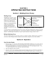
1
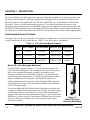
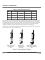
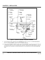
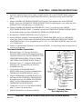
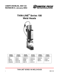
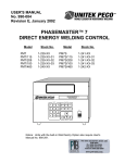
USER'S MANUAL 990-130
REVISION A, January 2002
THIN-LINE® Series 90
Weld and Reflow Solder Heads
Model 90F
MODEL
NUMBER
90F
90A
STOCK
NUMBER
2-150-XX
2-151-XX
Model 90A
MODEL
NUMBER
STOCK
NUMBER
MODEL
NUMBER
STOCK
NUMBER
90F/DT
90A/DT
2-150-XX-01
2-151-XX-01
90RF
90RA
2-150-XX-02
2-151-XX-02
Copyright © 1998, 2001 Unitek Miyachi Corporation
The engineering designs, drawings and data contained herein are the
proprietary work of UNITEK MIYACHI CORPORATION and may not be
reproduced, copied, exhibited or otherwise used without the written
authorization of UNITEK MIYACHI CORPORATION.
Printed in the United States of America.
REVISION RECORD
Revision
EO
Date
Basis of Revision
Original Release
A
19161
1/02
Added Unitek Peco™ name
THINLINE® SERIES 90 WELD AND REFLOW SOLDER HEADS
ii
990-130
FOREWORD
Thank you for purchasing a Unitek PecoTM THIN-LINE® SERIES 90 Weld Head.
Upon receipt of your equipment, please thoroughly inspect it for shipping damage before its installation.
Should there be any damage, please immediately contact the shipping company to file a claim, and notify us
at:
Unitek Miyachi Corporation
1820 South Myrtle Avenue
P.O. Box 5033
Monrovia, CA 91017-7133
Telephone: (626) 303-5676
FAX:
(626) 358-8048
e-mail:
[email protected]
The purpose of this manual is to supply operating, maintenance and service personnel with the information
needed to properly and safely operate and service the THIN-LINE® SERIES 90 Weld Heads.
We have made every effort to ensure that the information in this manual is accurate and adequate. Should
questions arise, or if you have suggestions for improvement of this manual, please contact us at the above
location/numbers.
Unitek Miyachi Corporation is not responsible for any loss due to improper use of this product.
THINLINE® SERIES 90 WELD AND REFLOW SOLDER HEADS
990-130
iii
CONTENTS
Revision Record.................................................................................................................................... ii
Foreword
....................................................................................................................................... iii
CHAPTER 1: DESCRIPTION......................................................................................................... 1-1
Section I. Features.......................................................................................................................... 1-1
Foot Actuated Series 90 Head...................................................................................................
Model 90F, In-line Electrode Weld Head...........................................................................
Model 90F/DT, Offset Electrode Weld Heads ...................................................................
Model 90RF, Reflow Soldering Head ................................................................................
Air Actuated Series 90 Heads ...................................................................................................
1-2
1-2
1-3
1-3
1-3
Section II. Accessories................................................................................................................... 1-5
CHAPTER 2: INSTALLATION ...................................................................................................... 2-1
Section I. Physical Installation....................................................................................................... 2-1
Foot Pedal Actuated Weld Heads .............................................................................................
Air Actuated Weld Heads .........................................................................................................
Additional Attachments ............................................................................................................
Solenoid Air Valve Power Connection...............................................................................
In-line Water Cooled Electrode Holders.............................................................................
Model HE2000WC, Offset Water Cooled Electrode Holders ............................................
Reducing the Length of the Support Base ..........................................................................
2-1
2-4
2-5
2-5
2-5
2-6
2-6
Section II. Connection to Power Source ........................................................................................ 2-6
General...................................................................................................................................... 2-6
90F, 90A, 90F/DT, and 90A/DT Weld Head Connections....................................................... 2-7
90RF and 90RA Soldering Head Connections ......................................................................... 2-8
Section III. Electrode and Thermode Installation .......................................................................... 2-8
90F and 90A Electrode Installation ..........................................................................................
90F/DT and 90A/DT Electrode Installation .............................................................................
90RF and 90RA Blade Thermode, Fixed Installation ..............................................................
90RF and 90RA Blade Thermode, Pivot Installation ...............................................................
90RF and 90RA Fold-up Thermode, Pivot Installation............................................................
2-8
2-9
2-9
2-10
2-11
CHAPTER 3: OPERATING INSTRUCTIONS ............................................................................. 3-1
Section I. Welding Force Theory................................................................................................... 3-1
Welding Force........................................................................................................................... 3-1
Reflow Soldering Force ............................................................................................................ 3-1
THINLINE® SERIES 90 WELD AND REFLOW SOLDER HEADS
iv
990-130
Section II. Operation...................................................................................................................... 3-1
Foot Actuated Heads................................................................................................................. 3-1
Air Actuated Heads................................................................................................................... 3-3
Downstop Adjustment ........................................................................................................ 3-4
CHAPTER 4: USER MAINTENANCE .......................................................................................... 4-1
Maintenance.................................................................................................................................... 4-1
Electrode Dressing .......................................................................................................................... 4-1
CHAPTER 5: SERVICE................................................................................................................... 5-1
Section I. Adjustments ................................................................................................................... 5-1
Linear Ball Bearing Bushing Adjustment.................................................................................
Anti-Rotation Yoke Adjustment ...............................................................................................
Tare Spring Adjustment............................................................................................................
Force Firing Switch Adjustment...............................................................................................
Minimum Firing Force..............................................................................................................
Spring Tube Bearings ...............................................................................................................
5-1
5-1
5-2
5-3
5-3
5-3
Section II. Disassembly/Re-assembly............................................................................................ 5-1
Electrode Holder Disassembly/Re-assembly............................................................................
Lower In-Line Electrode Holder Disassembly ...................................................................
Lower In-Line Electrode Holder Re-assembly ...................................................................
Upper In-line Electrode Holder Disassembly .....................................................................
Upper In-line Electrode Holder Re-assembly.....................................................................
5-4
5-4
5-4
5-5
5-5
Section III. Electrode/Thermode Holder Conversion .................................................................... 5-6
Offset Electrode Holder Conversion......................................................................................... 5-6
Thermode Holder Conversion................................................................................................... 5-7
Section IV. Repair Service............................................................................................................. 5-8
Telephone Service..................................................................................................................... 5-8
Factory Service Repair.............................................................................................................. 5-8
APPENDIX A: TECHNICAL SPECIFICATIONS ....................................................................... A-1
Specifications.................................................................................................................................. A-1
Outline Drawings ............................................................................................................................ A-2
THINLINE® SERIES 90 WELD AND REFLOW SOLDER HEADS
990-130
v
ILLUSTRATIONS
Figure
Title
Page
1-1
1-2
1-3
1-4
Model 90F In-line Electrode Weld Head............................................................................
Model 90F/DT Offset Electrode Weld Head ......................................................................
Model 90RF Thermode Adapter Reflow Soldering Head ..................................................
Air Actuated Series 90 Models ...........................................................................................
1-2
1-3
1-3
1-4
2-1
2-2
2-3
2-4
2-5
2-6
2-7
2-8
2-9
2-10
2-11
2-12
2-13
2-14
2-15
Model 90F and MSP Footpedal Installation .......................................................................
Series 90 Cutaway Illustrates Location and Size of Adjustment Screws ...........................
Solenoid Air Valve Assembly ............................................................................................
In-line Electrode Holder Modification for Water Cooling .................................................
Tubing Path for Water Cooling In-line Electrode Holder ..................................................
Water Cooled HE2000WC Offset Electrode Holders ........................................................
Bottom View of Support Base ............................................................................................
90F and 90A In-line Weld Head Connections....................................................................
90F/DT and 90A/DT Offset Weld Head Connections........................................................
90RF and 90RA Reflow Soldering Head Connections......................................................
In-line Electrode Holder Installation ..................................................................................
Offset Electrode Holder Installation ...................................................................................
Blade Thermode, Fixed Installation....................................................................................
Blade Thermode, Pivot Installation ....................................................................................
Fold-up Thermode, Pivot Installation .................................................................................
2-2
2-3
2-4
2-5
2-5
2-6
2-6
2-7
2-7
2-8
2-8
2-9
2-9
2-10
2-11
3-1
3-2
Welding Force (Pressure) Defect Diagram......................................................................... 3-1
Using a Force Gauge to Measure the Weld Firing Force ................................................... 3-2
5-1
5-2
5-3
5-4
5-5
5-6
5-7
Bearing Clearance Adjustment ...........................................................................................
Tare Spring Adjustment......................................................................................................
Firing Force Switch Adjustment.........................................................................................
Lower Electrode Disassembly ............................................................................................
Upper In-line Electrode Holder Exploded View ................................................................
Offset Electrode Holder Exploded View ............................................................................
Thermode Adapter Block Exploded View..........................................................................
A-1
A-2
Outline Drawings ................................................................................................................ A-2
UNIPULSE Welding Transformers.................................................................................... A-14
5-1
5-2
5-3
5-4
5-5
5-6
5-7
Tables
Table
1-1
1-2
A-1
Title
Page
Foot Actuated Model Features............................................................................................ 1-2
Air Actuated Model Features.............................................................................................. 1-4
Specifications...................................................................................................................... A-1
THINLINE® SERIES 90 WELD AND REFLOW SOLDER HEADS
vi
990-130
CHAPTER 1
DESCRIPTION
Section I: Features
Unitek Peco Thin-Line Series 90 Welding and Reflow Soldering Heads are precision, low inertia, forcefired designs with a narrow vertical profile. Depending on the model, their 3 inch width, 1 1/2 inch stroke, 7
to 100 or 150 pounds force range and 6 1/4 to 10 3/8 inch throat depth allows them to be used in a wide
variety of precision resistance welding and reflow soldering applications. The Series 90 is a "production
line" head. Bearing life is designed for a minimum of 10 million operations when used according to the
specifications. The diameter of the mounting post and the main shaft have been selected to ensure that the
electrodes do not "wipe" more than .001 inch at 150 pounds. This is an important consideration in critical
welding applications such as hermetic seals and pressure transducers. Series 90 Thin-Line Heads have six
mounting holes on the spine which allow them to be easily incorporated into custom welding machines.
The aluminum base of the Model 90 can be modified by the user in order to provide additional space to
accommodate custom fixtures and tooling. The Series 90 Head is available in three different electrode
configurations. Each configuration can be foot pedal or air actuated.
Unitek Peco Series 90 Heads excel in their ability to precisely place consistent, high quality welds, even in
complex welding applications. They feature low inertia, light weight designs which ensure fast dynamic
response. This allows the electrodes to follow the minute expansion and contraction of the weld joint as it
heats and cools. A "differential motion" Force-Firing System initiates the power source at the precise
moment when the Preset Firing Force is applied to the workpieces. Rugged construction, linear ball bearing
bushings and an over-sized, anti-rotation bearing system provide perfect in-line electrode travel which
assures smooth vertical travel of the upper electrode arm. This system minimizes the wiping action of the
electrodes during welding, even at maximum force settings.
The Firing force is continuously adjustable from a minimum of 7 to a maximum of 150 pounds using InLine Electrode Holders or Thermode Adapter Block and a maximum of 100 pounds using Offset Electrode
Holders. Settings are quickly reproduced by using the Force Adjustment Knob and easy-to-read visual
scale. An adjustable Tare Spring allows the user to compensate for the weight of non-standard electrode
holders. An adjustment screw is provided which allows the user to adjust the sensitivity of the Force Firing
Switch.
All Series 90 Heads have adjustable Up Stops and Down Stops. The Down Stop can be used to limit
excessive over-travel. The Up Stop can be used to reduce the stroke, and therefore the travel time, of the
Weld Head. The stroke of these Weld Heads should not be reduced to less than 1/4 inch, when used in
automated machines, in order to obtain long bearing life and ensure that the ball bearings recirculate
properly.
THINLINE® SERIES 90 WELD AND REFLOW SOLDER HEADS
990-130
1-1
CHAPTER 1: DESCRIPTION
The Terminal Block, Flexible Copper Strap and Upper Electrode Assembly are electrically insulated from
the frame of the Weld Head. The Frame, Support Post and Support Base are grounded to the bench top.
Electrode Holders for the Models 90F, 90A, 90F/DT, and 90A/DT use 1/4 inch diameter, ES0800 Series
Electrodes. These electrodes contain snap ring grooves. User ordered snap rings can be put on each
electrode to prevent slipping in the electrode holder whenever the welding force exceeds 100 pounds. The
Model ETB3 Table Electrode can be used with the Offset Electrode Holders. Models 90RF and 90RA use
the 17BW Series of Blade Thermodes and 17FW2187 Fold-up Thermode for reflow soldering applications.
Foot Actuated Series 90 Heads
Targeting of the work pieces is generally easier using foot actuation since foot actuation allows the operator
to easily control the rate of electrode descent. Table 1-1 lists the features of each model:
Table 1-1. Foot Actuated Model Features
Model
Stock Number Electrode Holder Electrode Type Application
90F
2-150-01
HEU90K
ES0800 series
Welding
90F/DT
2-150-01-01
HE90ABK
ES0800 series
Welding
90RF
2-150-01-02
HE90TAB
17BW or 17FW
Reflow
Model 90F, In-line Electrode Weld Head
The Model 90F, as shown in Figure 1-1, is a conventional opposed "InLine" electrode welding head. The mechanism in the Series 90 provides a
three-to-one mechanical advantage in addition to the three-to-one
advantage provided by the Model MSP Footpedal. This means that the
operator must apply approximately 17 pounds to the Footpedal in order to
obtain a welding force of 150 pounds. The Model 90F includes the
Linkage and Hardware Kit required to install the Model MSP Footpedal.
Also included are one pair of 1/4 inch diameter RWMA-2 Electrodes and
#2 AWG Welding Cables.
The In-Line Model HEU90 Electrode Holder Housings are designed with
cooling fins which radiate heat and reduce the necessity for forced cooling.
The Electrode Holders can be forced air or water cooled by drilling and
tapping a hole in the Housing as illustrated in Figure 13. In-Line Electrode
Holders use a collet to clamp 1/4 inch diameter, ESO800 Series Electrodes.
The Lower Electrode Assembly can be easily aligned with the Upper
Electrode Assembly.
Figure 1-1.
Model 90F In-line
Electrode Weld Head
THINLINE® SERIES 90 WELD AND REFLOW SOLDER HEADS
1-2
990-130
CHAPTER 1: DESCRIPTION
Model 90F/DT, Offset Electrode Weld Head
Figure 1-2 shows the Model 90F/DT which uses the HE90ABK Offset
Electrode Holder Block in both the upper and lower electrode position. The
offset configuration provides a throat depth of 10 3/8 inches. Welding force
is limited to 100 pounds.
The Model HE90ABK Offset Electrode Holder Block accepts 5/8 inch
diameter, Model HE2000 Electrode Holders, which use the 1/4 inch
diameter, ESO800 Series Electrodes. The Model HE2000 Electrode
Holders can by replaced with the Model HE2000WC Water Cooled
Electrode Holders.
Figure 1-2.
Model 90F/DT Offset
Electrode Weld Head
Model 90RF, Reflow Soldering Head
Reflow soldering ribbon cables or printed circuit connectors can
be accomplished by using the Model 90RF Reflow Soldering
Head with Blade Thermodes as shown in Figure 1-3.
The 17BW Series of Blade Thermodes can be mounted using
pivot or fixed mounting hardware attached to the Model
HE90TAB Thermode Adapter Block. The single 17FW2187
Fold-up Thermode only uses the pivot mounting hardware. See
Chapter 2, Section III for detailed thermode mounting
instructions.
Air Actuated Series 90 Heads
All Series 90 Foot Actuated Heads can be ordered with air actuation
Figure 1-3.
already installed. Air actuation makes it easier to incorporate the
Model 90RF Thermode Adapter
Series 90 Heads into automated systems. An air cylinder replaces
Reflow Soldering Head
the Model MSP Footpedal as the actuation source. The speed of the
air actuation system is limited by the speed at which the electrode
holder can move without damaging the electrodes, thermodes or workpieces as a result of the impact.
Welding rates of 1 per second are possible. Table 1-2 lists the features of each model, shown in Figure 1-4.
THINLINE® SERIES 90 WELD AND REFLOW SOLDER HEADS
990-130
1-3
CHAPTER 1: DESCRIPTION
Table 1-2. Air Actuated Model Features
Model
Stock Number Electrode Holder Electrode Type Application
90A
2-151-01
HEU90K
ES0800 series
Welding
90A/DT
2-151-01-01
HE90ABK
ES0800 series
Welding
90RA
2-151-01-02
HE90TAB
17BW or 17FW
Reflow
The top mounted 1 1/16 inch diameter Air Cylinder is supplied with two gauges, Pressure Regulators and
Flow Controls. The four-way Air Solenoid, which controls the direction of air flow to the Air Cylinder, is
available with either 24 (standard) or 115 VAC ratings. The Pressure Regulators and Flow Controls allow
independent adjustment of the up and downspeed of the upper electrode. The Solenoid and Regulator
Assembly is contained in a separate package that mounts on the spine of the Weld Head.
The Models 250, 500 and 800 Stored Energy Power Supplies require that the Model FSAC Footswitch be
used to energize the Four-Way Air Solenoid Valve.
Model 90A In-Line
Electrode Weld
Head
Model 90A/DT
Offset Electrode
Weld Head
Model 90RA Thermode
Adapter Reflow Soldering
Head
Figure 1-4. Air Actuated Series 90 Models
THINLINE® SERIES 90 WELD AND REFLOW SOLDER HEADS
1-4
990-130
CHAPTER 1: DESCRIPTION
The Phasemaster IV Time-At-Temperature Control (PM4), the Phasemaster series of direct energy welding
controls and the microprocessor controlled series of stored energy power supplies. Each of these controls or
power supplies has a 24/115 VAC Valve Output for energizing and controlling the timing of the Air
Solenoid Valve. The Model FS2L Footswitch is used to initiate all controls.
Section II: Accessories
Model
BLCS
DFS
ES0802
ES0803
ES0811
ES0813
ES0820
ES0850
ETB3
FG100
FG100KG
FG200
FSAC
FS2L
HE2000
HE2000WC
HE90ABK
HE90C
HE90TAB
HEL90K
HEU90K
MSP
OMAA90
Description
Microscope, .3X objective, 20X eyepieces, 4 to 18X magnification. Includes Arm and
Porthole Assembly.
Dual Firing Switch Junction Box. Connects two firing switch cables to a single power
source.
Electrode, RWMA-2, 1/4 inch diameter x 2 inches long.
Electrode, RWMA-3, 1/4 inch diameter x 2 inches long.
Electrode, RWMA-11, copper tungsten insert, 1/4 inch diameter x 2 inches long.
Electrode, RWMA-13, tungsten insert, 1/4 inch diameter x 2 inches long.
Electrode, RWMA-14, molybdenum insert, 1/4 inch diameter x 2 inches long.
Electrode, Glidcop, 1/4 inch diameter x 2 inches long.
3 inch Table Electrode, RWMA-2 for use with Offset Electrode Holders.
100 lb Electrode Force Gage. 1 lb x 100 lb scale.
100 kg Electrode Force Gage. 1 kg x 100 kg scale.
200 lb Electrode Force Gage. 2 lb x 200 lb scale.
Medium duty Single Level Footswitch which switches 115 VAC to air heads. Use with
Stored Energy Power Supplies.
Footswitch for controlling Phasemaster controls.
Electrode Holders, 5/8 inch diameter, 2 inch long. Holds 1/4 inch diameter electrodes.
Water/Air Cooled Electrode Holders, 5/8 inch diameter, 2 inch long. Holds 1/4 inch
diameter electrodes.
Offset Upper and Lower Electrode Adapter Blocks for 90F Weld Head. Not for use over 100
pounds. Includes Lower Electrode Mounting Post, 1 pair HE2000 Electrode Holders, 1 pair
ESO802 Electrodes and Hardware.
Collet and Nut Assembly for the Model 90 In-Line Electrode Holders.
Thermode Adapter Block for 90RF and 90RA Reflow Soldering Heads.
In-Line LOWER Electrode Holder Assembly for 90 Series Weld Head. Includes hardware.
In-Line UPPER Electrode Holder Assembly for 90 Series Weld Head. Includes hardware.
Medium Force Swing type Footpedal. Rated 100 pounds.
Allows the use of Model BLCS Microscope with Series 90 Heads.
THINLINE® SERIES 90 WELD AND REFLOW SOLDER HEADS
990-130
1-5
CHAPTER 1: DESCRIPTION
Model
PD
17BW1200
17BW2187
17BW2500
17FW2187
2AA16
570-2-040
325-1-119
Description
Polishing Disks, package of 50.
Blade Thermode, 1.20 inches wide x .060 inches thick, with thermocouple and air cooling
tube.
Blade Thermode, 2.18 inches wide x .060 inches thick, with thermocouple and air cooling
tube.
Blade Thermode, 2.50 inches wide x .060 inches thick, with thermocouple and air cooling
tube.
Fold-up Thermode, 2.18 inches wide x .060 inches thick, with thermocouple and air cooling
tube. Not for use over 350 C.
Welding Cable, #2, 16 inches long.
Retaining Ring for 1/4 inch diameter electrodes.
1/4 inch O.D. Plastic Tube Fitting with 1/4 NPT pipe thread. Use to convert HEL90K and
HEU90K In-Line Electrode Holders for water cooling.
THINLINE® SERIES 90 WELD AND REFLOW SOLDER HEADS
1-6
990-130
CHAPTER 2
INSTALLATION
Section I: Physical Installation
Foot Pedal Actuated Weld Heads
1
Position Mounting Template, located in the Ship Kit, in the desired location on the workbench. Make
certain that sufficient working space is provided from front edge of the bench to the Mounting Base.
This permits operator to use the bench as a support when positioning parts. Most applications require
about six to ten inches from edge of the bench to front of the Support Base.
NOTE: All dimensions use inches and all mounting hardware is American standard unless specified
otherwise.
2
Drill six 3/8 inch diameter mounting holes as shown on the Mounting Template. Drill the 2.00 DIA.
hole for all models. Drill the 1.25 DIA hole for the Model 90F/DT.
CAUTION: Use a 1/4 inch hex driver to tighten the support post locking screws location on the back of the
right side of the support base to ensure that the weld head does not slip and pinch your fingers!
NOTE: All mounting hardware such as screws, lock washers, and washers are contained in the Ship Kit.
3
Reference Figure 2-1 for the following instructions. Remove the PEDAL ACTUATOR, item [1], by
removing the BELLCRANK NUT, item [2], and the BELLCRANK BOLT, item [3].
4
Remove the BUSHING BOLT, item [4], and BUSHING WASHER, item [5].
5
Remove the BELLCRANK SPRING, item [6]. Slip the BUSHING, item [7], inside the BELLCRANK
SPRING, replace the BELLCRANK SPRING and secure in position using the BUSHING WASHER
and BUSHING BOLT.
6
Slide the EXTENSION ARM, item [8], over the end of the Bellcrank Arm and secure with two 10-32 X
3/4 CAP HEAD SCREWS, item [9].
NOTE: The middle screw must pass through the clearance hole in the Bellcrank Arm.
7
Line up the weld head with the correct holes in the Mounting Template. CAUTION: Be careful not to
bend the LINK ASSEMBLY, item [18]. Attach the SPACER PLATE, item [10], to the
WORKBENCH, item [11], using two 5/16-18 x 2 3/4 CAP HEAD SCREWS, item [13], LOCK
WASHERS, item [14], and WASHERS, item [15]. NOTE: The CAP HEAD SCREWS must pass
through the SPACER PLATE and WORKBENCH and thread into the two rear mounting holes on the
weld head support base.
8
Attach the FOOTPEDAL MOUNTING PLATE, item [12] to the SPACER PLATE, item [10], using
two 5/16-18 x 3/4 HEX HEAD SCREWS, item [16], ITL WASHERS, item [17], and WASHERS, item,
[15].
THINLINE® SERIES 90 WELD AND REFLOW SOLDER HEADS
990-130
2-1
CHAPTER 2: INSTALLATION
Figure 2-1. Model 90F and MSP Footpedal installation
9
Secure the front of the weld head to the WORKBENCH using two 5/16-18 x 2 HEX HEAD BOLTS,
item 21, LOCK WASHERS, item [14], and WASHERS, item [15].
10 Connect the EXTENSION ARM, item [8], to the LINK ASSEMBLY, item [18] using the 10-32 X 1.00
CAP HEAD SCREW, item [19], and KEP NUT, item [20]. The ADAPTER ARM should be parallel to
the bottom of the work bench. Re-attach the PEDAL ACTUATOR and set it to the desired operating
angle.
THINLINE® SERIES 90 WELD AND REFLOW SOLDER HEADS
2-2
990-130
CHAPTER 2: INSTALLATION
Figure 2-2. Series 90 Cutaway Illustrates Location and Size of Adjustment Screws
THINLINE® SERIES 90 WELD AND REFLOW SOLDER HEADS
990-130
2-3
CHAPTER 2: INSTALLATION
Air Actuated Weld Heads
1
Position Mounting Template, Figure 43, in the desired location on the workbench. Make certain that
sufficient working space is provided from the front edge of bench to the Support Base. This permits
operator to use the bench as a support when positioning parts. Most applications require about six to
ten inches from edge of the bench to front of the Support Base.
2
Drill six 3/8 inch diameter mounting holes as shown on the Mounting Template. Drill the 2.00 DIA.
hole for all models. Drill the 1.25 DIA hole for the Model 90A/DT.
NOTE: All mounting hardware such as screws, lock washers, and washers are contained in the Ship Kit.
3
Reference Figure 2-2 for the following instructions.
CAUTION: use a 1/4 inch hex driver to tighten the support post locking screws location on the back of the
right side of the support base to ensure that the weld head does not slip and pinch your fingers!
4
Align the SUPPORT BASE, item [11], over the mounting holes. Attach the SUPPORT BASE to the
workbench using four 5/16-18 x 1 1/2 inch hex head bolts with lock washers and washers (not shown)
to secure the front and rear of the SUPPORT BASE.
5
Reference Figure 2-3 for the following instructions. Insert a 0.25 inch outside diameter plastic hose,
with a rated burst pressure of 250 psi, into
the AIR INPUT, item [6], located on the
bottom of the Solenoid Air Valve
Assembly. The AIR INPUT uses a "quick
release" connector so specials tools are not
needed. Simply push the hose into the
"quick release" fitting as far as it will go.
Connect the other end to a FILTERED AIR
SUPPLY (100 psig maximum). UNITEK
suggests that in-line lubricators not be used
since excess oil can blow-by worn seals in
the AIR CYLINDER, item [1], ending up
on the workpieces. Every one million
cycles, the user should put a few drops of
oil in the AIR CYLINDER. The tubing
connecting the TOP AIR PRESSURE
REGULATOR, item [4], with the
UPSPEED AIR FLOW VALVE, item [2],
and BOTTOM AIR PRESSURE
REGULATOR, item [5], with the
DOWNSPEED AIR FLOW VALVE, item
[3], has been pre-assembled at the factory.
Figure 2-3. Solenoid Air Valve Assembly
THINLINE® SERIES 90 WELD AND REFLOW SOLDER HEADS
2-4
990-130
CHAPTER 2: INSTALLATION
6
When dressing electrodes, the TOP AIR PRESSURE REGULATOR must be turned down. An
auxiliary regulator, or a customer supplied bleeder valve connected to output of the of the TOP AIR
PRESSURE REGULATOR, can also be used to lower air pressure to facilitate dressing the electrodes.
Additional Attachments
Solenoid Air Valve Power Connection
Stored Energy Power Supplies require a 115 VAC Solenoid
Air Valve Assembly for plugging directly into a Model
FSAC Foot Switch receptacle.
7500A - Both the 115 VAC and 24 VAC Solenoid Valve
Assemblies plug directly into the 115 VAC receptacle on the
back of the 7500A. An internal switch, set by the user,
applies 115 or 24 VAC to the receptacle.
PHASEMASTER (TM) Controls - The 115 VAC Solenoid
Air Valve Assembly plugs directly into the 115 VAC
VALVE receptacle on the rear panel. The 24 VAC Solenoid
Valve Assembly requires that the user replace the 115 VAC
connector with the 24 VAC connector provided in the
Phasemaster Shipping Kit. The new connector plugs into the
24 VAC VALVE located on the rear panel.
Install the system in accordance with established safety
practices and standards. Anti-Tie-Down Palm Buttons are
not usually required if the electrode spacing is insufficient to
allow the operator's fingers to fit between them.
Figure 2-4. In-line Electrode
Holder Modification for Water
Cooling
In-line Water Cooled Electrode Holders
If forced cooling is required, drill a .399 inch diameter hole
in the Upper and Lower In-Line Electrode Holder as shown
in Figure 2-4. Tap a 1/4 NPT standard pipe thread into both
ends of the hole.
Order four 1/4 inch O.D. Plastic Tube Fittings from Unitek
Peco (P/N 325-1-119). Apply pipe sealant to each tread and
then thread two fittings into the Upper and Lower Electrode
Holders. Connect 1/4 inch O.D. plastic tubing to the fittings
as shown in Figure 2-5. Support the tubing on the Upper InLine Electrode Holder using a cable clamp placed under one
of the weld head side cover screws. Be sure to leave an
adequate service loop.
Figure 2-5. Tubing Path for
Water Cooling In-line Electrode
Holder
THINLINE® SERIES 90 WELD AND REFLOW SOLDER HEADS
990-130
2-5
CHAPTER 2: INSTALLATION
Model HE2000WC, Offset Water Cooled Electrode Holders
Models 90A/DT and 90F/DT use the HE90ABK Offset Electrode
Holders which in turn use Model HE2000, 5/8 inch diameter by 3
3/4 inch long, solid electrode holders for extending the weld head
throat depth. In those applications where the duty cycle approaches
10 percent or where the electrodes are too hot to comfortably touch,
the HE2000WC Water Cooled Electrode Holders should be used in
place of the solid HE2000 holders. Electrode life is inversely
proportional to Electrode Temperature. These holders can be
cooled by connecting them to an air supply or a water supply as
illustrated in Figure 2-6.
Figure 2-6. Water Cooled
HE2000WC Offset Electrode
Holders
Reducing the Length of the Support Base
The Support Base can be cut to provide additional room for
tooling. It can be reduced to 5.5 inch by cutting the Base just in
front of the support web that contains the mounting holes, as
shown in Figure 2-7.
Figure 2-7. Bottom View of
Support Base
Section II: Connection to Power Source
General
The Series 90 Heads come with the necessary fastening hardware for connecting the Welding already
installed on the weld head power straps. The hardware for connecting the other end of the Welding Cables
to the Power Supply or Welding Transformer can be found in the Power Supply or Welding Transformer
Ship Kit.
THINLINE® SERIES 90 WELD AND REFLOW SOLDER HEADS
2-6
990-130
CHAPTER 2: INSTALLATION
Connect the Weld Head Firing Switch Cable to the Firing Switch Receptacle located on the front panel of
all Stored Energy Power Supplies or to the matching connector/cable found on all Direct Energy Power
Supplies.
90F, 90A, 90F/DT, and 90A/DT Weld Head Connections
1
Reference Figures 2-8 AND 2-9. Position the Power Supply or Welding Transformer approximately 4
to 5 inch behind the Weld Head. Connect one 16 inch WELDING CABLE to the left side of the
WELD HEAD POWER STRAP using a 5/16-18 x 1/2 CAP HEAD SCREW. The FLAT WASHER
goes between the CAP HEAD SCREW and the WELDING CABLE terminal.
2
Connect the second WELDING CABLE to the left side of the LOWER ELECTRODE HOLDER using
a 5/16-18 x 1/2 CAP HEAD SCREW. The FLAT WASHER goes between the CAP HEAD SCREW
and the WELDING CABLE terminal.
3
Connect the opposite ends of each WELDING CABLE to the Power Supply or Welding Transformer
using the hardware supplied with the Welding Transformer Ship Kit. The hardware is sized for each
WELDING TRANSFORMER.
NOTES:
Do not put a flat or lock washer between the welding cable and the power terminal.
Be sure to place both cables on the same side of the support post. Failure to do so could dramatically
increase the amount of energy required to make a satisfactory weld because of added inductive losses
caused by the support post.
For the same reason, do not run welding cables through a steel workbench.
Figure 2-8. 90F and 90A In-line Weld
Head Connections
Figure 2-9. 90F/DT & 90A/DT Offset Weld
Head Connections
THINLINE® SERIES 90 WELD AND REFLOW SOLDER HEADS
990-130
2-7
CHAPTER 2: INSTALLATION
90RF and 90RA Reflow Soldering Head Connections
1
Reference Figure 2-10. Position the Power Supply or Welding Transformer approximately 4 to 5 inch
behind the Weld Head. Connect one 16 inch WELDING CABLE to the left side of the WELD HEAD
POWER STRAP using a 5/16-18 x 1/2 CAP HEAD SCREW. The FLAT WASHER goes between the
CAP HEAD SCREW and the WELDING CABLE terminal.
2
Connect the second WELDING CABLE to the right side of the POWER STRAP using a 5/16-18 x 1/2
CAP HEAD SCREW. The FLAT WASHER goes between the CAP HEAD SCREW and the
WELDING CABLE terminal.
3
Connect the opposite ends of each WELDING
CABLE to the Power Supply or Welding
Transformer using the hardware supplied with
the Welding Transformer Ship Kit. The
hardware is sized for each REFLOW
SOLDERING TRANSFORMER.
NOTES:
Do not put a flat or lock washer between the
welding cable and the power terminal.
Do not run welding cables through a steel
workbench.. Doing so could dramatically increase
the amount of energy required to make a
satisfactory weld because of added inductive losses
caused by the table.
Figure 2-10. 90RF and 90RA Reflow
Soldering Head Connections
Section III: Electrode and Thermode Installation
90F and 90A Electrode Installation
Verify that the COLLET is loose by turning it in the counter-clockwise direction.
Insert the electrode into the COLLET. Tighten by turning clockwise as shown in
Figure 2-11. Check the alignment of the electrodes. Loosen the three cap head
screws holding the LOWER IN-LINE ELECTRODE HOLDER
ASSEMBLY, re-align the holder, and then tighten the screws.
Figure 2-11. In-line
Electrode Holder
installation
THINLINE® SERIES 90 WELD AND REFLOW SOLDER HEADS
2-8
990-130
CHAPTER 2: INSTALLATION
90F/DT and 90A/DT Electrode Installation
Loosen the 10-32 CAP HEAD SCREW on the side of the HE2000 ELECTRODE
HOLDER. Insert the electrode into the holder. Tighten by turning clockwise as
shown in Figure 2-12. Check the alignment of the electrodes. Loosen the cap
head screw in the SUPPORT BASE and then rotate the LOWER OFFSET
ELECTRODE HOLDER ASSEMBLY into alignment with the upper electrode.
Tighten the cap head screw.
Figure 2-12. Offset
Electrode Holder
installation
90RF and 90RA Blade Thermode, Fixed Installation
1
Reference Figure 2-13. Verify that the THERMODE ADAPTER BLOCK, item [1], has two separate
WELD TERMINALS, item [2] and [3]. The INSULATOR PLUG, item [4], should be positioned
between the THERMODE ADAPTER BLOCK and both WELD TERMINALS. Attach the BLADE
THERMODE, item [5] to the WELD TERMINALS using two 8-32x1/4 CAP HEAD SCREWS, item
[6], and #8 ITL WASHERS, item [7]. Leave the screws loose.
Figure 2-13. Blade Thermode, Fixed Installation
2
Reference Chapter 3 for operating instructions. Bring the BLADE THERMODE down onto the
workpiece.
CAUTION: do not heat the thermode at this time or the loose screws will weld to the thermode and/or weld
straps.
3
While applying pressure against the workpiece, tighten each 8-32x1/4 CAP HEAD SCREW. This
action will ensure that the bottom of the BLADE THERMODE is parallel to the workpiece.
THINLINE® SERIES 90 WELD AND REFLOW SOLDER HEADS
990-130
2-9
CHAPTER 2: INSTALLATION
90RF and 90RA Blade Thermode, Pivot Installation
1
Reference Figure 2-4. Verify that the THERMODE ADAPTER BLOCK, item [1], has a single
separate WELD TERMINAL, item [2].
Figure 214. Blade Thermode, Pivot Installation
2
Assemble items [3] through [10] in numerical order.
NOTE: the convex surface of both BELLEVILLE WASHERS, item [8], must be placed against the face of
the INSULATOR WASHER, item [9].
3
Attach the Blade Thermode Pivot Assembly to the THERMODE ADAPTER BLOCK using the single
10-32x7/8 CAP HEAD SCREW, item [3].
CAUTION: Tighten this screw securely or it will weld to the THERMODE ADAPTER BLOCK.
4
Attach the BLADE THERMODE, item [11] to the WELD TERMINALS using two 8-32x1/4 CAP
HEAD SCREWS, item [12], and #8 ITL WASHERS, item [13].
CAUTION: Tighten both screws securely or they will weld to the THERMODE PIVOT MOUNTS.
THINLINE® SERIES 90 WELD AND REFLOW SOLDER HEADS
2-10
990-130
CHAPTER 2: INSTALLATION
90RF and 90RA Fold-Up Thermode, Pivot Installation
1
Reference Figure 2-15. Verify that the THERMODE ADAPTER BLOCK, item [1], has a single
separate WELD TERMINAL, item [2].
Figure 2-15. Fold-up Thermode, Pivot Installation
2
Assemble items [3] through [6] in numerical order.
3
Place the convex surface of both BELLEVILLE WASHERS, item [7], against the face of the
INSULATOR WASHER, item [8]. Slip this "Belleville Sandwich" between the top sides of the FOLDUP THERMODE, item [9].
4
Attach the Fold-up Thermode Pivot Assembly to the THERMODE ADAPTER BLOCK using the
single 10-32x7/8 CAP HEAD SCREW, item [3].
CAUTION: Tighten this screw securely or it will weld to the THERMODE ADAPTER BLOCK.
THINLINE® SERIES 90 WELD AND REFLOW SOLDER HEADS
990-130
2-11
CHAPTER 3
OPERATING INSTRUCTIONS
Section I: Welding Force Theory
Welding Force
Welding Force (Pressure) is a key
variable in the resistance welding
process. Excessive or insufficient
welding force or pressure can
cause a weak weld as shown in
Figure 3-1. For more information
on the basics of resistance
welding, a handbook entitled,
"Fundamentals of Resistance
Welding" is available from Unitek
Miyachi.
Excessive
Pressure
Overheating of Weldment
Weak Weld
Insufficient Nugget
Metal Expulsion
Warping
Insufficient
Pressure
Decoloration
Electrode Damage
Figure 3-1. Welding Force (Pressure) Defect Diagram
A certain amount of experimentation is necessary to achieve the proper Welding Force setting for a specific
application. Larger parts require higher force. The greater the diameter of electrode face, the higher force
required. Generally higher electrode force requires a greater amount of energy to make a weld.
Reflow Soldering Force
The reflow soldering process is not as force sensitive as resistance welding. Sufficient force or pressure is
necessary to ensure adequate thermal conduction and to hold the workpieces as the solder solidifies.
Section II: Operation
Foot Actuated Heads
1
Reference Figure 2-2. Rotate the WELD FORCE ADJUSTMENT KNOB, item [3], located on the top
of the Weld Head, clockwise to increase the Welding Force and counterclockwise to decrease force.
The maximum Welding Force is reached when the indicator reads "10" at the bottom of scale. "4" or
"5" on the Welding Force Scale represents a good initial setting.
2
Check the alignment of the electrodes.
3
Adjust the vertical work opening by either lowering the height of the lower Offset Electrode Holder or
by lowering the position of the SUPPORT POST in the SUPPORT BASE using a 1/4 inch hex key.
THINLINE® SERIES 90 WELD AND REFLOW SOLDER HEADS
990-130
3-1
CHAPTER 3: OPERATING INSTRUCTIONS
NOTE: The vertical work opening must be less than 1.5 inch (3.8
cm) or the weld head firing switch may not function properly.
4
As the actual Welding Force may vary slightly between similar
weld heads due to manufacturing tolerances, we recommend that
a Force Gage be used to precisely measure the Welding Force at
which the Power Supply is triggered.
5
Figure 3-2 shows how a Unitek Peco Force Gauge can be used to
set-up and measure the actual Welding Force . Force Gauges are
available in 100 lbs.(FG100), 200 lbs. (FG200), and 100 Kgs.
(FG100KG) models.
Figure 3-2. Using a Force
Gauge to Measure the Weld
Firing Force
6
Set the WELD or HEAT Switch on all PHASEMASTER and
7500A Direct Energy Power Supplies to the "OFF" position. Set the POWER Switch on Stored Energy
Power Supplies to the "OFF" position.
7
Disconnect the Weld Head Firing Switch Cable from the Power Supply.
8
Adjust the Weld Head Electrode spacing so that a UNITEK Force Gauge just fits between the
electrodes.
NOTE: The maximum opening must be less than 1.5 inches (3.8 cm).
9
Reference Figure 2-2. Turn the DOWNSTOP ADJUSTMENT SCREW, item [2], fully counterclockwise. This will allow maximum downward travel of the Upper Electrode.
10 Depress the Footpedal and note the force indication on the Force Gauge when the Firing Switch inside
of the Weld Head "clicks", then release the Footpedal. If the Firing Switch closure is inaudible, it is
easily detected by connecting an Ohmmeter or continuity checker to the Firing Switch Connector pins.
11 Reconnect the Weld Head Firing Switch Cable, turn on the WELD or HEAT Switch on all
PHASEMASTER and 7500A Direct Energy Power Supplies, and switch on Stored Energy Power
Supplies.
12 Make several welds. If the welding application requires more Welding Force, as typically indicated by
heavy electrode or workpiece sparking, increase the Welding Force and re-measure.
13 If the welding application requires less Welding Force, as indicated by heavy electrode marking
accompanied by a cold weld, decrease the Welding Force and re-measure.
THINLINE® SERIES 90 WELD AND REFLOW SOLDER HEADS
3-2
990-130
CHAPTER 3: OPERATING INSTRUCTIONS
Air Actuated Heads
1
This system should be installed in accordance with your established safety standards. Anti-Tie-Down
Palm Buttons are not usually required if the electrode spacing is not sufficient to allow the operator's
fingers to fit between them.
2
Review Air Actuated Weld Heads and Solenoid Air Valve Power Connections, in Chapter 2,
Installation, to verify that the air lines and solenoid power cord have been correctly installed.
3
It is very important to adjust the Bottom Air Pressure Regulator to a pressure level that just triggers the
Firing Switch in the Weld Head. Proper adjustment of the Bottom Air Pressure ensures that the Actual
Welding Force, as experienced by the workpieces, will be identical to the user Set Welding Force. The
typical user mistake is to set the Bottom Air Pressure at maximum for the fastest electrode travel. This
action results in inconsistent welds, workpiece and electrode damage.
4
Set the WELD or HEAT Switch on all PHASEMASTER and 7500A Direct Energy Power Supplies to
the "OFF" position. Set the POWER Switch on Stored Energy Power Supplies to the "OFF" position.
5
Set all PHASEMASTER Power Supplies to the BEAT/NON BEAT or ABORT ON Footswitch
Operating Mode and 1-LEVEL or 2-LEVEL.
6
Disconnect the Weld Head Firing Switch Cable from the Power Supply.
7
Adjust the Weld Head Electrode spacing so that a UNITEK Force Gauge just fits between the
electrodes.
NOTE: The maximum opening must be less than 1.5 inches (3.8 cm).
8
Reference Figure 2-2. Using the WELD FORCE ADJUSTMENT KNOB, set the Weld Force Indicator
to an initial setting of "4".
9
Turn the DOWNSTOP ADJUSTMENT SCREW, item [2], fully counter-clockwise. This will allow
maximum downward travel of the Upper Electrode.
10 Reference Figure 2-3. Close, but do not tighten, the UPSPEED AIR FLOW VALVE, item [2], and the
DOWNSPEED AIR FLOW VALVE, item [3]. Re-open both valves 3 to 4 turns.
11 Set the BOTTOM AIR PRESSURE REGULATOR, item [5], and the TOP AIR PRESSURE
REGULATOR, item [4] to 15 Psig.
12 Cycle the Weld Head by depressing and releasing the Footswitch. Adjust the UPSPEED AIR FLOW
VALVE located at the top of the AIR CYLINDER, item [1], so that the Upper Electrode moves upward
at a reasonable rate. It should not move so rapidly that it slams against the Upstop.
13 Insert a Force Gauge between the electrodes as shown in Figure 3-2. Depress and hold the Footswitch.
If the Firing Switch does not close, turn the TOP AIR PRESSURE REGULATOR clockwise until the
Firing Switch "clicks". Note the force indication on the Force Gauge when the Weld Head Firing
Switch "clicks" and then release the Footswitch. If the Firing Switch closure is inaudible, it is easily
detected by connecting an Ohmmeter or continuity checker to the Firing Switch Connector pins. If
THINLINE® SERIES 90 WELD AND REFLOW SOLDER HEADS
990-130
3-3
CHAPTER 3: OPERATING INSTRUCTIONS
more Welding Force is needed, go to Step 14. If less Welding Force is required, go to Step 15.
14 Reference the force reading from Step 13 as the starting point. If more Welding Force is required, turn
the WELD FORCE ADJUSTMENT KNOB clockwise and then increase the TOP AIR PRESSURE
REGULATOR setting until the Firing Switch closes. Repeat this trial and error process until the
desired Welding Force is reached. To provide the most sensitive DOWNSPEED AIR VALVE control,
the BOTTOM AIR PRESSURE REGULATOR setting should be within 15 to 20 Psig of the TOP AIR
PRESSURE REGULATOR Psig final setting.
15 Reference the force reading from Step 13 as the starting point. If less Welding Force is required, turn
the WELD FORCE ADJUSTMENT KNOB counter-clockwise and then decrease the TOP AIR
PRESSURE REGULATOR setting until the Firing Switch opens. Slowly increase the TOP AIR
PRESSURE REGULATOR setting until the Firing Switch just re-closes. Repeat this trial and error
process until the desired Welding Force is reached. To provide the most sensitive DOWNSPEED AIR
VALVE control, the BOTTOM AIR PRESSURE REGULATOR setting should be within 15 to 20 Psig
of the TOP AIR PRESSURE REGULATOR Psig final setting.
16 Readjust both the TOP AIR FLOW and BOTTOM AIR FLOW VALVES to provide smooth Upper
Electrode motion.
CAUTION: Using the air pressure regulators to control electrode speed can result excess welding force
being applied to the workpieces.
17 Readjust the electrodes in their holders as necessary to accommodate the actual workpiece.
18 Reconnect the Weld Head Firing Switch Cable to the Power Supply.
Downstop Adjustment
1
The DOWNSTOP ADJUSTMENT should only be used to prevent excessive workpiece
deformation. In most applications use of the DOWNSTOP ADJUSTMENT is unnecessary.
2
Depress and hold the Footswitch, closing the electrodes on the workpiece. Loosen the JAM NUT at
the base DOWNSTOP ADJUSTMENT SCREW. Rotate the DOWNSTOP ADJUSTMENT
SCREW until it just "bottoms out".
3
Release the Footswitch and then turn the DOWNSTOP ADJUSTMENT SCREW counter-clockwise
one or two turns to allow for electrode wear.
4
Do not attempt to use the DOWNSTOP ADJUSTMENT to limit the Welding Force. Doing so will
cause inconsistent weld quality.
THINLINE® SERIES 90 WELD AND REFLOW SOLDER HEADS
3-4
990-130
CHAPTER 4
USER MAINTENANCE
Maintenance
Series 90 Weld Heads are designed to minimize routine maintenance. Daily maintenance should be limited
to electrode dressing and cleaning.
Procedures for changing electrodes and thermodes are contained in Chapter 2, Section III, Electrode and
Thermode Installation
Electrode Dressing
1
Depending on use, periodic tip resurfacing is required to remove oxides and welding debris from
electrodes.
2
Set the WELD or HEAT Switch on all PHASEMASTER and 7500A Direct Energy Power Supplies to
the "OFF" position. Set the POWER Switch on Stored Energy Power Supplies to the "OFF" position.
3
Cleaning of the electrodes on production line should be limited to use of #400 - 600 grit emery paper.
In addition, the emery paper should have a solid backing so that it will not distort flat electrode
surfaces.
4
Reference Figure 2-3. Temporarily reduce the TOP AIR PRESSURE. Place the emery paper between
the electrodes and actuate the Footpedal or Footswitch to bring the electrodes into light contact with
paper. Move the paper in a rotary motion.
5
Wipe the electrode tips so that they are clean.
THINLINE® SERIES 90 WELD AND REFLOW SOLDER HEADS
990-130
4-1
CHAPTER 5
SERVICE
Section I: Adjustments
Linear Ball Bearing Bushing Adjustment
CAUTION: Do not adjust bearings unless the side play in the shaft exceeds 0.001 inch. Do not overtighten the bearings. If you can feel the balls move as the shaft is moved, the bearings are too tight! This
will dramatically reduce bearing life!
1
Remove the Covers from both sides of Weld Head
with a 1/8 inch hex key. Use a 1/8 inch hex key to
loosen the two BEARING CLEARANCE
ADJUSTMENT SCREWS on each side of the
UPPER and LOWER BEARINGS. If necessary,
realign each BEARING so that the BEARING split
faces forward as indicated in Figure 5-1. If the
BEARINGS will not turn easily, it can be assumed
that the bearings are correctly oriented.
2
Carefully tighten the BEARING CLEARANCE
ADJUSTMENT SCREWS to reduce bearing play.
The object of this adjustment is to reduce the lateral
movement of the Main Shaft while maintaining
smooth, low friction operation.
Figure 5-1. Bearing Clearance
Adjustment
Anti-Rotation Yoke Adjustment
1
Anti-Rotational play in upper the Electrode Arm Assembly is controlled by the ANTI-ROTATION
ADJUSTMENT, item [9], in Figure 2-2. Use a 5/32 inch hex wrench to adjust the YOKE. Turn the
WELD FORCE ADJUSTMENT KNOB fully counter-clockwise to the minimum force position.
2
Move the Upper Electrode Assembly slowly up and down by actuating the Footpedal or Footswitch.
Tighten the YOKE until both ANTI-ROTATION BEARINGS start to turn, without skidding, as the
YOKE is moved so that the Upper Electrode travels at least 1 inch.
3
Loosen the YOKE 1 turn. One of the ANTI-ROTATION BEARINGS should stop turning or start to
skid. Re-tighten the YOKE until both ANTI-ROTATION BEARINGS just stop skidding. The ANTIROTATION BEARINGS should just barely touch the ANTI-ROTATION ALIGNMENT SHAFT.
THINLINE® SERIES 90 WELD AND REFLOW SOLDER HEADS
990-130
5-1
CHAPTER 3: OPERATING INSTRUCTIONS
Tare Spring Adjustment
1
Reference Figure 2-2. Set the WELD FORCE ADJUSTMENT KNOB fully counter-clockwise to
minimum. Place the Weld Head in a vertical position. The UPPER ELECTRODE ASSEMBLY, item
[17], and the Upper Electrode must be in place to adjust the TARE SPRING, item [7].
2
Adjust the TARE SPRING using a 3/16 inch hex key. The TARE SPRING ADJUSTMENT SCREW is
recessed in the Center of the SPRING TUBE PLUG (not shown) on the bottom of the Weld Head.
Adjust the TARE SPRING ADJUSTMENT SCREW until the bottom edge of the GUIDE ARM
ASSEMBLY, item [15], reaches its lowest point. Mark this position on the SPRING TUBE YOKE,
item [16].
3
Turn the TARE SPRING ADJUSTMENT SCREW clockwise until the GUIDE ARM ASSEMBLY
moves up from its lowest point by .06 to .09 inches (1.5 to 2.3 mm) as shown in Figure 5-2.
Figure 5-2. Tare Spring Adjustment
THINLINE® SERIES 90 WELD AND REFLOW SOLDER HEADS
5-2
990-130
CHAPTER 3: OPERATING INSTRUCTIONS
Force Firing Switch Adjustment
1
Reference Figures 2-2 and 5-3. Set the WELD FORCE ADJUSTMENT KNOB fully counterclockwise (minimum Welding Force).
Correct Actuation Lever position
Incorrect Actuation Lever position,
lever hits the switch body
Figure 5-3. Firing Force Switch Adjustment
2
Adjust the FIRING FORCE SENSITIVITY ADJUSTMENT SCREW, item [8], with a 9/64 inch hex
wrench so that Actuation Lever on Firing Switch is horizontal as shown in Figure 5-3.
3
Set the WELD FORCE ADJUSTMENT KNOB fully clockwise (maximum Welding Force. The
Actuation Lever should not touch the body of the Firing Switch.
Minimum Firing Force
The minimum Welding Force at which the Firing Switch closes is 7 lbs. If the Welding Head fails to meet
this specification, repeat the above four adjustments.
Spring Tube Bearings
The bearings which guide the SPRING TUBE YOKE, item [16], Figure 2-2, are bronze bushings with a
Teflon/lead bearing surface. During normal operation, these bearings quickly seat and transfer a small
amount of material, an average of 0.0005 inch (0.013 mm) thick, to the tube housing, forming a physically
bonded, gray-green lubricant film. The rubbing surface of the Bronze Bushing also acquires a gray-green
color as the Teflon/lead coating wears. Any excess of the Teflon/lead surface layer will be shed as fine,
feathery particles.
Following the break-in period, the wear rate becomes extremely low. The Bronze Bushings should last at
least 10 million operations. After an extended period of operation, the wear rate increases as the Bronze
Bushings approach the end of their useful life as a self-lubricating bearings. When the radial wear exceeds
0.0025 inch (0.064 mm), replace both Bronze Bushings.
THINLINE® SERIES 90 WELD AND REFLOW SOLDER HEADS
990-130
5-3
CHAPTER 3: OPERATING INSTRUCTIONS
Section II: Disassembly/Re-assembly
Electrode Holder Disassembly/Re-assembly
Lower In-line Electrode Holder Disassembly
1
Reference Figure 5-4. Remove the Lower Electrode from the ELECTRODE COLLET NUT, item
[1].
Figure 5-4. Lower Electrode Disassembly
2
Remove all three 10-32 x 5/8 CAP HEAD SCREWS, item [2], #10 ITL WASHERS, item [3], and
#10 FLAT WASHERS, item [4].
3
Lift the LOWER IN-LINE ELECTRODE HOLDER, item [5], from the BASE SUPPORT.
4
Remove all three 8-32 x 3/8 CAP HEAD SCREWS, item [6], from the ELECTRODE HOLDER
BASE, item [7], to separate the LOWER IN-LINE ELECTRODE HOLDER from the
ELECTRODE HOLDER BASE.
Lower In-line Electrode Holder Re-assembly
To re-assemble the LOWER IN-LINE ELECTRODE HOLDER, reverse the above disassembly
procedure.
THINLINE® SERIES 90 WELD AND REFLOW SOLDER HEADS
5-4
990-130
CHAPTER 3: OPERATING INSTRUCTIONS
Upper In-line Electrode Holder Disassembly
CAUTION: Turn the flange, not the housing, of the upper
electrode assembly in order to remove it.
1
Reference Figure 2-2. Remove the Upper Electrode from
the ELECTRODE COLLET NUT, item [5].
2
Actuate the Weld Head and hold in the down position.
Adjust the UPSTOP, item [1], so that the top of the
UPPER IN-LINE ELECTRODE HOLDER , item [17], is
approximately 1.5 inches (4 cm) from the bottom of the
Weld Head Casting.
3
Remove the COPPER FLEXURE, item [19], using a 3/16
inch hex key to remove the socket head screws and brass
washers which hold the COPPER FLEXURE to the
UPPER IN-LINE ELECTRODE HOLDER.
4
Reference Figure 5-5. Remove the ELECTRODE
HOLDER COLLET NUT, item [16], from the UPPER
IN-LINE ELECTRODE HOLDER, item [13].
5
Use a large wrench to hold the UPPER IN-LINE
ELECTRODE HOLDER Housing so that it cannot turn.
6
Rotate the ELECTRODE HOLDER GUIDE NUT, item
[8], counter-clockwise until it releases the UPPER INLINE ELECTRODE HOLDER.
7
Note that the ANTI-ROTATION INSULATOR, item [12]
is held in the bottom of the UPPER IN-LINE
ELECTRODE HOLDER by a 4-40 x 3/8 CAP HEAD
SCREW, item [15], and two DOWEL PINS, item [14].
Inspect the ANTI-ROTATION INSULATOR to ensure
that the anodized coating has not been damaged.
8
Remove the LOWER RETAINING RING, item [11] from
the bottom of the UPPER ELECTRODE SHAFT, item
[1].
9
Remove all of the other parts except the UPPER
RETAINING RING, item [2].
Figure 5-5. Upper In-line
Electrode Holder Exploded View.
THINLINE® SERIES 90 WELD AND REFLOW SOLDER HEADS
990-130
5-5
CHAPTER 3: OPERATING INSTRUCTIONS
Upper In-line Electrode Holder Re-assembly
To re-assemble the UPPER IN-LINE ELECTRODE HOLDER, reverse the above disassembly
procedure.
CAUTION: The six belleville washers, item [4] must be re-assembled in groups of three, with the
concave surface of each pair facing inward.
Section III: Electrode/Thermode
Holder Conversion
Offset Electrode Holder Conversion
1
Reference Figure 5-5. Remove the In-Line Electrode
Holders parts by following the procedure outlined in
Section 8.03. DO NOT REMOVE THE UPPER
RETAINING RING, ITEM [2], FROM THE UPPER
ELECTRODE SHAFT, ITEM [1].
2
Reference Figure 5-6. Install the INSULATING
SPACER, item [3] followed by the TEFLON WASHER,
item [4].
3
Verify that the ELECTRODE SHAFT INSULATOR,
item [5], has been installed in the UPPER ELECTRODE
ADAPTER BLOCK, item [6].
4
Slip the UPPER ELECTRODE ADAPTER BLOCK
Assembly over the bottom of the UPPER ELECTRODE
SHAFT. If installed correctly, the UPPER ELECTRODE
SHAFT will be flush with the bottom of the UPPER
ELECTRODE ADAPTER BLOCK.
5
Tighten the 5/16-18 X 1.0 CAP HEAD SCREW, item [9],
using a 1/4 inch hex key.
6
Verify that the LOWER RETAINING RING, item [11], is
on the LOWER ELECTRODE SUPPORT POST, item
[12].
7
Assemble the Support Post Clamp using the INSIDE
POST CLAMP, item [13], OUTSIDE POST CLAMP,
item [14], and the 5/16-2 1/4 CAP HEAD SCREW, item
[15].
Figure 5-6. Offset Electrode Holder
Exploded View
THINLINE® SERIES 90 WELD AND REFLOW SOLDER HEADS
5-6
990-130
CHAPTER 3: OPERATING INSTRUCTIONS
8
Insert the completed Support Post Clamp Assembly into the side of the SUPPORT BASE, item [14].
The "V" notch in the Clamp Assembly should face into the 1 inch diameter hole in the SUPPORT
BASE.
9
Slip the LOWER ELECTRODE SUPPORT POST into the 1 inch diameter hole in the SUPPORT
BASE. Secure the LOWER ELECTRODE SUPPORT POST by tightening the screw in the end of the
SUPPORT POST CLAMP using a 1/4 inch hex key.
10 Slip the LOWER ELECTRODE ADAPTER BLOCK, item [7], over the top of the LOWER
ELECTRODE SUPPORT POST. If installed correctly, the LOWER ELECTRODE SUPPORT POST
will be flush with the top of the LOWER ELECTRODE ADAPTER BLOCK.
11 Re-attach the COPPER FLEXURES, item [19], Figure 2-2.
12 Install a HE2000, Standard 5/8 inch diameter ELECTRODE HOLDER, item [8], or a HE2000WC
Water/Air Cooled 5/8 inch diameter Electrode Holders in the UPPER and LOWER ELECTRODE
ADAPTER BLOCKS. Secure by tightening the 10-32 X 1 1/8 CAP HEAD SCREWS, item [10], with
a 5/32 inch hex key.
13 Install a 1/4 inch diameter Electrode in each Electrode Holder. Use Snap Rings if the operating force is
in excess of 50 pounds.
Thermode Holder Conversion
1
Reference Figure 5-6. Remove the In-Line
Electrode Holders parts by following the procedure
outlined in Section 8.03. DO NOT REMOVE THE
UPPER RETAINING RING, ITEM [2], FROM
THE UPPER ELECTRODE SHAFT, ITEM [1].
2
Reference Figure 5-7. Install the INSULATING
SPACER, item [3] followed by the TEFLON
WASHER, item [4].
3
Verify that the ELECTRODE SHAFT
INSULATOR, item [5], has been installed in the
THERMODE ADAPTER BLOCK, item [6].
4
Slip the THERMODE ADAPTER BLOCK over
the bottom of the UPPER ELECTRODE SHAFT.
If installed correctly, the UPPER ELECTRODE
SHAFT will be flush with the bottom of the
THERMODE ADAPTER BLOCK.
5
Tighten the 5/16-18 X 1.0 CAP HEAD SCREW,
item [7], using a 1/4 inch hex key.
6
If Blade Thermodes are to be used, insert the
Figure 5-7. Thermode Adapter
Block Exploded View
THINLINE® SERIES 90 WELD AND REFLOW SOLDER HEADS
990-130
5-7
CHAPTER 3: OPERATING INSTRUCTIONS
INSULATOR PLUG, item [8], into the threaded hole located on the front of the THERMODE
ADAPTER BLOCK. If Fold-up Thermodes are to be used, go to Step 9.
7
Attach WELD TERMINAL-LH, item [9], and WELD TERMINAL-RH, item [10], to the THERMODE
ADAPTER BLOCK using items [12], [13], [14], and [15].
8
Attach each separate COPPER FLEXURE, item [19], Figure 11, to the ends of each WELD
TERMINAL. Go to Step 11.
9
If Fold-up Thermodes are used, attach WELD TERMINAL, item [11], to the THERMODE ADAPTER
BLOCK using items [12], [13], [14], and [15]. Go to Step 2-2.
10 Attach the LEFT COPPER FLEXURE, item [19], Figure 11, to the WELD TERMINAL finger. Attach
the RIGHT COPPER FLEXURE to the THERMODE ADAPTER BLOCK.
11 Reference Chapter 2, Section III, for installing Thermodes.
Section IV: Repair Service
Telephone Service
Call our Repair Department at the telephone number shown in the Foreword of this manual. Before calling,
please obtain the model number and serial number from the name plate on the product.
Factory Service Repair
We provide a quick turn-around repair service for both warranty and non-warranty repairs. Call the
Customer Service Department at the telephone number shown in the Foreword of this manual for a Return
Material Authorization number. All equipment to be returned to us for repair must be shipped PREPAID.
Please include information concerning the type problem that you are experiencing. Include with the
shipping information the name and telephone number of the person whom we should call with the estimated
cost of repairs.
THINLINE® SERIES 90 WELD AND REFLOW SOLDER HEADS
5-8
990-130
APPENDIX A
TECHNICAL SPECIFICATIONS
Specifications
Table A-1. Specifications
Items
Dimensions
Energy Rating*
Watt-Seconds
KVA
Duty Cycle
Specifications
See Outline Drawings
90F/90A 90F/DT/90A/DT
90RF/90RA
1000
500
--
30
16
5
3%
3%
3%
Air Specifications (Air Weld Heads only)
Air Pressure Line
Regulator Output
Pressure Gauge
Solenoid Voltage
Air Cylinder Diameter
Air Cylinder Stroke
Repetition Rate
Nominal 65 psi.; 100 psi maximum
100 psi maximum.
60 psi. Scale 2 x 60 psi
Either 115 VAC or 24 VAC, 50/60 Hz.
1-1/8 inch with 1-1/16 inch bore
5 inch
1 weld per second
* Two #2 AWG Welding Cables, both 16 inches long, are provided to connect Series 90 Weld
Heads to Unitek Peco Stored Energy and AC Power Sources. Unitek Peco Weld and Reflow
Soldering Heads deliver maximum performance when used with the appropriate Unitek Peco
power sources. Consider the maximum energy rating of the Weld Head when selecting a Power
Source. For applications that require more than 16KVA and/or duty cycles over 3%, use #0
welding cable or two #2 welding cables in parallel.
THINLINE® SERIES 90 WELD AND REFLOW SOLDER HEADS
990-130
A-1
APPENDIX A: TECHNICAL SPECIFICATIONS
Outline Drawings
5/16-18UNC 28X 0.62 DP 6Pl
8.625
1.50
1.500
4.00
12.500
0.56
Bottom View, All Models
Models 90F and 90A
Models 90F/DT and 90A/DT
Models 90RF and 90RA
Figure A-1. Outline Drawings
THINLINE® SERIES 90 WELD AND REFLOW SOLDER HEADS
A-2
990-130