1
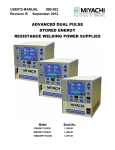
USER’S MANUAL REVISION B 990-137 May 2008 LIGHT FORCE WELD HEADS SERIES 50M Model Number Stock Number 50MF 50MFUB 2-50MF-000 2-50MFUB-000 Copyrighted © 2002, Miyachi Unitek Corporation The engineering designs, drawings and data contained herein are the proprietary work of MIYACHI UNITEK CORPORATION and may not be reproduced, copied, exhibited or otherwise used without the written authorization of MIYACHI UNITEK CORPORATION. Printed in the United States of America Revision Record Revision EO Date A 19161 01/02 B 21776 5/08 Basis of Revision New Release. Update to Miyachi Unitek logo, and added new CAUTION information. LIGHT FORCE WELD HEAD SERIES 50M ii 990-137 FOREWORD Thank you for purchasing a Miyachi Unitek™ Light Force Weld Head Series 50M. Upon receipt of your equipment, please thoroughly inspect it for shipping damage prior to its installation. Should there be any damage, please immediately contact the shipping company to file a claim, and notify Miyachi Unitek Corporation at: 1820 South Myrtle Avenue P.O. Box 5033 Monrovia, CA 91017-7133 Telephone: (626) 303-5676 FAX: (626) 358-8048 e-mail: [email protected] The purpose of this manual is to supply operating and maintenance personnel with the information needed to properly and safely operate and maintain the Light Force Weld Head. We have made every effort to ensure that the information in this manual is accurate and adequate. Should questions arise, or if you have suggestions for improvement of this manual, please contact us at the above location/numbers. Miyachi Unitek Corporation is not responsible for any loss due to improper use of this product. LIGHT FORCE WELD HEAD SERIES 50M 990-137 iii SAFETY NOTES This instruction manual describes how to operate, maintain and service the Light Force Weld Head Series 50M, and provides instructions relating to its SAFE use. Procedures described in this manual MUST be performed, as detailed, by QUALIFIED and TRAINED personnel. For SAFETY, and to effectively take advantage of the full capabilities of the tester, please read these instruction manuals before attempting to use the workstation. Procedures other than those described in this manual or not performed as prescribed in it, may expose personnel to electrical hazards. After reading this manual, retain it for future reference when any questions arise regarding the proper and SAFE operation of the tester. Please note the following conventions used in this manual: WARNING: Comments marked this way warn the reader of actions which, if not followed, might result in immediate death or serious injury. CAUTION: Comments marked this way warn the reader of actions which, if not followed, might result in either damage to the equipment, or injury to the individual if subject to long-term exposure to the indicated hazard. LIGHT FORCE WELD HEAD SERIES 50M iv 990-137 CONTENTS Revision Record................................................................................................................................. ii Foreword .................................................................................................................................... iii Safety Notes .................................................................................................................................... iv CHAPTER 1: DESCRIPTION....................................................................................................... 1-1 Section I: Features ................................................................................................................... Section II: Model Descriptions................................................................................................. Foot Actuated Series 50M Heads .......................................................................................... Model 50MF, Light Force Weld Head ............................................................................ Model 50MFUB, Light Force Weld Head with Parallel Gap Adjustment ...................... Section III: Major Components.................................................................................................. Section IV: Accessories ............................................................................................................. 1-1 1-2 1-2 1-3 1-3 1-4 1-5 CHAPTER 2: GETTING STARTED ............................................................................................ 2-1 Section I: Planning for Installation.......................................................................................... Section II: Installation of Electrode Holders and Tips ............................................................. Unitip Electrode Installation, Model 50MF........................................................................... Unibond Electrode Installation, Model 50MFUB ................................................................. Section III: Optic Pod (Microscope) Installation....................................................................... Section IV: Power Supply Connections ..................................................................................... Connection to Power Source.................................................................................................. Microwave Circuit Precautions.............................................................................................. 2-1 2-1 2-1 2-2 2-3 2-4 2-4 2-5 CHAPTER 3: OPERATION .......................................................................................................... 3-1 Parallel Gap Welding Variables............................................................................................. Electrode Materials .......................................................................................................... Area of Electrode Face..................................................................................................... Gap................................................................................................................................... Welding Force.................................................................................................................. Pulse Duration.................................................................................................................. Procedure ............................................................................................................................... 3-1 3-1 3-1 3-1 3-1 3-1 3-2 LIGHT FORCE WELD HEAD SERIES 50M 990-137 v CHAPTER 4: USER MAINTENANCE ........................................................................................ 4-1 Section I: Precautions................................................................................................................. Section II: Maintenance Procedures ............................................................................................ Unitip and Unibond Electrode Dressing ................................................................................ Unitip and Unibond Electrode Cleaning................................................................................ 4-1 4-1 4-1 4-2 CHAPTER 5: REPAIR SERVICE................................................................................................. 5-1 Service Repair at Plant........................................................................................................... 5-1 APPENDIX A: TECHNICAL SPECIFICATIONS .................................................................... A-1 Weld head Dimensions .......................................................................................................... A-2 APPENDIX B: ELECTRODE/THERMODE HOLDER CONVERSIONS ............................. B-1 Unitip to Unibond Electrode or Thermode Holder Conversion............................................. B-2 Unibond to Unitip Conversion............................................................................................... B-3 Index.................................................................................................................................................. Index-1 LIGHT FORCE WELD HEAD SERIES 50M vi 990-137 ILLUSTRATIONS Figure 1-1 1-2 Title Page 1-2 1-4 Model 50MF Light Force Weld Head (Typical)........................................................ Close-up of the Model HE50 Unitip Electrode Holder with Model UTM 112C Unitip Electrode .................................................................... Close-up of the Model HE50UB Unibond Electrode Holder with Unibond Electrodes.............................................................................................. 50M Series Weld Head Components......................................................................... 2-1 2-2 2-3 2-4 2-5 2-6 HE50 Unitip Electrode Holder with Unitip installed................................................. HE50UB Electrode Holder, Bottom View................................................................. HE50UB Electrode with EU1000 Unibond Electrodes ............................................. Installation of the Optic Assembly ............................................................................ Welding Cable/Transformer Power Connections ...................................................... External Filter for Elimination of Transient Voltage Problems................................. 2-1 2-2 2-3 2-3 2-4 2-5 3-1 Actual Force Versus Force Setting ............................................................................ 3-2 4-1 Unitip Dressing Procedure......................................................................................... 4-1 A-1 A-2 Light Force Weld Head, Side View........................................................................... A-2 Light Force Weld Head, Front View ......................................................................... A-3 B-1 B-2 Unitip to Unibond Electrode...................................................................................... B-2 Unibond to Unitip Conversion................................................................................... B-3 1-3 1-3 1-3 1-4 TABLES Table Title Page 1-1 1-2 1-3 Series 50MF Models .................................................................................................. 1-2 Accessories ................................................................................................................ 1-5 Electrodes and Thermodes......................................................................................... 1-6 2-1 Maximum Unitip Operational Force Limits .............................................................. 2-2 B-1 Conversion Kits ......................................................................................................... B-1 LIGHT FORCE WELD HEAD SERIES 50M 990-137 vii CHAPTER 1 DESCRIPTION Section I: Features The Unitek Peco Series 50 are precision, low inertia, heads designed for a wide variety of delicate, parallel gap welding and reflow soldering applications. True vertical electrode motion, a Series 50 feature, eliminates electrode wiping action at all welding levels and may increase electrode life. Targeting the work piece is made easier with true vertical motion. The 1.91 cm (¾ inch) vertical stroke permits easy access into deep packages. A low mass spring and compound lever force system ensures accurate, repeatable welding force in the 0.39/1.23 to 9.807 N (40/125 to 1000 gram force (gf)) range. The mechanism is designed so that the work pieces and electrodes will not be subjected to forces in excess of the Preset Force. Excessive welding force is a major cause of bond failure or inconsistent bonds, and short electrode life. The Series 50 Heads are available in four different electrode configurations. Each configuration can be foot pedal or air actuated. The Baseplate and Optic Mounting Assembly provide a stable work place and impose little restriction on the size of the work piece. Machined mounting surfaces on the left hand side and top of the Head allow them to be easily incorporated into a custom machine or work station. A selection of electrodes and thermodes allows welding or reflow soldering on devices such as semiconductor, thick film ceramic substrates, or printed circuit boards. See Appendix B for complete information on electrode/thermode conversions. The Welding Force is set by turning the knob located on the front of the weld head. A Force Curve, located on the right-hand side of the cover, converts the digital counter readings to gf. Calibration is set at the factory and does not change with time. All Series 50 Heads are supplied with a Baseplate, Optic Mounting Assembly, Model CP Cable Pedal, Voltage Sensing/Thermocouple Sensing Cable, and #2 AWG Welding cables. Optional Work Holders and Optic Accessories are available. LIGHT FORCE WELD HEAD SERIES 50M 990-137 1-1 CHAPTER 1: DESCRIPTION Section II: Model Descriptions Foot Actuated Series 50M Heads Foot actuation allows the operator to control the rate of electrode descent. Targeting of micro or subminiature work pieces is generally easier using foot actuation. Four different electrode configurations, each designed for different welding or reflow soldering applications comprise the Series 50M Foot Actuated Heads (figure 1-1). Table 1-1 lists the features of each model. Figure 1-1. Model 50MF Light Force Weld Head (Typical) Table 1-1. Series 50MF Models Model 50MF 50MFUB Stock Number 2-50MF-XXX 2-50MFUB-XXX Electrode Holder HE50 HE50UB Electrode Type Unitip® Unibond® Application Welding Welding NOTE: The “XXX” in the Stock number is the design sequence. LIGHT FORCE WELD HEAD SERIES 50M 1-2 990-137 CHAPTER 1: DESCRIPTION Model 50MF, Light Force Weld Head Model 50MF, Stock Number 2-50MF-XXX, uses only Unitip electrodes for micro-welding. Applications include welding gold or copper ribbon as thin as 0.0008 cm (0.0003 inch) to make interconnections in microwave and hybrid packages, and welding sub-miniature components such as beam lead diodes to flexible printed circuit boards and ceramic substrates. Welding Force is adjustable from 0.039 to 1.23 N (40 to 1000 gf). The Model 50MF is used with a power supply. Voltage sensing wires, connected to the HE50 Electrode Holder, provide the feedback required by the power supply. Model HE50 Electrode Holder, Stock Number 12-077XX, (figure 1-2) standard on the Model 50MF, is a low inertia, compliant electrode holder which ensures that the Unitip electrode will maintain the Preset Force on the work piece as it deforms during the welding process. The HE50 compliance feature functions in the Preset Force range from 0.039 to 1.23 N (40 to 125 gf). Figure 1-2. Close-up of the Model HE50 Unitip Electrode Holder with Model UTM 112C Unitip Electrode Model 50MFUB, Light Force Weld Head with Parallel Gap Adjustment Model 50MFUB, Stock Number 2-50MFUB-XXX, uses parallel gap Unibond electrodes. Applications include fine wire or ribbon bonding and tacking of hybrid lids to their packages in preparation for seam sealing. Welding Force is adjustable from 1.23 to 9.807 N (125 to 1000 gf). Model HE50UB Unibond Electrode Holder (figure 1-3), Stock Number 12-078-XX, standard on the 50MFUB, features flexures which allow the Unibond electrodes to conform to uneven work surfaces. The Electrode Gap Adjustment Knob feature permits a 0.10 cm (0.040 inch) maximum electrode gap spacing. Figure 1-3. Close-up of the Model HE50UB Unibond Electrode Holder with Unibond Electrodes LIGHT FORCE WELD HEAD SERIES 50M 990-137 1-3 CHAPTER 1: DESCRIPTION Section III. Major Components Figure 1-4 identifies the major components of the Light Force Weld Head. Vertical mounting post Optic mounting block assembly Locking handle Locking handle Optic mounting post Spacer Locking handle Head Collar Electrode holder Electrode Baseplate Figure 1-4. 50M Series Weld Head Components LIGHT FORCE WELD HEAD SERIES 50M 1-4 990-137 CHAPTER 1: DESCRIPTION Section IV: Accessories Table 1-2 lists the Accessories available for the Light force Weld Head Series 50M. Table 1-3 lists the electrodes that are available. Table 1-2. Accessories MODEL DESCRIPTION SMZ-660 Nikon, Stereo-Zoom 0.5X objective lens, 10X eyepieces, 195mm max. working distance. DFS Dual Firing Switch Junction Box. Connects two firing switch cables from two different heads to a single power source. DHD Device Holder for 0.3 to 0.8 to 1.5 cm (0.6 inch) wide Sidebraze Packages and 0.64 cm (0.250 inch) wide Cerdip/Plastic Packages with lengths up to 5.258 cm (2.070 inch). Has a spring loaded base. DHF Device Holder for Flat Substrates or Packages that are 5.258 cm to (5.08 0.250 to 2 inches) square. Has a spring loaded base. DHL Device Holder for Lead Frames that have 8 to 40 leads and are up to 10 inches long. HE50 Replacement Unitip Electrode Holder. Converts Series 50UB, 50RF, or 50LRF to accept Unitip Electrodes. Power straps included. HE50UB Replacement Unibond Electrode Holder. Converts Series 50, 50RF, or 50LRF to accept Unibond Electrodes. Power straps included. UTA Adapts HE50UB Unibond electrode holders for use with Unitip electrodes. PD Polishing Disks. Package of 50. (Not recommended for Unitips.) CPD Ceramic Polishing Disks for Unitip electrodes. Package of 20. WP Work Positioner, 7.6 cm (3 inch) diameter. Height adjustable from 3.65 to 5.08 cm (1-7/16 to 2 inches). LIGHT FORCE WELD HEAD SERIES 50M 990-137 1-5 CHAPTER 1: DESCRIPTION Table 1-3. Electrodes MODEL DESCRIPTION EU1000 RWMA 2 Unibond Electrode, 28.6 mm (1⅛-inch) long with 0.508 mm x 0.762 mm (0.020 x 0.030 inch) deep face. EU1002 RWMA 2 Unibond Electrode, 50.8 mm (2 inch) long with 0.508 mm x 0.762 mm (0.020 x 0.030 inch) deep face. EU2030M Unibond Electrode, Molybdenum, Copper-Clad Shank, 28.6 mm (1⅛-inch) long with 0.508 mm x 0.762 mm (0.020 x 0.030 inch) deep face. EU2030ML Unibond Electrode, Molybdenum, Copper-Clad Shank, 50.8 mm (2 inch) long with 0.508 mm x 0.762 mm (0.020 x 0.030 inch) deep face. UTM111C Unitip Electrode, Molybdenum, 0.229 mm W x 0.254 mm D (0.009 inch W x 0.010 inch D) with 0.025 mm (0.001 inch) gap. UTM112C Unitip Electrode, Molybdenum, 0.254 mm W x 0.254 mm D (0.010 inch W x 0.010 inch D) with 0.051 mm (0.002 inch) gap. UTM222C Unitip Electrode, Molybdenum, 0.457 mm W x 0.508 mm D (0.018 inch W x 0.020 inch D) with 0.051 mm (0.002 inch) gap. UTM224C Unitip Electrode, Molybdenum, 0.508 mm W x 0.508 mm D (0.020 inch W x 0.020 inch D) with 0.010mm (0.004 inch) gap. UTM111L Unitip Electrode, Molybdenum, 0.229 mm W x 0.254 mm D (0.009 inch W x 0.010 inch D) with 0.025 mm (0.001 inch) gap. UTM112L Unitip Electrode, Molybdenum, 0.254 mm W x 0.254 mm D (0.010 inch W x 0.010 inch D) with 0.051 mm (0.002 inch) gap. UTM152L Unitip Electrode, Molybdenum, 0.254 mm W x 0.127 mm D (0.010 inch W x 0.005 inch D) with 0.051 mm (0.002 inch) gap. UTM222L Unitip Electrode, Molybdenum, 0.457 mm W x 0.508 mm D (0.018 inch W x 0.020 inch D) with 0.051 mm (0.002 inch) gap. UTM224L Unitip Electrode, Molybdenum, 0.508 mm W x 0.508 mm D (0.020 inch W x 0.020 inch D) with 0.010 mm (0.004 inch) gap. UTM237L Unitip Electrode, Molybdenum, 0.508 mm W x 0.762 mm D (0.020 inch W x 0.030 inch D) with 0.018 mm (0.007 inch) gap. LIGHT FORCE WELD HEAD SERIES 50M 1-6 990-137 CHAPTER 2 GETTING STARTED Section I: Planning for Installation The outline dimensions of the weld head are contained in Appendix A, Technical Specifications. Section II: Installation of Electrode Holder and Tip CAUTION Do not modify the electrode holders or attach additional mechanisms to the moving parts of the head. Doing so may hurt welding performance, damage the head, and void the warranty. Unitip Electrode Installation, Model 50MF 1 Open the electrode holder by loosening the Electrode Clamping Screw. 2 Hold the left half of the Electrode Holder open using the left hand. Using the right hand, insert the Unitip into the Electrode Holder. Each half of the Electrode Holder has been machined with concave grooves to accept 3 mm (0.125 inch) diameter electrodes. 3 Gently squeeze the Electrode Holder closed and then rotate the Unitip so that the vertical line formed on the tip by the insulation layer lies exactly between the two Electrode Holder halves when viewed from the front of the head. 4 Verify that the upper end of the Unitip is seated against the top of the machined groove in the Electrode Holder. Wiggle the left half of the Electrode Holder to ensure that it fits against the Unitip and then finger tighten the Electrode Clamping Screw. CAUTION: Do not over-tighten the clamping screw. Figure 2-1. HE50 Unitip Electrode Holder with Unitip Installed Unitip electrode faces can be severely damaged by applying excessive bonding forces. Table 2-1 gives maximum operational force limits in kilograms of force. See Chapter 4 for Unitip cleaning and dressing instructions. LIGHT FORCE WELD HEAD SERIES 50M 990-137 2-1 CHAPTER 2: GETTING STARTED Table 2-1 Maximum Unitip Operational Force Limits UNITIP P/N MAX FORCE (kgf) UTM111L UTM112L UTM152L UTM222L UTM111C UTM112C UTM222C UTM224C UTM237L 0.94 0.94 0.47 3.75 0.94 0.94 3.75 3.75 4.57 Unibond Electrode Installation, Model 50MFUB 1 Check the voltage sensor cable located on the underside of the HE50UB Electrode Holder. Verify that the two slotted head screws attaching the voltage sensing cable to the flexure assemblies, shown in figure 2-2, are securely tightened. Erratic operation results if they are loose. Testing One Electrode gap adjustment knob Sensing cable Electrode mount alignment screw (one each side) Sensing cable screws Electrode holder clamp screws Figure 2-2. HE50UB Electrode Holder, Bottom View NOTE: The Unitek Peco closed-loop power supplies are the only controls that uses remote voltage sensing. 2 Loosen the Electrode Holder Clamp Screws. Set the Electrode Gap Adjustment Knob for maximum gap width and insert the Unibond Electrodes into the holders as shown in figure 2-3. 3 Loosely hold the tips or electrodes in place and rotate the Electrode Gap Adjustment Knob to its fully clockwise (closed) position. LIGHT FORCE WELD HEAD SERIES 50M 2-2 990-137 CHAPTER 2: GETTING STARTED 4 Orient the electrodes so they contact each other along their entire length and are perpendicular to the working surface. Position the electrodes vertically in the holder so the tip ends coincide. 5 Tighten the Electrode Holder Clamp Screws. Flexures CAUTION: Do not over-torque the Clamp Screws. Doing so will deform the Flexure, dramatically reducing its life. 6 Unibond electrodes Figure 2-3. HE50UB Electrode with EU1000 Unibond Electrodes Open the electrodes to the desired operating gap by turning the Electrode Gap Adjustment Knob counterclockwise. NOTE: The operating gap can be safely opened to a maximum of 1.0 mm (0.040 inches). Section III. Optic Pod (Microscope) Installation Set screw Place the Optic Pod (figure 2-4) into the Optic Mounting Post and secure it with the Mounting Set Screw. Assemble the Optic Pod in accordance with instructions that came with the Assembly. Optic mounting post Figure 2-4. Installation of the Optic Assembly LIGHT FORCE WELD HEAD SERIES 50M 990-137 2-3 CHAPTER 2: GETTING STARTED Section IV: Power Supply Connections Connection to Power Source 1 2 Reference figure 2-5. Place one end of each #2 welding cable over the threaded stud found at the lower back of the head. Using the hardware supplied in the Shipping Kit, secure each cable with a flat washer and lock nut. Head Power supply or transformer Threaded stud Lock nut Flat washer #2 welding cable (2) Connect the terminal at the Flat washer other end of each welding Screw cable to the power supply or transformer, using the screw, flat washer, and Lock nut lock nut supplied with that unit, as shown. Ensure that the washers are placed Figure 2-5. Welding Cable / Transformer Power Connections under the screw heads, not between the bus bars and terminals. Tighten all of the connections. NOTE: Do not cross cables when connecting the weld head to a power supply. This will cause the power supply Overload Light to come on, preventing weld current from occurring. 3 If the power supply has closed-loop feedback, connect the Voltage Sensing Cable on the 50MF and the 50MFUB, the power supply as illustrated in the power supply manual. 4 Connect the Weld Head Firing Switch Cable to the matching Firing Switch Cable coming from the power supply. For the Model 125 Power Supply, the Firing Switch Receptacle is located on the front panel. LIGHT FORCE WELD HEAD SERIES 50M 2-4 990-137 CHAPTER 2: GETTING STARTED Microwave Circuit Precautions Some hybrid microwave component manufactures have experienced a transient voltage problem during welding which can damage Field Effect Transistors (FETs). This problem is caused by voltage leakage through the primary to secondary capacitance of the Welding Transformer in combination with a low package to ground capacitance. Figure 2-6 shows the External Filter Network required to shunt the transient voltage through a very low impedance path to ground, thus protecting the FET device. Figure 2-6. External Filter for Elimination of Transient Voltage Problem LIGHT FORCE WELD HEAD SERIES 50M 990-137 2-5 CHAPTER 3 OPERATION Parallel Gap Welding Variables Electrode Materials Use RWMA 2 copper electrodes for resistive and/or hard materials such as gold plated Kovar and nichrome. Use molybdenum or tungsten electrodes for conductive or soft materials such as copper and gold. Unibond Electrodes are available in both RWMA-2 copper and RWMA-14 molybdenum. Unitip Electrodes are only available in molybdenum. Testing has shown that Unitip Electrodes with a face size of 0.457 mm (0.018 inches) wide by 0.508 mm (0.020 inches) deep or larger can be used to weld gold plated kovar ribbon that is 0.051 mm (0.002 inches) thick or less without experiencing electrode sticking to the gold plated kovar ribbon. Testing has also shown that Unitip Electrodes UTM111C, UTM111L, UTM112C, and UTM112L can not be used to weld gold plated kovar ribbon because these tips sizes experience severe electrode sticking, regardless of weld energy settings or gold plated kovar ribbon thickness. See Chapter 1, Section IV for a complete listing of Unibond and Unitip electrodes. Area of Electrode Face For a given Welding Force, a large electrode face puts less pressure on the workpieces and produces a larger welding area. A larger electrode face also requires more energy, provided the contact resistance between the electrode face and work piece does not change drastically. Insufficient pressure on the workpieces is likely to cause spitting of the work piece material or electrode sticking. When welding conductive materials, use electrodes with the smallest face possible. Gap The larger the distance between the electrodes, the greater the energy required to make a given weld. Unitip Electrodes come in a variety of fixed gap sizes ranging from 0.0025 to 0.018 cm (0.001 to 0.007 inch) with 0.0025, 0.0050, and 0.0102 cm (0.001, 0.002, and 0.004 inches) being the most popular gap sizes. As a starting point, select a gap size that approximately matches the thickness of the work piece material. Welding Force Increasing the Welding Force lowers the contact resistance between the workpieces and between the workpieces and the electrodes, requiring more energy to make a given weld. Pulse Duration The longer the Pulse Duration, the greater the penetration of the weld into both top and bottom workpieces and the greater the effect of the heat upon the metallurgical structure of the workpieces. In general, use pulse durations less than 15 ms for welding and durations greater than 20 ms for brazing or reflow soldering. To maximize electrode life, use Unibond Electrodes for brazing. Pulse Duration is critical when welding conductive materials such as copper and gold and should be kept to a minimum. LIGHT FORCE WELD HEAD SERIES 50M 990-137 3-1 CHAPTER 3: OPERATION Procedure Use the force curve label displayed on the side of the weld head as shown in figure 3-1 to set the welding force. The vertical axis represents the actual welding force. The horizontal axis represents the corresponding force setting required to produce the actual force. Use the appropriate curve as follows: Top curve Bottom curve 50MFUB 50MF Refer to the Instruction Manual which accompanies Power Supply or Time-At-Temperature Controller to supplement these instructions. Figure 3-1. Actual Force Versus Force Setting LIGHT FORCE WELD HEAD SERIES 50M 3-2 990-137 CHAPTER 4 USER MAINTENANCE Section I: Precautions WARNING: Do not remove the spring housing cover for any reason. This cover protects the user should the force spring break during operation. The force spring does not require maintenance nor is it accessed during calibration. CAUTION: All bearing surfaces are designed for non-lubricated operation. Do not oil any bearings. Guide bearings are factory pre-loaded and therefore do not require adjustment. All vertical motion bearings are installed at the factory and are sealed with a locking compound. If the seal is broken, the warranty on the bearings will be void. Section II: Maintenance Procedures Unitek Peco Heads are designed to minimize routine maintenance. Daily maintenance should be limited to electrode dressing and cleaning. Unitip and Unibond Electrode Dressing New Unitip and Unibond electrodes must be dressed to ensure that the electrode face is parallel to the work piece surface. The small Unitip and Unibond tip geometry makes the electrode face extremely susceptible to damage during dressing or cleaning. Dress Unibond electrodes with a Model PD Polishing Disk, which is made from #600 grit emery paper. Dress Unitip electrodes with a Model CPD Ceramic Polishing Disk. Do not use the PD (#600 grit) on Unitip. NOTE: Thermodes do not require dressing. Install Unitip or Unibond electrode. Adjust the Work Holder surface height so that it is at the same level as the work piece surface. Place a Model CPD polishing disk or CPD ceramic polishing disk on the Work Holder surface, directly beneath the electrode face. Figure 4-1 shows a Unitip electrode being correctly and incorrectly dressed. Bring the electrode face into contact with the polishing disk. Avoid applying a force of more than 150 grams to smallest Unitip electrode tips. Gently pull the polishing disk forward, keeping the direction of pull parallel to the electrode gap. CORRECT INCORRECT Figure 4-1. Unitip Dressing Procedure LIGHT FORCE WELD HEAD SERIES 50M 990-137 4-1 CHAPTER 4: USER MAINTENANCE NOTE: Do not rock the polishing disk from side to side or front to back. Clean the electrode face with a small lint free swab saturated in alcohol to remove any residue created by the dressing procedure. Low pressure compressed air can also be used to remove any residues. Examine the electrode face with a small mirror for flatness and direction of surface scratches. A properly dressed electrode will have small scratch marks that are parallel to the electrode gap. Unitip and Unibond Electrode Cleaning Depending on use, periodically resurface Unitip and Unibond electrodes using the techniques described above to remove oxides and welding debris from the electrodes. These oxides are a natural result of the bonding process. When welding with Unitip electrodes, a small puff of smoke appears as each bond is made. The absence of this puff of smoke is a clear signal to the operator that it is time to clean the electrode face. Use organic solvents to clean flux and other buildup from Thermode tips. LIGHT FORCE WELD HEAD SERIES 50M 4-2 990-137 CHAPTER 5 REPAIR SERVICE Service Repair at Plant Unitek Miyachi provides a quick turn-around repair service for both warranty and non-warranty repairs. Call the Customer Service Department at the telephone number shown in the Foreword of this manual. Please include information concerning the type of problem which you are experiencing. Include with the shipping information the name and telephone number of the person whom we should call with the estimated cost of repairs. LIGHT FORCE WELD HEAD SERIES 50M 990-137 5-1 APPENDIX A TECHNICAL SPECIFICATIONS LIGHT FORCE WELD HEAD SERIES 50M 990-137 A-1 A-2 12.70 (0.50) 406.40 (16.00) 422.91 (16.65) 406.40 (16.00) Model 50MFUB 229.36 (9.03) 61.98 (2.44) Max user space 19.05 (0.75) Total travel 244.35 (9.62) Max 120.65 (4.75) Ref 172.97 (6.81) ¼-20 UNC 2 holes (farside) standard mounting position 45.97 (1.81) 35.56 (1.40) 35.56 (1.40) 268.22 (10.56) ¼-20 UNC 2 holes optional mounting position 610.00 (24.00) Ref 38.1 (1.50) 139.70 (5.50) 41.25 (1.624) Diameter Model 50MF 118.36 (4.66) 48.67 Dashed outline represents (2.31) optional air actuated assembly Keps nut Flat washer 41.25 (1.624) Diameter 80.26 (3.16) 69.85 (2.75) 5.62 (142.75) Ref setting APPENDIX A: TECHNICAL SPECIFICATIONS Weld Head Dimensions Dimensions in millimeters (inches) Figure A-1. Light Force Weld Head, Side View LIGHT FORCE WELD HEAD SERIES 50M 990-137 APPENDIX A: TECHNICAL SPECIFICATIONS Optic mounting post 63.50 (2.50) 91.44 (3.60) 112.78 (4.44) Spacer 120.65 (4.75) Collar 47.75 (1.88) 63.50 (2.50) 68.33 (2.69) REF 254.00 (10.00) Figure A-2. Light Force Weld Head, Front View LIGHT FORCE WELD HEAD SERIES 50M 990-137 A-3 APPENDIX B ELECTRODE HOLDER CONVERSIONS A conversion kit contains all of the necessary parts to convert Model 50MF to Model 50MFUB. In addition, a UTA Unitip Adapter is available to convert a Unibond electrode holder for use with Unitip electrodes. Table B-1 lists the Conversion Kits. Table B-1. Conversion Kits Function Convert 50MF to 50MFUB. Part No. 12-078-01 Convert Unibond electrode holder for use with Unitip electrodes 12-048-02 (UTA) Contents Electrode Flexure Assy, 4-31966-01; Ship Kit, 4-80940-01, containing: Block Assy Adapter, 4-31948-01; Electrode Sleeve, 4-30365-01; 2 (each) #8 flat washers, #8 lock washers, 8-32x1/4 socket button cap screws, assorted socket wrenches. Set of two adapters. LIGHT FORCE WELD HEAD SERIES 50M 990-137 B-1 APPENDIX B: ELECTRODE HOLDER CONVERSION Unitip to Unibond Electrode or Thermode Holder Conversion Reference figure B-1. Perform the following steps: 1 Remove both flexures from the weld head, by removing the two M4 socket head button cap screws, lock washers and flat washers. 2 Remove the four 4-40 socket head cap screws that hold the electrode holder, to the head. Carefully remove the electrode holder by lowering it straight down. Retain the screws. 3 From the Adapter Kit, obtain the Electrode Sleeve and Adapter Block Assembly and slip the sleeve over the shaft on the adapter block. 4-40 socket head cap screws Electrode holder M4 socket head button cap screws Flexures Figure B-1. Unitip to Unibond Electrode 4 Position the assembled sleeve and adapter block under the slide shaft and rotate the sleeve so that the split in the sleeve is toward the back of the weld head. Attach the assembly to the weld head with the four 4-40 socket head cap screws removed in step 2. 5 Slide the Unibond electrode holder (Electrode Flexure Assembly) or thermode holder (Thermode-Unitip Holder Assembly) over the insulator. Align both halves so that they are parallel to each other on a horizontal plane and lock them into position by tightening the M4 socket cap screws on each side of the electrode holder. Alternate the tightening process from side to side. Verify that the electrode holder halves are not shorted together at the back of the holder and that they are still parallel. 6 Connect both flexures to the weld head using the two M4 socket head button cap screws, lock washers and flat washers in the Ship Kit. LIGHT FORCE WELD HEAD SERIES 50M B-2 990-137 APPENDIX B: ELECTRODE HOLDER CONVERSION Unibond to Unitip Conversion Reference figure B-2. Perform the following steps: 1 2 Slide the set of Adapters into the slot in the Unibond holder. The Adapters may be slid in either from the top or bottom, whichever is most convenient. Slide the Unitip into the holder between the adapter set halves, and secure them by tightening the socket head cap screws in the front of the holder. Unitip Adapter set Unibond holder Socket head cap screws Figure B-2. Unibond to Unitip Conversion LIGHT FORCE WELD HEAD SERIES 50M 990-137 B-3 INDEX -AAccessories, Table of ......................... 1-5 Area of electrode face ........................ 3-1 -CCaution, Definition of ........................ Cleaning electrodes............................ Components, Weld head .................... Connecting power supply .................. Conversion Kits, Table ...................... Conversions Electrode holder ............................ Unibond to Unitip ......................... Unitip to Unibond Electrode ......... -EElectrode cleaning.............................. Electrode dressing.............................. Electrode face area............................. Electrode holder conversion .............. Electrode holders, Unibond,installation...................... Unitip,installation.......................... Electrode materials ............................ Electrode tips, Unibond,installation...................... Unitip,installation.......................... Electrode Holder Conversion............. Electrodes, Table of ........................... -F- 1-2 1-2 1-2 3-1 iii iv 4-2 1-4 2-4 B-1 -GGap..................................................... 3-1 Getting started.................................... 2-1 B-2 B-3 B-2 How to reach us ................................. iii -DDefinitions: Caution .......................................... Warning......................................... Description of Series 50 Light Force Weld Head................. Dressing electrodes ............................ Duration of pulse ............................... 50MF models, Table .......................... 50MF Series description .................... Foot actuated Models (50MF Series), Description .................................... Force, welding ................................... Foreword ............................................ iv iv 1-1 4-1 3-1 4-2 4-1 3-1 B-2 2-2 2-1 3-1 2-2 2-1 B-2 1-6 -H- -IInstallation, Optics assembly ............................ Planning ........................................ Unibond electrode holders and tips Unitip electrode holders and tips .. 2-3 2-1 2-1 2-1 -MMajor components ............................. 1-4 Microwave circuit precautions........... 2-5 Model 50MF Light Force Weld Head, Description .................................... 1-2 Model 50MFUB Light Force Weld Head with parallel gap adjustment, Description .................................... 1-3 -OOperating procedure .......................... Operation ........................................... Optics assembly installation .............. Outline drawings................................ 3-1 3-1 2-3 A-2, A-3 -PParallel gap welding variables ........... 3-1 Area of electrode face ................... 3-1 LIGHT FORCE WELD HEAD SERIES 50M 990-137 INDEX-1 INDEX Duration of pulse........................... Electrode face area ........................ Electrode materials........................ Force, welding............................... Gap ................................................ Pulse duration................................ Welding force................................ Planning for installation..................... Power supply connections ................. Precautions with microwave circuitry Precautions, User maintenance .......... Procedures, User maintenance ........... Pulse duration .................................... 3-1 3-1 3-1 3-1 3-1 3-1 3-1 2-1 2-4 2-5 4-1 4-1 3-1 -RRecord of revisions ............................ ii Repair Service.................................... 5-1 Revision record .................................. ii Electrode holder ............................ Electrode holders, Installation ...... Electrodes installation ................... Conversion holder to: Unibond electrode or thermode User maintenance Electrode Cleaning .................................... Dressing .................................... Precautions, ................................... Procedures ..................................... 1-3 2-2 2-2 B-2 4-2 4-1 4-1 4-1 -WWarning, Definition of....................... iv Weld head major components............ 1-4 Welding force..................................... 3-1 Welding, Parallel gap variables (See parallel gap welding) -SSafety Notes ....................................... iv Specifications..................................... A-1 -TTables Accessories.................................... Conversion Kits............................. Electrodes...................................... 50MF Models ................................ Thermode holders ......................... 1-5 B-1 1-6 1-2 1-5 -UUnibond Converting electrode for Unitip .... B-2 Electrode holder ............................ 1-3 -U- (continued) Electrode holders, installation....... 2-2 Electrodes installation ................... 2-2 Unitip LIGHT FORCE WELD HEAD SERIES 50M INDEX-2 990-137