1
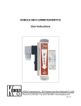
KOBOLD LPS AIR FLOW MONITOR
User Instructions
Kobold Instruments Inc.
1801 Parkway View Drive
Pittsburgh, PA 15205
412-788-2830 Fax 412-788-4890
KOBOLD Instruments Canada Inc.
9A Aviation
Point Claire, QC H9R 4Z2
514-428-8090 Fax 514-428-8899
www.koboldusa.com
FM Rev. 04/13
LPS
Table of Contents
1.0
General .............................................................................................
1
2.0
Specifications ...................................................................................
2
3.0
Installation instructions......................................................................
4
4.0
Operation ..........................................................................................
5
4.1
Adjusting the setpoint ..........................................................
5
4.1.1 Activating the Setpoint on Rising Flow ................
5
4.1.2 Activating the Setpoint on Falling Flow................
5
Adjustment of the Setpoint Beyond Factory Limits .........
5
4.2
5.0
Maintenance .....................................................................................
6
6.0
Arrival of Damaged Equipment ......................................................
6
7.0
Need Help With Your LPS ...............................................................
6
List of Diagrams
Diagram 2.2
Electrical Connections ...................................................
2
List of Tables
Table 2.1
Materials of Construction ...................................................... 2
FM Rev. 04/13
LPS
KOBOLD LPS AIR FLOW MONITOR
User Instructions
CAUTION:
1.0
For safety reasons, please read the cautionary information located at
the end of the manual, before attempting installation.
General
The KOBOLD LPS flow monitor is an air flow activated switch intended for use in
situations where a minimum or maximum airflow must be maintained. It is designed to
be mounted directly on duct work for use in applications where airtight installation is not
necessary.
The device operates as follows:
1. Flowing air impacts upon a paddle attached to a lever which has its pivot point
in the instrument housing (outside the airflow). This causes the paddle/lever
arrangement to pivot about its hinge point.
2. The motion of the paddle/lever is opposed by a spring whose tension is
setscrew adjustable. The amount that the lever pivots for a given airflow can,
in this fashion, be controlled.
3. Positioned in the path of the paddle/lever is a microswitch. When the lever
pivots through a preset angle, the microswitch is activated.
4. Result: Activation of the microswitch can, through use of the set screw/spring
arrangement, be chosen to occur at a predetermined airflow rate.
FM Rev. 04/13
LPS
2.0
2
Specifications
Operating Principle:
Spring-resisted paddle
Range:
195 - 1575 ft./min. (turn-off)
395 - 1810 ft./min. (turn-on)
Pressure:
Ambient
Maximum Temperature:
185° F
(Media & Ambient)
Table 2.1 Materials of Construction
Paddle:
SS
Lever:
Brass
Connection/Mounting Plate:
Steel
Housing:
Base: ABS
Cover: Polycarbonate
Diagram 2.2
Electrical Connections
Switching Voltage:
24 - 250 VAC
Switching Current:
8 A Max. (Inductive)
15 A Max. (Resistive)
Maximum Power:
2000 VA
Switch Action:
SPDT
Connections:
Red: Common
Blue: N/C (opens w/flow)
White: N/O (closes w/flow)
CAUTION: Exceeding any one maximum electrical rating will create a fire hazard.
FM Rev. 04/13
3
3.0
LPS
Installation Instructions
CAUTION:
For safety reasons, please read the cautionary information located at
the end of the manual, before attempting installation.
The LPS flow monitor is designed for direct installation onto the flat surfaces of air
handling duct work. The orientation of the instrument is unimportant. However, the
airflow direction must be in the direction indicated by the arrow on the instrument base.
The instrument is held in place by four (4) sheet metal screws (not supplied). For
installation, after selecting an appropriate mounting location with sufficient clearance for
both the paddle and cover housing, trace around the inside perimeter of the mounting
gasket with a pencil or marker. Mark the mounting screw holes and then drill
appropriately sized pilot holes for the mounting screws (self-drilling screws may also be
used). Neatly trim the marked opening in a workmanlike manner to allow for sufficient
paddle and lever clearance.
Note: To avoid damage in transit, your LPS flow switch has been disassembled. It
temporarily consists of three parts. These parts are: 1) main body, 2) gasket, 3)
paddle. The gasket is to be used during installation to form a vibration free seal
with the duct metal. The paddle must be reinstalled to the main body as follows:
1. Remove screw and lockwasher from lower part of paddle arm.
2. Align holes in paddle with screw hole and positioning pin in paddle arm.
3. Replace screw and lock washer.
4. To check your work, compare with LPS picture on cover of this manual.
5. Congratulations! You are now a veteran LPS paddle installer.
Use the supplied gasket to seal off the area between the LPS and the supply duct.
Install the assembled flow switch into the duct and secure the mounting screws.
Connect to the internal switch by removing housing, leading cable through inlet and
connecting according to Diagram 2.2.
FM Rev. 04/13
LPS
4.0
4
Operation
After installation, the switch point may be adjusted. Note that the switch point is
dependent upon the mounting orientation of the LPS. This is due to the weight of the
paddle acting with or against the paddle spring. If you have reoriented your LPS, it will
be necessary to reset the switch point.
4.1 Adjusting the Setpoint
Diagram 2.2 shows the placement of the setpoint adjustment screw. Turning this
screw clockwise will increase the flow rate required to activate the switch.
4.1.1 Activating the Setpoint on Rising Flow
To adjust the microswitch to trigger on rising flow, do as follows:
1. Establish desired setpoint flow rate in the system.
2. Turn setpoint screw fully clockwise.
3. Slowly turn setpoint screw counterclockwise until microswitch
activates
4. Replace housing cover.
4.1.2
Activating the Setpoint on Falling Flow
To adjust the microswitch to trigger on falling flow, do as follows:
1. Establish desired setpoint flow rate in the system.
2. Turn the setpoint screw fully counterclockwise.
3. Slowly turn setpoint screw clockwise until the microswitch
activates.
4. Replace housing cover.
4.2
Adjustment of the Setpoint Beyond Factory Limits
Since the LPS is activated by the force of the moving air, it is possible to increase the
maximum setpoint values by shortening the paddle. If you choose to do this, we
recommend that you trim the paddle a little at a time to avoid overcompensation.
FM Rev. 04/13
5
5.0
LPS
Maintenance
The simple design of the LPS assures an almost maintenance free instrument. The only
possible maintenance area is the lever hinge of the LPS. If operating in a humid
environment, we suggest that the lever hinge be checked occasionally to assure free
movement.
6.0
Arrival of Damaged Equipment
Your instrument was inspected prior to shipment and found to be defect-free. If damage
is visible on the unit, we advise that you carefully inspect the packing in which it was
delivered. If damage is visible, notify your local carrier at once, since the carrier is liable
for a replacement under these circumstances. If your claim is refused, please contact
KOBOLD Instruments for further advisement.
7.0
Need help with your LPS?
Call one of our friendly engineers at 412-788-2830.
FM Rev. 04/13
LPS
6
Caution
PLEASE READ THE FOLLOWING GENERAL FLOW METER/ MONITOR
WARNINGS BEFORE ATTEMPTING INSTALLATION OF YOUR NEW
DEVICE. FAILURE TO HEED THE INFORMATION HEREIN MAY
RESULT IN EQUIPMENT FAILURE AND POSSIBLE SUBSEQUENT
PERSONAL INJURY.
FM Rev. 04/13
7
LPS
•
User's Responsibility for Safety: KOBOLD manufactures a wide range of
process sensors and technologies. While each of these technologies are
designed to operate in a wide variety of applications, it is the user's
responsibility to select a technology that is appropriate for the application,
to install it per these installation instructions, to perform tests of the
installed system, and to maintain all components. The failure to do so could
result in property damage or serious injury.
•
Proper Installation and Handling: Use of sealant is advisable with most
installations to minimize air loss. Always check for leaks prior to system
start-up.
•
Wiring and Electrical: The electrical connection specifications for the LPS
are contained in Diagram 2.2. The sensor system should never exceed
these ratings. Electrical wiring of the sensor should be performed in
accordance with all applicable national, state, and local codes.
•
Temperature and Pressure: The LPS is designed for use in application
temperatures up to 185°F, and for use at ambient pressures. Operation
outside these limitations will cause damage to the unit and possible
personal injury.
•
Material Compatibility: The LPS is made of steel, brass and SS. The
housing is ABS plastic. Make sure that the unit is chemically compatible
with the application media. While the switch housing is liquid resistant
when installed properly, it is not designed to be immersed. It should be
mounted in such a way that it does not normally come into contact with
fluid.
•
Flammable, Explosive and Hazardous Applications: The LPS is not of
an explosion-proof design. The LPS models should not be used in areas
where an explosion-proof design is required.
•
Make a Fail-Safe System: Design a fail-safe system that accommodates
the possibility of switch or power failure as well as operator error. In critical
applications, KOBOLD recommends the use of redundant backup systems
and alarms in addition to the primary system.
FM Rev. 04/13