1
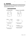
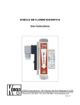
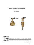
KOBOLD SV FLOWMETER/SWITCH
User Instructions
KOBOLD Instruments Inc. 1801 Parkway View Drive Pittsburgh PA 15205
Phone (412) 788-2830 • Fax (412)-788-4890 • www.koboldusa.com
R2_4-13
SV
Table Of Contents
KOBOLD SV FLOWMETER/SWITCH
1.0
General . . . . . . . . . . . . . . . . . . . . . . . . . . . . . . . . . . . . . . . . . . . . . 1
2.0
Specifications. . . . . . . . . . . . . . . . . . . . . . . . . . . . . . . . . . . . . . . . . . 1
3.0
Installation . . . . . . . . . . . . . . . . . . . . . . . . . . . . . . . . . . . . . . . . . . . 2
4.0
Electrical Installation . . . . . . . . . . . . . . . . . . . . . . . . . . . . . . . . . . . . 3
5.0
Operation . . . . . . . . . . . . . . . . . . . . . . . . . . . . . . . . . . . . . . . . . . . . 4
5.1
Reading Flow. . . . . . . . . . . . . . . . . . . . . . . . . . . . . . . . . . . . . . . . . . 4
5.2
Adjusting the Setpoint for Increasing Flow. . . . . . . . . . . . . . . . . . . . 4
5.3
Adjusting the Setpoint for Decreasing Flow. . . . . . . . . . . . . . . . . . . 4
6.0
Arrival of Damaged Equipment . . . . . . . . . . . . . . . . . . . . . . . . . . . . 5
7.0
Maintenance . . . . . . . . . . . . . . . . . . . . . . . . . . . . . . . . . . . . . . . . . . 5
8.0
Need help with your SV Flow Switch?. . . . . . . . . . . . . . . . . . . . . . . 5
List Of Diagrams
Diagram 4.1
Electrical Connections. . . . . . . . . . . . . . . . . . . . . . . . . . . . . . 3
List of Tables
Table 2.1
Material Composition. . . . . . . . . . . . . . . . . . . . . . . . . . . . . . . 2
FM Rev. 4/16/13
SV
KOBOLD SV FLOWMETER/SWITCH
User Instructions
CAUTION:
1.0
For safety reasons, please read the cautionary information located at
the end of the manual, before attempting installation.
General
The KOBOLD SV flowmeter/switch is intended for applications where only
measurement, or measurement and flow monitoring of liquids and gases with vertical,
upward flow is required. The instrument has a direct reading scale and may be factory
fitted with single or dual magnetic reed contacts that actuate when the desired flow is
achieved.
The principle of operation of the SV is that of the well-known float in a conical tube. The
KOBOLD SV, however, uses our patented cylindrical control tube with V-groove to
replace the conical tube. This method has advantages in that the float is stabilized over
its entire measuring range and offers a large flow range in a small instrument. The float
has a built-in permanent magnet that actuates a reed switch (when equipped) mounted
on the exterior housing of the device. The optional switch is therefore hermetically
separated from the medium. The optional switches are user adjustable so that setpoints
may be adjusted to any flow value within the range of the instrument.
2.0
Specifications
Measurement Accuracy:
Maximum Medium Temperature:
-with PP or PVDF Float
+/- 5% of Full Scale
240 Degrees F
160 Degrees F
Maximum Operating Pressure:
145 PSIG
Switch Specifications:
Maximum Voltage:
240 VAC
Maximum Current:
SPST (N/O): 1.5 A
SPDT: 0.8 A
Maximum Power Dissipation:
SPST (N/O): 50 VA/50 W
SPDT: 30 VA/30 W
Environmental Protection:
IP 65 (IEC 259)
(Equal to NEMA 4)
cCSAus Approval
FM Rev. 4/16/13
SV
2
Table 2.1
Material Composition
Housing:
Flow Tube:
Slotted Nozzle:
Float:
Fittings:
Seals:
3.0
Brass Version
SS Version
Anodized Aluminum
Borosilicate Glass
Ni-Plated Brass
Ni-Plated Brass or PP
Ni-Plated Brass
NBR
Anodized Aluminum
Borosilicate Glass
304 SS
304 SS or PVDF
304 SS
FKM
Installation
CAUTION:
For safety reasons, please read the cautionary information located at
the end of the manual, before attempting installation.
To install, proceed as follows:
1. The SV flowmeter/switch must be installed in a vertical position with the flow
inlet at the bottom.
2. The medium must not contain any solids or contaminants that could precipitate
out of solution and deposit on the instrument's inner walls. This would prevent
proper operation of the device. Unclean media should be filtered upstream of
the SV. KOBOLD offers a magnetic/screened filter suitable for such purposes
(type MFR).
3. Do not install meter on large masses of ferritic materials, or in areas where
strong electric fields are present, as this will hamper proper operation of the
reed contact.
FM Rev. 4/16/13
3
4.0
SV
Electrical Installation
Maximum values of current and voltage must not be exceeded on the reed relay. If
driving inductive or capacitive loads, we recommend the use of a suitable isolation relay,
KOBOLD provides a line of relays for such instances. If an isolation relay is not used, a
clamping diode is highly recommended for DC inductive loads to minimize contact
arcing, which will destroy the reed switch.
Diagram 4.1 Electrical Connections
N/O Contact (SPST)
Changeover Contact (SPDT)
FM Rev. 4/16/13
SV
5.0
4
Operation
We recommend that if possible, a flow control valve be installed downstream of the
instrument and be closed as pressure is introduced to the system. Thereafter, the control
valve can be opened gradually to achieve the needed flow. This procedure prevents
oscillation of the float as the medium is introduced. More importantly, it prevents possible
damage due to pressure surges (as described in the cautionary section) to the SV.
5.1
Reading Flow
Read the flow rate off the top edge of the float.
5.2
Adjusting the Setpoint for Increasing Flow
Adjust the setpoint for increasing flow as follows:
1. Loosen the hold-down screws on the reed contact housing.
2. Slide the contact upwards (toward outlet) along its rail until it reaches its
stops. The reed contact will be deactuated at this point.
3. Open the medium feed line and set flow to desired volume.
4. Slide the reed contact downwards (toward inlet) until the contact actuates.
5. Tighten the hold-down screws.
5.3
Adjusting the Setpoint for Decreasing Flow
Adjust the setpoint for decreasing flow as follows:
1. Loosen the hold-down screws on the reed contact housing.
2. Slide the contact downwards (toward inlet) along the rail until it reaches its
stops. The reed contact will be actuated at this point.
3. Open the feed line and introduce flow until the reed contact deactuates,
then lower the flow value to the desired minimum.
4. Slide the contact upwards (toward outlet) until the reed contact actuates
again.
5. Tighten the hold-down screws.
FM Rev. 4/16/13
5
6.0
SV
Arrival of Damaged Equipment
Your instrument was inspected prior to shipment and found to be defect-free. If damage
is visible on the unit, we advise that you carefully inspect the packing in which it was
delivered. If damage is visible, notify your local carrier at once, since the carrier is liable
for a replacement under these circumstances. If your claim is refused, please contact
KOBOLD Instruments for further instructions.
7.0
Maintenance
The KOBOLD SV contains no active mechanisms, such as springs or diaphragms, to
wear out. Operation is achieved using gravity and magnetism. This means that reliable
operation and a long life may be expected from the SV. We do strongly recommend that,
since dirt is the primary enemy of this instrument, only clean or filtered media be passed
through it.
8.0
Need help with your SV Flow Switch?
Call one of our friendly engineers at 412-788-2830.
FM Rev. 4/16/13
7
SV
Caution
PLEASE READ THE FOLLOWING GENERAL FLOW METER/ MONITOR
WARNINGS BEFORE ATTEMPTING INSTALLATION OF YOUR NEW
DEVICE. FAILURE TO HEED THE INFORMATION HEREIN MAY
RESULT IN EQUIPMENT FAILURE AND POSSIBLE SUBSEQUENT
PERSONAL INJURY.
FM Rev. 4/16/13
SV
8
•
User's Responsibility for Safety: KOBOLD manufactures a wide range of
process sensors and technologies. While each of these technologies are
designed to operate in a wide variety of applications, it is the user's
responsibility to select a technology that is appropriate for the application,
to install it properly, to perform tests of the installed system, and to
maintain all components. The failure to do so could result in property
damage or serious injury.
•
Inspect instrument for damage upon arrival: Cracked, fractured, bent or
otherwise damaged instruments must not be put into use, since the device
is weakened to an unknown extent. Refer to Section 6.0, Arrival of
Damaged Equipment, for additional information.
•
Media and Chemical Compatibility: The maximum tolerances of the
device have been determined using water and air. If using other media,
especially corrosive media, it is critically important that the user determine
chemical compatibility with our instruments. KOBOLD Instruments Inc.
cannot accept responsibility for failure and consequences resulting from
use of media other than water, air, and nitrogen.
•
Material Compatibility: Make sure that the model which you have
selected is chemically compatible with the application liquids. While the
meter is liquid and spray resistant when installed properly, it is not
designed to be immersed.
•
Proper Installation in Flow System: Install the device in a fully supported
position within your flow system. This avoids excessive stresses which may
damage the instrument. In particular:
a.) Ensure that the plumbing leading to and from the instrument is fully
supported and that the instrument does not perform the physical function of
a joint.
b.) When calculating stress on the device caused by plumbing, the weight
of the medium in the pipes must be considered as well.
c.) Misaligned runs of rigid piping can cause large stresses when
connected to the instrument. Do not connect in such a fashion.
d.) When connecting fittings, hold the instrument fittings rigid with a
correctly sized wrench. Do not install by twisting the instrument into the
pipe fittings.
e.) Do NOT install by holding the device housing to provide counter-torque
to the pipe fitting.
f.) Use an appropriate amount of PTFE tape on male threads of fitting. This
reduces the twisting stresses produced by tightening the fittings into each
other.
g.) Do not use pliers or wrenches on the housing, as this may damage it.
h.) Do not overtighten, as this may fracture the fittings.
FM Rev. 4/16/13
9
•
SV
While Operating the Flow System: During operation, there are a number
of situations to avoid:
a.) The sudden cessation of fluid flow causes what is typically referred to
as "water hammer". Most people are familiar with this phenomenon from
their home experience - it is the cause behind the loud clank of water pipes
which occurs when faucets are turned off too suddenly. The cause behind
this "water hammer" is quite easy to visualize. Water is fairly massive. The
amount of water in long runs of pipe is quite substantial. When the faucets
are turned off suddenly, especially from a full on condition, the water has
considerable momentum and does not want to stop flowing. The situation
is similar to stopping a car by running into a wall, rather than by applying
brakes. Both are sudden rather than gradual. The damage to the wall can
be substantial (not to mention the car).
b.) The "water hammer" causes surges in fluid pressure which could cause
the measurement instrument's pressure limit to be exceeded, resulting in
failure and possible personal injury.
c.) Fluid surges, as well as the water hammer, can be particularly
damaging to empty flowmeters since there is no back pressure in the
device. The damage is caused, once again, by momentary excess
pressure. To avoid these surges, fluid lines should remain full (if possible)
and water flow should be introduced to the device slowly.
d.) If the instrument is isolated with inlet and outlet valves, the flowmeter
must be completely drained when said valves are both closed. Failure to
do so could result in damage to the device caused by thermal expansion of
fluid.
e.) Freezing of water in the instrument must be avoided since the resultant
expansion will damage the flowmeter and make it unsafe for use.
•
Wiring and Electrical: Section 2.0, Specifications and Section 4.0,
Electrical Connections, provide the voltage and current limitations and the
wiring for the various sensor types. The sensor electrical ratings should
never be exceeded. Electrical wiring of the sensor should be performed in
accordance with all applicable national, state and local codes.
•
Temperature and Pressure: Section 2.0, Specifications, provides the
temperature and pressure limits for each model. Operation outside these
limitations will cause damage to the unit and can potentially cause personal
injury. Fluid should never be allowed to freeze inside the sensor.
•
Make a Fail-safe System: Design a fail-safe system that accommodates
the possibility of switch or power failure. In critical applications, KOBOLD
recommends the use of redundant backup systems and alarms in addition
to the primary system.
FM Rev. 4/16/13