1
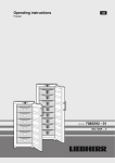
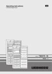
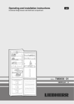
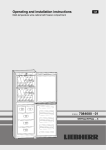
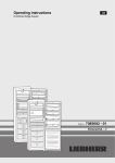
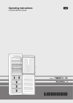
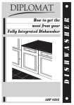
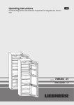
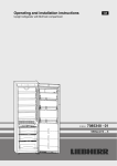
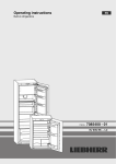
Operating and installation instructions
Multi-temperature wine cabinet with freezer compartment
210514
7084680 - 01
SWTNes/WTNes ... 6
Appliance at a glance
Contents
1
1.1
1.2
1.3
1.4
1.5
1.6
Appliance at a glance............................................
Description of appliance and equipment..................
Range of appliance use............................................
Conformity................................................................
External dimensions of the appliance.......................
Saving energy..........................................................
HomeDialog.............................................................
2
2
2
3
3
3
3
2
General safety information...................................
3
3
3.1
3.2
Controls and displays...........................................
Operating and control elements...............................
Temperature display.................................................
5
5
5
4
4.1
4.2
4.3
4.4
4.5
4.6
4.7
4.8
Putting into operation............................................
Transporting the appliance.......................................
Installing the appliance.............................................
Changing over the door hinges................................
Water connection.....................................................
Insertion into a row of kitchen units...........................
Disposing of packaging............................................
Connecting the appliance.........................................
Switching on the appliance.......................................
5
5
5
6
10
11
11
11
11
5
5.1
5.2
5.3
5.4
5.5
5.6
Control....................................................................
Brightness of the temperature display......................
Child proofing...........................................................
Door alarm................................................................
Temperature alarm...................................................
Freezer compartment...............................................
Wine zone................................................................
12
12
12
12
12
12
14
6
6.1
6.2
6.3
6.4
6.5
Maintenance...........................................................
Replacing the activated charcoal filter......................
Defrosting with NoFrost............................................
Cleaning the appliance.............................................
Cleaning the IceMaker.............................................
Customer service.....................................................
15
15
15
16
16
16
7
Malfunction............................................................. 17
8
8.1
8.2
Decommissioning.................................................. 18
Switching off the appliance....................................... 18
Taking the appliance out of service.......................... 18
9
Disposing of the appliance................................... 18
The manufacturer works constantly on the further development
of all the types and models. Therefore please understand that
we have to reserve the right to make design, equipment and
technical modifications.
To get to know all the benefits of your new appliance, please
read the information contained in these instructions carefully.
The instructions apply to several models. Differences may
occur. Text relating only to specific appliances is marked with
an asterisk (*).
Instructions for action are marked with a
action are marked with a .
, the results of
1 Appliance at a glance
1.1 Description of appliance and equipment
Note
u Shelves, drawers and baskets are arranged for optimum
energy efficiency on delivery.
2
(1) Control panel
(2) LED lighting
(3) Activated charcoal filter,
replaceable
(4) Wooden shelf, folding
(5) Label
(6) Wooden shelf, fixed
(7) Separating plate with
sealing lip
(8) Type plate
Fig. 1
(9) IceMaker
(10) Freezer compartment
(11) Cold storage accumulators
(12) VarioSpace
(13) Information system
(14) Adjustable feet
(15) Transport grips
1.2 Range of appliance use
Intended use
The appliance is suitable solely for cooling wine
and food in a domestic environment or similar.
This includes use in, for example
- in staff kitchenettes, bed and breakfast establishments,
- by guests in country cottages, hotels, motels
and other accommodation,
- for catering and similar services in the wholesale trade.
Use the appliance solely in a domestic type of
environment. All other applications are inadmissible.
Foreseeable misuse
The following applications are expressly
prohibited:
- Storage and cooling of medicines, blood
plasma, laboratory compounds or similar
* Depending on model and options
General safety information
materials and products subject to the Medical 1.4 External dimensions of the appliDevices Directive 2007/47/EC
ance
- Use in potentially explosive areas
Improper use of the appliance can lead to
damage to or spoilage of the stored goods.
Climate rating definitions
The appliance is set to operate within specific
ambient temperature limits according to its
climate rating. The correct climate rating for
your appliance is indicated on the type plate.
Note
uCompliance with the ambient temperatures
indicated is required, otherwise the cooling
performance is reduced.
Climate
rating
for ambient temperatures of
SN
10 °C to 32 °C
N
16 °C to 32 °C
ST
16 °C to 38 °C
T
16 °C to 43 °C
Fig. 2
1.3 Conformity
1.5 Saving energy
The refrigerant circuit is tested for leakage. The appliance
complies with the relevant safety regulations and EC Directives
2006/95/EC, 2004/108/EC, 2009/125/EC and 2010/30/EU.
- Always ensure good ventilation. Do not cover ventilation
Note for test institutions:
Tests are to be carried out according to the applicable
standards and guidelines.
Preparation and testing of the appliances must be carried
out taking the manufacturer's loading plans and the
notes in the operating manual into account.
openings or grille.
- Always keep fan louvres clear.
- Do not place appliance in areas of direct sunlight or next to a
stove, heater or similar object.
- The energy consumption depends on the installation conditions, e.g. the ambient temperature (see 1.2) .
- Keep the time the appliance is open to a minimum.
- The lower the temperature setting, the higher the power
consumption.
Accumulated dust increases the energy
consumption:
- Once a year, dust the refrigerating unit
together with the metal grille of the heat
exchanger at the back of the appliance.
1.6 HomeDialog
Depending on model and options, the HomeDialog system can be used to network a number
of Liebherr appliances (situated, for example, in
the basement) with a main appliance (sited, for
example, in the kitchen) and control them via the
latter. You will find more information on the
benefits, requirements and principle of operation
on the internet at www. liebherr.com.
2 General safety information
Danger for the user:
- This appliance can be used by children of 8
years old and over, and also by persons with
restricted physical, sensory or mental
capacity or lack of experience and knowledge, if they are supervised or have been
* Depending on model and options
3
General safety information
instructed on safe use of the appliance and
understand the resulting risks. Children must
not be allowed to play with the appliance.
Cleaning and user maintenance must not be
carried out by children without supervision.
- When disconnecting the appliance from the
supply, always take hold of the plug. Do not
pull the cable.
- In the event of a fault pull out the mains plug
or deactivate the fuse.
- Do not damage the mains power cable. Do
not operate the appliance with a defective
mains power cable.
- Have any repairs to or intervention in the
appliance, and any change of the mains
power cable, carried out by the customer
service only or by other specialised personnel
trained for the purpose.
- Only assemble, connect and dispose of the
appliance according to the instructions.
- Please keep these instructions in a safe place
and pass them on to any subsequent owners.
- All repairs to and intervention in the IceMaker
may be carried out only by service personnel
or by other skilled personnel trained for the
purpose.
- The manufacturer is not liable for damage
caused by a faulty fixed water connection.
- Special-purpose lamps (incandescent lamps,
LEDs, fluorescent tubes) in the appliance
serve to illuminate the appliance interior and
are not suited for room illumination.
Fire hazard:
- The refrigerant R 600a is environmentally
friendly but flammable. Escaping refrigerant
may ignite.
• Do not damage the refrigerant circuit pipes.
• Do not allow naked flames or ignition
sources to enter the appliance.
• Do not use any electrical appliances in the
interior (e.g. steam cleaners, heaters, ice
cream maker etc.).
• If refrigerant escapes: remove any naked
flames or sources of ignition from the
leakage area. Ventilate the room well.
Notify the after-sales service.
- Do not store explosives or sprays using
combustible propellants such as butane,
propane, pentane, etc. in the appliance. To
identify these spray cans, look for the list of
contents printed on the can, or a flame
symbol. Gases possibly escaping may ignite
due to electrical components.
- Keep burning candles, lamps and other items
with naked flames away from the appliance
so that they do not set the appliance on fire.
4
- Please be sure to store alcoholic drinks or
other packaging containing alcohol in tightly
closed containers. Any alcohol that leaks out
may be ignited by electrical components.
Danger of tipping and falling:
- Do not misuse the plinth, drawers, doors etc.
as a step or for support. This applies particularly to children.
Danger of food poisoning:
- Do not consume food which has been stored
too long.
Danger of frostbite, numbness and pain:
- Avoid lasting skin contact with cold surfaces
or refrigerated/frozen food or take protective
steps, e.g. wear gloves. Do not consume ice
cream, water ice or ice cubes immediately
and do not consume them too cold.
Danger of injury and damage:
- Hot steam can lead to injury. Do not use electrical heating or steam cleaning equipment,
open flames or defrosting sprays to defrost.
- Do not use sharp implements to remove the
ice.
Risk of crushing
- Do not reach into the soft stop mechanism.
Fingers may be trapped when the door is
closed.*
Please observe the specific information in
the other sections:
DANGER
identifies a situation involving direct
danger which, if not obviated, may
result in death or severe bodily
injury.
WARNING
identifies a dangerous situation
which, if not obviated, may result in
death or severe bodily injury.
CAUTION
identifies a dangerous situation
which, if not obviated, may result in
minor or medium bodily injury.
NOTICE
identifies a dangerous situation
which, if not obviated, may result in
damage to property.
Note
identifies useful information and tips.
* Depending on model and options
Controls and displays
3 Controls and displays
4 Putting into operation
3.1 Operating and control elements
4.1 Transporting the appliance
Fig. 3
(1) Alarm button
(2) SuperFrost button
(3) On/Off button, freezer
compartment
(4) Down setting button,
freezer compartment
(5) Up setting button,
freezer compartment
(6) IceMaker symbol
(7) Temperature display,
lower wine zone
(8) Temperature display,
upper wine zone
(9) Upper wine compartment symbol
(10) Light symbol
(11) Power failure symbol
(12) Down setting button,
wine zone
(13) Up setting button, wine
zone
(14) On/Off button, wine zone
(15) Zone button
(16) Light button
(17) Fan button
(18) Child lock symbol
(19) Fan symbol
(20) Menu symbol
(21) HomeDialog symbol
(22) Lower wine compartment
symbol
(23) Freezer compartment
temperature display
(24) SuperFrost symbol
(25) Alarm symbol
3.2 Temperature display
The following are displayed in normal operation:
- the average wine cabinet temperature
- the warmest freezing temperature
The freezer compartment temperature display flashes:
- the temperature setting is being changed
- after switch-on the temperature is not yet cold enough
- the temperature has risen several degrees
The wine zone temperature display flashes:
- the temperature setting is being changed
- after switch-on until the set temperature is reached
- the wine cabinet temperature is too cold/too warm
Dashes flash in the display:
- the freezer temperature is above 0 °C.
The following displays indicate malfunction. Possible causes
and corrective action (see Malfunction).
- F0 to F9
- FE
-
The LED of the power failure symbol
CAUTION
Risk of injury and danger of damage as a result of incorrect
transport!
u Transport the appliance in a packed condition.
u Transport the appliance upright.
u Do not transport the appliance without assistance.
WARNING
Risk of injury due to broken glass!
In case of transport at an altitude of over 1500 m the glass
panes of the door may break. The fragments have sharp edges
and may cause serious injury.
u Take appropriate protective action.
4.2 Installing the appliance
WARNING
Fire hazard due to dampness!
If live parts or the mains lead become damp this may cause
short circuits.
u The appliance is designed for use in enclosed areas. Do not
operate the appliance outdoors or in areas where it is
exposed to splash water or damp conditions.
WARNING
Risk of fire due to short circuit!
If the mains cable/connector of the appliance or of another
appliance touch the rear of the appliance, the mains cable/
connector may be damaged by the appliance vibrations,
leading to a short circuit.
u Stand the appliance so that it is not touched by connectors
or main cables.
u Do not plug the appliance or any others into sockets located
near the rear of the appliance.
WARNING
Fire hazard due to refrigerant!
The refrigerant R 600a is environmentally friendly but flammable. Escaping refrigerant may ignite.
u Do not damage the piping of the refrigeration circuit.
WARNING
Fire hazard and danger of damage!
u Do not place appliances emitting heat e.g. microwaves,
toasters etc. on the appliance!
flashes.
WARNING
Blocked ventilation openings pose a risk of fire and damage!
u Always keep the ventilation openings clear. Always ensure
that the appliance is properly ventilated!
* Depending on model and options
5
Putting into operation
NOTICE*
Risk of damage due to condensate!
If your appliance is not a Side-by-Side (SBS) appliance:
u do not install the appliance directly alongside a further refrigerator/freezer.
q In the event that the appliance is damaged, contact the
supplier immediately before connecting to the mains.
q The floor at the site must be flat and level.
q Do not install the appliance in a location where it is exposed
to direct radiation of the sun, next to a cooker, heater and
similar.
q The appliance may be moved only when it is empty.
q Do not install the appliance without assistance.
q The more R 600a refrigerant there is in the appliance, the
larger the room in which the appliance is standing needs to
be. In rooms that are too small, a flammable mix of gas and
air may be created if there is a leak. According to the EN
378 standard, every 11 g of R 600a refrigerant requires at
least 1 m3 space in the room for the appliance. The amount
of refrigerant in your appliance is on the type plate inside the
appliance.
u Detach the connecting cable from the rear of the appliance,
removing the cable holder at the same time because otherwise there will be vibratory noise!
u Remove the protective film from the outside of the appliance.
4.3 Changing over the door hinges
You can change over the door hinges if necessary.
NOTICE
Risk of damage to side-by-side appliances due to condensation!
When a side-by-side appliance (S…) is fitted together with a
second appliance (as a SBS combination), the door hinges
must remain as delivered.
u Do not change over the door hinges.
Ensure that the following tools are to hand:
q Torx® 25
q Torx® 15
q Screwdriver
q Cordless screwdriver, if necessary
q Second person for fitting work, if needed
q Accompanying Allen key size 2*
4.3.1 Detaching the upper soft stop mechanism
NOTICE
The stainless steel doors are provided with a high-quality
surface coating and must not be treated using the accompanying care product.
Otherwise the surface coating will be affected.
u Wipe the coated door surfaces using a soft, clean cloth
only.
u Apply a stainless steel cleaner only to the stainless steel
side walls evenly, wiping with the grain. Subsequent
cleaning becomes easier as a result.
u Wipe side walls with a paint finish using a soft, clean
cloth only.
u Remove the protective film from the decorative trims and
drawer fronts.
u Remove all transit supports.
u Dispose of packaging material (see 4.6) .
u Align the appliance so that it
stands firmly and on a level by
applying the accompanying
spanner to the adjustableheight feet (A) and using a
spirit level.
u Then support the door: Extend
the adjustable foot at the turn
hinge (B) until it rests on the
floor and then make a further
90° turn.*
When a Side-by-Side appliance (S…) is fitted together with
a second appliance (as a SBS combination):
u Proceed according to the Side-by-Side combined fridgefreezer installation instructions. (Accessories bag of the SBS
freezer/appliance with freezer compartment)*
Note
u Clean the appliance (see 6.3) .
If the appliance is installed in a very damp environment,
condensate may form on the outside of the appliance.
u Always see to good ventilation at the installation site.
6
Fig. 4
u Open the upper door.
NOTICE
Risk of damage!
If the door seal is damaged, the door may fail to close properly
and the cooling will be inadequate.
u Do not damage the door seal with the screwdriver!
u Disengage and remove the faceplate Fig. 4 (1) using a flatblade screwdriver.
w The faceplate is attached over the soft stop bracket.
Fig. 5
u Slide the faceplate forwards over the soft stop bracket
Fig. 5 (4) in the direction of the appliance.
u Snap the safety lock Fig. 5 (2) into the oblong hole.
w The safety lock prevents the hinge from snap-closing.
u Using a screwdriver, detach the cover Fig. 5 (5) on the hinge
side as far as the first detent.
w The pin becomes visible.
* Depending on model and options
Putting into operation
u Press the pin Fig. 5 (3) out from underneath.
u Press the soft stop bracket Fig. 5 (4) towards the door.
u Fully detach the cover Fig. 5 (5) on the hinge side and
remove it.
u Remove the faceplate Fig. 5 (1).
u Using a screwdriver, detach the
cover on the handle side
Fig. 6 (6) and draw it outwards for
removal.
Fig. 6
u Open the lower door.
NOTICE
Risk of damage!
If the door seal is damaged, the door may fail to close properly
and the cooling will be inadequate.
u Do not damage the door seal with the screwdriver!
u Disengage and remove the faceplate Fig. 9 (20) using a flatblade screwdriver.
w The faceplate is attached over the soft stop bracket.
u Unscrew the soft stop unit (2x Torx® 15) Fig. 5 (7).
u Pull the soft stop unit out a little, push it in the direction of the
handle side and swing it out.
u Set the soft stop unit aside.
the
bearing
u Unscrew
element Fig. 5 (8), turn it
180° and transfer it to the
opposite side. Possibly
make preliminary holes with
a bradawl or use a cordless
screwdriver.
Fig. 7
4.3.2 Detaching the upper door
Fig. 10
u Slide the faceplate forwards over the soft stop bracket
Fig. 10 (24) in the direction of the appliance.
u Snap the safety lock Fig. 10 (22) into the oblong hole.
w The safety lock prevents the hinge from snap-closing.
u Using a screwdriver, lift off the cover Fig. 10 (21) from the
outside and remove it in an outward direction.
u If necessary, tip the appliance backwards with the assistance of a second person.
u Press the pin Fig. 10 (23) out from underneath.
u Press the soft stop bracket Fig. 10 (24) towards the door.
u Remove the faceplate Fig. 10 (20).
u Unscrew the entire soft stop unit (2x Torx® 15) Fig. 10 (25).
u Pull the soft stop unit out a little, push it in the direction of the
handle side and swing it out.
u Set the soft stop unit aside.
4.3.4 Detaching the lower door
Fig. 8
u Close the upper door.
u Pull off the cover Fig. 8 (10) forwards and upwards.
u Lift off the cover Fig. 8 (11).
u Close the lower door.
u Draw the middle bearing pin Fig. 11 (32) together with the
washer Fig. 11 (34) out of the turn hinge and lower door.
u Remove the plastic cap Fig. 11 (33).
CAUTION
Risk of injury if the door tips!
u Take good hold of the door.
u Set down the door carefully.
CAUTION
Risk of injury if the door tips!
u Take good hold of the door.
u Set down the door carefully.
u Unscrew the upper turn hinge Fig. 8 (12)(2x Torx® 25)
Fig. 8 (13) and lift it off.
u Lift off the upper door and set it aside.
u Open the lower door.
u Unscrew the middle turn hinge (2x Torx® 25). Fig. 11 (31)
u Lift off the lower door and set it aside.
4.3.3 Detaching the lower soft stop mechanism
Fig. 9
* Depending on model and options
7
Putting into operation
4.3.5 Transferring the middle bearing elements
u Unscrew Fig. 12 (46)the turn hinge Fig. 12 (45).
u Unscrew the bearing element Fig. 12 (48), turn it through
180° and screw it firmly into place again inside
u Carefully lift off the cover on the handle side Fig. 12 (47) and
transfer it to the opposite side.
u Screw the bottom turn hinge Fig. 12 (45) firmly into place
(with 4 Nm) on the new hinge side, possibly using a cordless
screwdriver.
u Re-insert the stopper Fig. 12 (41) into the other hole.
u Re-insert the bearing pin Fig. 12 (42) together with the
washer and adjustable-height foot. In so doing, pay attention
that the locating lug points backwards
4.3.8 Transferring the lower bearing elements
For appliances with height adjustment
Fig. 11
u Carefully detach the cover panel Fig. 11 (30).
u Turn the middle turn hinge Fig. 11 (31) with the washer
Fig. 11 (35) through 180° and screw it firmly into place on
the new hinge side (with 4 Nm).
u Turn the cover panel Fig. 11 (30) through 180° and snap it
into place again on the new handle side.
4.3.6 Distinguishing between bearing elements
Some appliances are height-adjustable, as can be noted from
the bearing pin in the lower turn hinge:
u For appliances without
height
adjustment,
continue
with
item
(see 4.3.7) .
Fig. 13
appliances
with
u For
height
adjustment,
continue
with
item
(see 4.3.8) .
4.3.7 Transferring the lower bearing elements
For appliances without height adjustment
u Using the accompanying Allen key, unscrew the threaded
pin Fig. 13 (60) by about 1 turn.
u Turn and lift out the bearing pin Fig. 13 (42) together with the
washer Fig. 13 (43) and adjustable-height foot Fig. 13 (44).
u Lift out the stopper Fig. 13 (41).
u Unscrew Fig. 13 (46)the turn hinge Fig. 13 (45).
u Fully unscrew the threaded pin Fig. 13 (60) and screw it in
on the opposite side, at the turn hinge, until it is flush outside
with the turn hinge.
u Unscrew the bearing element Fig. 13 (48), turn it through
180° and screw Fig. 13 (49)it firmly back into place.
u Re-insert the stopper Fig. 13 (41) into the other hole.
u Carefully lift off the cover on the handle side Fig. 13 (47) and
transfer it to the opposite side.
u Screw the turn hinge Fig. 13 (45) firmly into place on the
new hinge side, possibly using a cordless screwdriver (with
4 Nm).
u Screw the bearing pin Fig. 13 (42) into place again,
complete with washer and adjustable-height foot.
u Tighten the threaded pin Fig. 13 (60).
4.3.9 Transferring the handles
On both the top and bottom doors:
Fig. 12
u Lift out the bearing pin Fig. 12 (42) together with washer
Fig. 12 (43) and adjustable-height foot Fig. 12 (44).
u Lift out the stopper Fig. 12 (41).
8
* Depending on model and options
Putting into operation
Fig. 14
u Lift the stopper Fig. 14 (50) out of the door bearing bush and
transfer it.
u Detach door handle Fig. 14 (52), stopper Fig. 14 (53) and
pressure plates Fig. 14 (54) and transfer to the opposite
side.
u When fitting the pressure plates on the opposite side, make
sure they snap properly into place.*
4.3.10 Fitting the lower door
u Place the door from above onto the lower bearing pin
Fig. 13 (42).
u Close the door.
u Place the plastic cap Fig. 11 (33) back onto the middle turn
hinge Fig. 11 (31).
u On the new hinge side, pass the middle bearing pin
Fig. 11 (32) through the middle turn hinge Fig. 11 (31) into
the lower door.
u Attach the washer Fig. 11 (34) to the middle bearing pin
Fig. 11 (32).
4.3.11 Fitting the lower soft stop mechanism
Fig. 16
u Attach the faceplate Fig. 16 (20) to the soft stop bracket so
that the catches face forwards and the front faces the appliance.
u Draw the soft stop bracket Fig. 16 (24) towards the bearing
element and insert the pin Fig. 16 (23) from above so that
the square is seated in the depression.
u Attach and engage the cover Fig. 16 (21).
w Pay attention that the cover fits properly so that the door
closes properly and the pin is secured.
u Twist the safety lock Fig. 16 (22) for removal.
u Snap thefaceplate Fig. 16 (20) onto the door.
u Close the lower door.
4.3.12 Fitting the upper door
u Place the upper door on the middle bearing pin Fig. 11 (32).
u Insert the upper turn hinge Fig. 8 (12) in the door on the new
hinge side.
u Screw the upper turn hinge firmly into place (with 4 Nm)
(2xTorx® 25) Fig. 8 (13). Possibly make preliminary holes
with a bradawl or use a cordless screwdriver.
u Snap the cover Fig. 8 (11) and cover Fig. 8 (10) into place at
the opposite side.
u Leave the upper door open.
4.3.13 Fitting the upper soft stop mechanism
Fig. 15
u Remove the cover Fig. 15 (26) from the faceplate
Fig. 15 (20) and re-insert it at the other side.
u Engage the soft stop unit with the joint pointing to the hinge
side (A) and swivel into place (B).
w The screw holes at the left and right have to register.
u Screw the soft stop unit firmly into place(2 mal Torx® 15)
Fig. 15 (25).
Fig. 17
u Remove the cover Fig. 17 (9) from the faceplate Fig. 17 (1)
and re-insert it at the other side.
u Engage the upper soft stop unit with the joint on the hinge
side (A) and swivel into place (B).
w The screw holes at the left and right have to register.
u Screw the soft stop unit firmly into place(2 mal Torx® 15)
Fig. 17 (7).
Note
u Keep to the correct order. First attach the panel over the soft
stop bracket, then the cover.
* Depending on model and options
9
Putting into operation
WARNING
Risk of poisoning!
u The water quality has to comply with the drinking water ordinance of the respective country (e.g. 98/8
u Connect to the drinking water supply only.
u The IceMaker serves exclusively for making ice cubes in
household quantities and has to be operated with water suitable for the purpose.
Fig. 18
u Attach the faceplate Fig. 18 (1) to the soft stop bracket
Fig. 18 (4) so that the catches face inwards and the front
faces the appliance.
u Slide on the cover Fig. 18 (5) from the outside (A) and swivel
it over the bearing element Fig. 18 (8) (B).
u Attach the cover Fig. 18 (5) and engage it as far as the first
detent.
w The openings for the pin are on top of one another after the
soft stop bracket has been positioned.
u Draw the soft stop bracket Fig. 18 (4) towards the bearing
element and insert the pin Fig. 18 (3) from above so that the
square is seated in the depression.
u Now completely snap the cover Fig. 18 (5) onto the bearing
element Fig. 18 (8).
w Pay attention that the cover fits properly so that the door
closes properly and the pin is secured.
u Twist the safety lock Fig. 18 (2) for removal.
u Snap thefaceplate Fig. 18 (1) onto the door.
u Turn the cover Fig. 6 (6) through 180°, attach and engage it
on the handle side.
4.3.14 Aligning the doors
u If necessary, align the doors to the appliance housing by
way of the two oblong holes in the bottom turn hinge
Fig. 13 (45) and middle turn hinge Fig. 11 (31). To do so,
unscrew the middle screw in the bottom turn hinge
Fig. 13 (45).
-
-
Fig. 19
The water pressure has to be between 0.15 MPa and
0.6 MPa (1.5 bar - 6 bar).
The water supply to the appliance must be via a cold water
pipe which withstands the operating pressure and complies
with the hygiene regulations.
Use the accompanying stainless steel hose (1.5 m). Do not
reuse old hoses. A 3 m hose is available from the customer
service department and has to be fitted by an expert.
In the hose connecting piece is a sieve with seal.
Between the hose and the domestic water connection there
has to be a stopcock to interrupt the water supply in case of
need.
All the fixtures and fittings used for water supply have to
comply with the applicable regulations of the respective
country.
Do not damage or kink the water inlet pipe when installing
the appliance.
WARNING
Risk of injury due to the door dropping out!
If the bearing parts are not screwed into place firmly enough,
the door may drop out. This may lead to severe injuries. What
is more, the door may not close and therefore the appliance
may fail to cool properly.
u Screw the turn hinges firmly into place with 4 Nm.
u Check all of the screws and retighten if necessary.
4.4 Water connection
WARNING
Danger of electric shock!
u Disconnect the appliance by unplugging it before you
connect it to the water line.
u Shut off the water supply before you connect the water feed
lines of the IceMaker.
u The connection to the drinking water system may be carried
out only by a qualified gas fitter and plumber.
10
Fig. 20
u Connect the straight part of the accompanying stainless
steel hose to the stopcock.
The solenoid valve is at the bottom back of the appliance. It
has a metric R3/4 connecting thread.
u Connect the angled part of the stainless steel hose to the
solenoid valve.
* Depending on model and options
Putting into operation
4.6 Disposing of packaging
u Open the stopcock of the water supply and
check that the entire water system is leakproof.
Before initial use:
u Have the water pipe bled of air by the proper
expert.
4.5 Insertion into a row of kitchen units
WARNING
Danger of suffocation due to packing material and plastic film!
u Do not allow children to play with packing material.
The packaging is made of recyclable materials:
- corrugated board/cardboard
- expanded polystyrene parts
- polythene bags and sheets
- polypropylene straps
- nailed wooden frame with polyethylene panel*
u Take the packaging material to an official collecting point.
4.7 Connecting the appliance
NOTICE
Risk of damage to the electronic control system!
u Do not use stand-alone inverters (conversion of d.c. to a.c./
three-phase) or energy saving plugs.
WARNING
Fire and overheating hazard!
u Do not use extension cables or multiple socket outlets.
Fig. 21
(1) Stack cabinet
(3) Kitchen cabinet
(2) Appliance
(4) Wall
The appliance can be inserted into a row of kitchen units. To
match the appliance Fig. 21 (2) to the height of the row of units,
a suitable stack cabinet Fig. 21 (1) can be fitted above the
appliance.
When inserting the appliance into a row of kitchen units (max.
depth 580 mm), the appliance can be installed directly next to
the kitchen unit Fig. 21 (3). The appliance door projects relative
to the front of the kitchen unit by 34 mm at the side and by
50 mm in the middle of the appliance. It can be opened and
closed perfectly as a result.
Ventilation requirements:
- At the back of the stack cabinet there has to be a ventilation
duct of at least 50 mm depth throughout the width of the
stack cabinet.
- the larger the ventilation space, the more energy-saving the
appliance is in operation.
If the appliance is installed with the hinges next to a wall
Fig. 21 (4), the distance between appliance and wall has to be
at least 40 mm. This corresponds to the projection of the
handle when the door is open.
* Depending on model and options
The type of current (alternating current) and voltage at the
installation site have to conform with the data on the type plate
(see Appliance at a glance).
The socket must be properly earthed and fused. The tripping
current for the fuse must be between 10 A and 16 A.
The socket must be easily accessible so that the appliance can
be quickly disconnected from the supply in an emergency. It
must be outside the area of the rear of the appliance.
u Check the electrical connection.
u Plug in the power plug.
4.8 Switching on the appliance
Note
u To switch on the entire appliance it is necessary only to
switch on the freezer compartment.
Switch on the appliance approx. 2 hours before
adding frozen food for the first time.
Do not load food to be frozen before the temperature display reads -18 °C.
4.8.1 Switching on the freezer compartment
u Press On/Off button, freezer compartment Fig. 3 (3).
w The temperature display of the multi-temperature wine zone
and the alarm symbol flash until the set temperature is
reached.
w The temperature display of the freezer compartment and the
alarm symbol flash until the temperature is sufficiently low. If
the temperature is above 0 °C, dashes flash. If it is below,
the current temperature flashes.
w If “DEMO” is displayed, demo mode is activated. Please
contact the after sales service.
11
Control
5 Control
5.1 Brightness of the temperature
display
You can adjust the brightness of the temperature display to the
light conditions of the room in which the appliance is installed.
5.1.1 Adjusting the brightness
The brightness is adjustable between h0 (no illumination) and
h5 (maximum luminosity).
u To activate the setting mode: press the SuperFrost button
Fig. 3 (2) for about 5 s.
w The display indicates c.
w The menu symbol Fig. 3 (20) shines.
u Using the Up setting button, freezer compartment Fig. 3 (5)
or Down setting button, freezer compartment Fig. 3 (4),
select h.
u To confirm: briefly press the SuperFrost button Fig. 3 (2).
u To make the display brighter: press Up button,
freezer compartment Fig. 3 (5).
u To make the display darker: press Down button,
freezer compartment Fig. 3 (4).
u To confirm: press SuperFrost button Fig. 3 (2).
w The brightness is adjusted to the new value.
u To deactivate the set-up mode: press On/Off button, freezer
compartment Fig. 3 (3).
-oru Wait for 5 minutes.
w The temperature is indicated again in the temperature
display.
5.2 Child proofing
The child-proofing function enables you to make
sure that the appliance is not inadvertently switched
off by playing children.
5.2.1 Setting the child lock function
u To activate the setting mode: press SuperFrost button
Fig. 3 (2) for about 5 s.
w c flashes on the display.
w The menu symbol Fig. 3 (20) shines.
u Briefly press the SuperFrost button Fig. 3 (2).to confirm.
When c1 is indicated in the display:
u Tto activate the child lock, briefly press the
SuperFrost button Fig. 3 (2).
w The LED of the child lock symbol Fig. 3 (18) shines. c
flashes in the display.
When c0 is indicated in the display:
u to deactivate the child lock, briefly press the SuperFrost
button Fig. 3 (2).
w The LED of the child lock symbol Fig. 3 (18) goes out. c
flashes in the display.
u To deactivate the set-up mode: press On/Off button, freezer
compartment Fig. 3 (3).
-oru Wait for 5 minutes.
w The temperature is indicated again in the temperature
display.
5.3 Door alarm
For refrigerator and freezer compartment
12
If the door is open for longer than 60 seconds, the
audible warning will sound.
The audible alarm is automatically silenced when
the door is closed.
5.3.1 Muting the door alarm
w The temperature is indicated in the display. The display
changes to the normal temperature display.
5.4 Temperature alarm
The audible alarm sounds if the freezer temperature
is not cold enough.
At the same time, the temperature display and LED
of the alarm symbol Fig. 3 (25) flashes.
The cause of the temperature being too high may be:
- too much warm ambient air flowed in when rearranging and
removing food
- power failure for some time
- the appliance is faulty
The audible alarm is automatically silenced, the alarm symbol
Fig. 3 (25) goes out and the temperature display stops flashing
when the temperature is sufficiently cold/warm again.
If the alarm status persists: (see Malfunction).
Note
Food may be spoilt if the temperature is not cold enough.
u Check the quality of the food. Do not consume spoiled food.
5.4.1 Muting the temperature alarm
The audible alarm can be muted. When the temperature is
sufficiently cold again, the alarm function is active again.
u Press alarm button Fig. 3 (1).
w The audible alarm is silenced.
5.5 Freezer compartment
You can store frozen food, make ice cubes and freeze fresh
food in the freezer compartment.
5.5.1 Freezing food
The rating plate indicates the maximum quantity of fresh food
you can freeze within 24 hours (see Appliance at a glance)
under “Freezing capacity ... kg/24h”.
The maximum load of frozen food for the drawers is 25 kg each
and for the shelves 35 kg each.
CAUTION
Risk of injury due to broken glass!
Bottles and cans containing drinks may burst when being
frozen. This applies particularly to sparkling drinks.
u Do not freeze bottles and cans containing drinks!
In order that the food is rapidly frozen through to the core, do
not exceed the following quantities per pack:
- Fruit, vegetables up to 1 kg
- Meat up to 2.5 kg
u Pack the food in portions in freezer bags, reusable plastic,
metal or aluminium containers.
5.5.2 Thawing food
- in the refrigerator compartment
- in a microwave oven
- in a conventional or fan oven
* Depending on model and options
Control
- at room temperature
u Food once thawed should be re-frozen only in exceptional
cases.
5.5.3 Setting the temperature in the freezer
compartment
The appliance is pre-set for normal operation.
The temperature can be set between -16 °C and -26 °C, the
recommended temperature is -18 °C.
u To set the temperature higher: press Up button, freezer
compartment Fig. 3 (5).
u To set the temperature lower: press Down button, freezer
compartment Fig. 3 (4).
w When the button is pressed the first time, the previous value
is indicated in the temperature display of the freezer
compartment.
u To change the temperature in 1 °C steps: briefly press the
button.
-oru To change the temperature continuously: hold down the
button.
w The value is displayed flashing during the setting operation.
w The actual temperature is displayed approx. 5 seconds after
the button is last pressed. The temperature gradually
adjusts to the new value.
5.5.4 SuperFrost
With this function you can freeze fresh food quickly
through to the core. The appliance operates with
maximum refrigeration. The noise of the refrigeration
unit may be temporarily louder as a result.
The maximum amount of fresh food which can be frozen in 24
h is indicated on the type plate under “freezing capacity ... kg/
24h”. This amount varies according to the model and climate
rating.*
You have to activate SuperFrost in good time, depending on
how much fresh food is to be frozen: about 6 hours before
placing the food inside in case of small amounts and about 24
hours in advance in case of the maximum amount of food to be
frozen.
Wrap produce and spread it out as far as possible. Do not
allow produce to be frozen to touch produce that is already
frozen to prevent the latter thawing.
You do not have to activate SuperFrost in the following cases:
- when placing frozen food in the freezer
- when freezing up to approx. 2 kg fresh food daily
Freezing with SuperFrost
u Briefly press the SuperFrost button Fig. 3 (2) once.
w The LED of the SuperFrost symbol Fig. 3 (24) shines.
w The freezing temperature drops, the appliance operates with
the maximum cooling capacity.
For a smaller quantity of produce to be frozen:
u wait approx. 6 h.
u Place wrapped produce in the top drawers.
For the maximum quantity of produce to be frozen:
u wait approx. 24 h.
u Remove top drawers and place produce directly on the top
shelves.
w SuperFrost is automatically deactivated. Depending on the
quantity placed inside, after 30 h at the earliest, 65 h at the
latest.
w The LED on the SuperFrost symbol Fig. 3 (24) extinguishes
once freezing is completed.
u Place produce in the drawers and push the latter back in
again.
w The appliance continues to operate in the energy-saving,
normal mode.
* Depending on model and options
5.5.5 Drawers
Note
The energy consumption increases and the cooling performance decreases if there is insufficient ventilation.
For appliances with NoFrost:
u Leave the bottom drawer in the appliance!
u Always keep the air slits of the fan free at the rear wall!
u To store frozen food directly on the shelves: pull the drawer
forwards and lift it out.
5.5.6 Shelves
u To remove the shelf: lift up at the front
and pull out.
u To put the shelf back: simply push in as
far as it will go.
*
5.5.7 VarioSpace
Apart from being able to remove
the drawers, you can also
remove the shelves, creating
space for large items of frozen
food. Poultry, meat, large pieces
of game and high bakery products can be frozen in one piece
and prepared.
u The maximum load of frozen
food for the drawers is 25 kg
each and for the shelves
35 kg each.
5.5.8 Information system
Fig. 22
(1) Ready-made meals, ice
(4) Sausages, bread
cream
(2) Pork, fish
(5) Game, mushrooms
(3) Fruit, vegetables
(6) Poultry, beef/veal
The figures indicate the storage time in months for several
types of frozen food in each case. Storage times given are
guide times.
5.5.9 Cold storage accumulators
The cold storage accumulators prevent the temperature from
rising too fast in the event of power failure.
13
Control
Using cold storage accumulators
u Place the cold storage accumulators in the top freezer compartment to save space.
u Place the frozen cold storage
accumulators on the frozen food
in the upper front area of the
freezer compartment.
5.5.10 IceMaker
The IceMaker is in the top drawer of the freezer compartment.
The drawer is marked “IceMaker”.
Make certain that the following conditions are met:
- The appliance is level.
- The appliance is connected.
- The freezer compartment is switched on.
- The IceMaker is connected to the water supply.
Switching on the IceMaker
Fig. 23
u Pull out the drawer.
u Press the On/Off button Fig. 23 (1) so that the LED
Fig. 23 (2) shines.
u Push in the drawer.
w The LED of the IceMaker symbol Fig. 3 (6) shines.
Note
u The IceMaker produces ice cubes only if the drawer is fully
closed.
Producing ice cubes
The production capacity depends on the freezer temperature.
The lower the temperature, the more ice cubes can be
produced in a specific period.
The ice cubes drop from the IceMaker into the drawer. When a
certain filling level has been reached, no further ice cubes are
produced. The IceMaker does not fill the drawer right up to the
brim.
If large quantities of ice cubes are needed, the complete
IceMaker drawer can be exchanged for the adjacent drawer.
When the drawer is closed, the IceMaker automatically recommences production.
Once the IceMaker has been switched on for the first time, it
may take up to 24 hours until the first ice cubes are produced.
Note
When the appliance is used for the first time and if it has been
out of use for a long time, particles may collect in the IceMaker
and/or water conduit.
u Therefore do not use or consume the ice cubes made in the
first 24 hours.
Setting the water intake time
The opening time of the IceMaker valve can be set if, for
example, the water pressure in the pipe is too low or too high.
The water intake time can be set in stages from E1 (short intake
time) to E8 (long intake time). The intake is preset at E3.
u To activate the setting mode: press the SuperFrost button
Fig. 3 (2) for about 5 s.
w The display indicates c.
w Themenu symbol Fig. 3 (20) shines.
14
u Using the Up setting button, freezer compartment Fig. 3 (5)
and Down setting button, freezer compartment Fig. 3 (4)
select E.
u To confirm: briefly press the SuperFrost button Fig. 3 (2).
u To increase the water intake time: press the Up
setting button, freezer compartment Fig. 3 (5).
u To reduce the water intake time: press the
Down setting button, freezer compartment
Fig. 3 (4).
u To confirm: press the SuperFrost button
Fig. 3 (2).
u To deactivate the setting mode: press the On/Off button,
freezer compartment Fig. 3 (3).
-oru Wait for 5 minutes.
w The temperature is indicated again in the temperature
display.
Switching off the IceMaker
If no ice cubes are needed, the IceMaker can be switched off
independently of the freezer compartment.
When the IceMaker is switched off, the IceMaker drawer can
also be used for freezing and storing food.
u Press the On/Off button for about 1 second until the LED
goes out.
w The LED of the IceMaker symbol Fig. 3 (6) goes out.
u Clean the IceMaker.
w This ensures that no water or ice remains in the IceMaker.
5.6 Wine zone
You can bring your wines to the ideal drinking temperature
slowly and gradually in the wine zone.
5.6.1 Storing wine bottles
41 Bordeaux bottles(0,75 l) can be stored in the wine zone.
u Store white wine only in one compartment and red wine only
in the other, since both compartments can be set to independent temperatures.
u If possible, lay bottles of the same type of wine side by side
on the same grid shelf.
u Rearrange bottles as seldom as possible.
u Stored open bottles on the
folded down wooden grid
shelf.
u To fold down the wooden
grid shelf: press the lock
under the trim sideways.
w The wooden grid shelf folds
down.
5.6.2 Setting the temperature in the wine zone
The appliance is pre-set for normal operation. The temperature
can be set from 20 °C to 5 °C, the recommended temperatures
are 8 °C to 12 °C.
The wine zone is divided into two wine compartments, which
can be set to different temperatures, as needed.
u To select the wine compartment: press the zone button
Fig. 3 (15).
w The selected wine compartment is indicated in
the temperature display.
u To set the temperature warmer: press the Up setting button,
wine zone Fig. 3 (13).
u To set the temperature colder: press the Down setting
button, wine zone Fig. 3 (12).
* Depending on model and options
Maintenance
w The first time the button is pressed, the previous value is
indicated in the temperature display, upper wine zone
Fig. 3 (8) or in the temperature display, lower wine zone
Fig. 3 (7).
u To change the temperature in 1 °C steps: briefly press the
button.
-oru To change the temperature continuously: hold down the
button.
w During setting the new value is displayed flashing.
w The actual temperature is displayed about 5 s after the last
press of a button. The temperature slowly adjusts to the new
value.
5.6.3 Fan
When the fan runs, the relative humidity in the interior
increases so that the cork does not dry out.
When the fan is activated, the energy consumption increases.
To save energy, the fan switches off automatically when the
door is open.
Switching on the fan
5.6.6 Wooden shelf
Pay attention that the wooden
shelf does not get caught on the
rear hook.
u To remove the folding
wooden shelf: lift it off the
pull-out rail and draw it
forwards.
u To insert the wooden folding shelf: slide it under the rear
hook and press onto the rails so that they audibly snap into
place.
u To remove lower wooden
shelf: pull it forwards at an
angle and simultaneously
raise it.
u To insert lower wooden shelf:
slide it in over the stop on the
intervening shelves up to the
rear wall of the appliance and
press it down.
u To insert other wooden
shelves: place on the rails.
u Briefly press the fan button Fig. 3 (17).
w The LED of the fan symbol shines.
*
Switch off the fan
u Briefly press the fan button Fig. 3 (17).
w The LED of the fan symbol is dark.
w The fan runs only when this is necessary for temperature
control. The humidity is low.
5.6.4 Dim mode
For glazed door models you can set the dim mode of the light,
i.e. the intensity with which the light is to shine after the door
has closed.
Setting the dim mode
Note
u When the dim mode is deactivated, the light becomes
slowly darker after the door has closed and then goes out.
u Briefly press the Light button Fig. 3 (16).
w The Light button Fig. 3 (16) shines. The dim mode is activated.
The settings apply to all wine compartments.
u For a brighter light adjustment: press Light button Fig. 3 (16)
and Up setting button, wine zone Fig. 3 (13) at the same
time.
u For a darker light adjustment: press Light button Fig. 3 (16)
and Down setting button, wine zone Fig. 3 (12) at the same
time.
5.6.5 Labels
You can note down on the labels the type of wine stored in the
respective compartment. Additional labels can be obtained
from your specialist dealer.
Labelling
* Depending on model and options
6 Maintenance
6.1 Replacing the activated charcoal
filter
The activated charcoal filter ensures ideal air quality and
should therefore be replaced annually. It can be ordered from a
specialised dealer.
Each wine zone is equipped with an activated charcoal filter of
its own.
u Take the activated charcoal filter by
the grip.
u Turn the activated charcoal filter
through 90° to the right or left
Fig. 24 (1).
u Remove Fig. 24 (2) the activated charcoal filter.
u Insert the new activated charcoal filter
Fig. 24
with the grip in an upright position.
u Turn the new activated charcoal filter
through 90° to the right or left
Fig. 24 (1) until it snaps into place.
6.2 Defrosting with NoFrost
The NoFrost system automatically defrosts the appliance.
Wine zone:
The defrost water evaporates due to the compressor heat.
Drops of water on the rear wall are perfectly normal.
u Regularly clean the drain opening to allow the water to flow
away (see 6.3) .
u Clean the rubber lip (see 6.3) .
Freezer compartment:
The moisture condenses on the evaporator, is periodically
defrosted and evaporates.
u The appliance does not have to be manually defrosted.
15
Maintenance
6.3 Cleaning the appliance
u Switch on SuperFrost (see 5.5.4) .
When the temperature is sufficiently cold:
u Put the food back inside.
WARNING
Risk of injury and damage as a result of hot steam!
Hot steam can lead to burns and can damage the surfaces.
u Do not use any steam cleaners!
6.4 Cleaning the IceMaker
NOTICE
Incorrect cleaning damages the appliance!
u Do not use cleaning agents in concentrated form.
u Do not use any scouring or abrasive sponges or steel wool.
u Please do not use any aggressive, scouring, sand-,
chloride-, chemical- or acid-based cleaning agents.
u Do not use chemical solvents.
u Do not damage or remove the type plate on the inside of the
appliance. It is important for the customer service.
u Do not pull off, bend or damage cables or other components.
u Do not allow any cleaning water to enter the drain channel,
ventilation grille or electrical parts.
u Please use soft cleaning cloths and a universal pH-neutral
cleaning agent.
u Please use cleaning and care products suitable for contact
with foodstuffs in the appliance interior.
u Empty appliance.
u Pull out the power plug.
u Clean plastic outer and inner surfaces with lukewarm
water and a little washing-up liquid.
Do not apply stainless steel cleaning agent to glass or plastic
surfaces to prevent them from being scratched. Darker areas at
the beginning and quite an intensive colour of the stainless
steel surface are normal.
NOTICE
The stainless steel doors are provided with a high-quality
surface coating and must not be treated using the accompanying care product.
Otherwise the surface coating will be affected.
u Wipe the coated door surfaces using a soft, clean cloth
only. In case of stubborn dirt, use a little water or a neutral
cleaning agent. A microfibre cloth can be optionally used.
u If the stainless steel side walls are dirty, clean them using
a commercially available stainless steel cleaning agent.
Then evenly apply the accompanying stainless steel care
product, making strokes in the direction of the grain.
u Wipe side walls with a paint finish using a soft, clean
cloth only. In case of stubborn dirt, use a little water or a
neutral cleaning agent. A microfibre cloth can be optionally
used.
Do not clean the glass door with abrasive cleaning agents or
rough cloths. Otherwise the surface and the frame may
become dull or be scratched.
u Clean the glass door with a standard glass cleaning agent
and a soft cloth.
u Wipe wooden grid shelves with a dry lint-free cloth.
Note
u Do not clean wooden grid shelves with water and washingup liquid.
u Clean other items of equipment by hand with lukewarm
water and a little washing-up liquid.
After cleaning:
u Wipe dry the appliance and items of equipment.
u Connect the appliance and switch it on again.
16
The drawer of the IceMaker has to be emptied and slid in.
u To activate the setting mode: press the SuperFrost button
Fig. 3 (2) for about 5 s.
w The display indicates c.
w The menu symbol Fig. 3 (20) shines.
u Using the Up setting button, freezer compartment Fig. 3 (5)/
Down setting button, freezer compartment Fig. 3 (4) select I.
u To confirm: press the SuperFrost button Fig. 3 (2).
u Using the Up setting button, freezer compartment Fig. 3 (5)/ Down setting button, freezer
compartment Fig. 3 (4) select Ic.
u To confirm: press the SuperFrost button
Fig. 3 (2).
w The IceMaker moves into the cleaning position and switches
off.
u To deactivate the setting mode: press the On/Off button,
freezer compartment Fig. 3 (3).
-oru Wait for 2 minutes.
w The temperature is indicated again in the temperature
display.
u Remove the drawer.
u Clean the ice cube tray and drawer with warm water. If
necessary, use mild washing-up liquid. Then rinse.
u Slide in the drawer again.
If washing-up liquid was used:
u throw away the first three loads of ice cubes to get rid of any
remaining washing-up liquid.
Either leave the IceMaker switched off in this position or switch
the IceMaker on again (see 5.5.10) .
6.5 Customer service
First check whether you can correct the fault yourself by reference to the list (see Malfunction). If this is not the case, please
contact the customer service whose address is given in the
enclosed customer service list.
WARNING
Risk of injury if repair work is not carried out professionally!
u Have any repairs and action - not expressly specified - on
the appliance and mains cable carried out by service
personnel only. (see Maintenance)
u Read the appliance
designation
Fig. 25 (1), service
No. Fig. 25 (2) and
serial No. Fig. 25 (3)
off the type plate
located inside the
appliance on the lefthand side.
Fig. 25
u Notify the customer service, specifying the fault, appliance
designation Fig. 25 (1), service No. Fig. 25 (2) and serial No.
Fig. 25 (3).
w This will help us to provide you with a faster and more accurate service.
u Keep the appliance closed until the customer service
arrives.
w The food will stay cool longer.
* Depending on model and options
Malfunction
u Pull out the mains plug (not by pulling the connecting cable)
or switch off the fuse.
7 Malfunction
Your appliance is designed and manufactured for a long life
span and reliable operation. If a malfunction nonetheless
occurs during operation, check whether it is due to a handling
error. In this case you will have to be charged for the costs
incurred, even during the warranty period. You may be able to
rectify the following faults yourself:
Appliance does not work.
→ The appliance is not switched on.
u Switch on the appliance.
→ The power plug is not properly inserted in the wall socket.
u Check power plug.
→ The fuse of the wall socket is not in order.
u Check fuse.
The compressor runs for a long time.
→ The compressor switches to a low speed when little cold is
needed. Although the running time is increased as a result,
energy is saved.
u This is normal in energy-saving models.
A LED on the bottom rear of the appliance (at the
compressor) flashes regularly every 15 seconds*.
→ The inverter is equipped with a diagnostic LED.
u The flashing is normal.
Excessive noise.
→ Due to the various speed steps, speed-regulated*
compressors can generate different running noises.
u The sound is normal.
A bubbling and gurgling noise.
→ This noise comes from the refrigerant flowing in the refrigeration circuit.
u The sound is normal.
A quiet clicking noise.
→ The noise is produced whenever the refrigeration unit
(motor) automatically switches on or off.
u The sound is normal.
A hum. It is briefly a little louder when the refrigeration
unit (the motor) switches on.
→ The refrigeration increases automatically when the SuperFrost, function is activated, fresh food has just been placed
in the appliance or the door has been left open for a while.
u The sound is normal.
→ The ambient temperature is too high.
u Solution: (see 1.2)
A low hum.
→ The sound is produced by air flow noise of the fan.
u The sound is normal.
Vibratory noise.
→ The appliance is not fixed to the ground. The running of the
cooling unit therefore makes objects and adjacent furniture
vibrate.
u Adjust appliance via the height-adjustable feet.
u Move bottles and containers apart.
Flow sound at the soft stop mechanism.
→ The noise is produced when the door is opened and
closed.
u The sound is normal.
Mould on wine bottles
→ Similarly as with other forms of storage, a little mould may
form depending on the type of adhesive used for the label.
u Remove residual adhesive.
* Depending on model and options
The temperature display indicates: F0 to F9
→ There is a fault.
u Please contact the after-sales service (see Maintenance).
The temperature display reads:FE
→ There is a fault.
u Please contact the after-sales service (see Maintenance).
Power failure flashes in the temperature display
. The
highest temperature reached during power failure is indicated in the temperature display.
→ The freezer temperature rose too high over the last hours or
days due to a power failure or power interruption. When the
power interruption is over, the appliance will continue to
operate in the last temperature setting.
u To cancel the display of the warmest temperature: press
alarm button Fig. 3 (1).
u Check the quality of the food. Do not consume spoiled food.
Do not re-freeze thawed food.
DEMO shines in the temperature display.
→ The demo mode is activated.
u Please contact the after-sales service (see Maintenance).
The outer surfaces of the appliance are warm*.
→ The heat of the refrigeration circuit is used to prevent
condensate from forming.
u This is normal.
The IceMaker cannot be switched on.
→ The appliance and therefore the IceMaker are not
connected.
u Connect the appliance to the mains (see Putting into operation).
The IceMaker does not make any ice cubes.
→ The IceMaker is not switched on.
u Switch on the IceMaker.
→ The drawer of the IceMaker is not properly closed.
u Close the drawer properly.
→ The water connection is not open.
u Open the water connection.
→ The water intake to the IceMaker has been interrupted.
u Check the water connection (see Putting into operation).
u Check the hosing (see Putting into operation).
→ The screen located in the end piece of the water intake
hose or the screen located in the connecting piece on the
appliance is blocked.
u Clean the screens.
The temperature is not cold enough.
→ The door of the appliance is not properly closed.
u Close the door of the appliance.
→ Insufficient ventilation.
u Clear ventilation grilles.
→ The ambient temperature is too high.
u Solution: (see 1.2) .
→ The appliance was opened too frequently or for too long.
u Wait to see whether the appliance reaches the required
temperature by itself. If not, please contact the after sales
service (see Maintenance).
→ Too much fresh food was placed inside without SuperFrost.
u Solution: (see 5.5.4)
→ The temperature is incorrectly set.
u Set the temperature to a colder setting and check after 24
hours.
→ The appliance is too close to a source of heat (stove, heater
etc).
u Change the position of the appliance or the source of heat.
The interior light is not on.
→ The appliance is not switched on.
17
Decommissioning
u Switch on the appliance.
→ The door was open longer than 15 min.
u The interior light automatically switches off if the door has
been open for about 15 min.
→ The LED illumination is defective or the cover is damaged:
When disposing of the appliance, ensure that the refrigeration
circuit is not damaged to prevent uncontrolled escape of the
refrigerant it contains (data on type plate) and oil.
u Disable the appliance.
u Pull out the plug.
u Cut through the connecting cable.
WARNING
Risk of injury due to electric shock!
Live parts are located under the cover.
u Have the LED interior light changed or repaired only by the
customer service or by specialized personnel trained for the
purpose.
WARNING
Danger of injury by LED lamp!
The light intensity of the LED illumination corresponds to laser
class 1/1M.
If the cover is defective:
u Do not look into the illumination with optical lenses from the
immediate proximity. This can cause injury to the eyes.
8 Decommissioning
8.1 Switching off the appliance
Note
u To switch off the entire appliance it is necessary only to
switch off the freezer compartment.
8.1.1 Switching off the freezer compartment
u Press the freezer compartment On/Off button
Fig. 3 (3) for approx. 2 seconds.
w The temperature displays are dark. The appliance is switched off.
8.1.2 Switching off the wine zone
u Press wine multi-temperature zone On/Off button Fig. 3 (14)
for approx. 2 seconds.
w The temperature display of the upper wine zone Fig. 3 (8) /
temperature display of the lower wine zone Fig. 3 (7) is dark.
The wine zone is switched off.
8.2 Taking the appliance out of service
u Empty the appliance.
u Put the IceMaker in the cleaning position (see Maintenance).
u Pull out the power plug.
u Clean the appliance (see 6.3) .
u Leave the door open to prevent odour.
9 Disposing of the appliance
The appliance contains some reusable materials
and should be disposed of properly - not simply
with unsorted household refuse. Appliances which
are no longer needed must be disposed of in a
professional and appropriate way, in accordance
with the current local regulations and laws.
18
* Depending on model and options
Disposing of the appliance
* Depending on model and options
19
Liebherr Hausgeräte Ochsenhausen GmbH * Memminger Strasse 77-79 * 88416 Ochsenhausen * Deutschland * www.liebherr.com