1
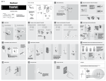
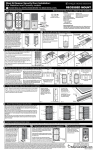
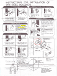
Door Preparation
If you have a new door that is not
Top view of door
pre-bored, follow these instructions.
If your door is pre-bored, proceed to
Single Cylinder or Double Cylinder
Template
Installation. The template provided
Low side of bevel
must be taped to the door as shown
Door
to mark locations for drilling holes.
Thickness
To position the template, fold the
template on line and locate on door
A
at specified height (about 40” from
B
the floor). If the door is beveled,
place the folded edge on the low
side of the bevel as shown in the
illustration. Determine the door
backset
thickness and backset
(2-3/8” or 2-3/4”). Mark the door
for face and edge bores.
Parts Enclosed:
Exploded View Single Cylinder Deadbolt
Tools Needed: Door Preparation
If your door is not pre-bored,
see Door Preparation section.
1. Pencil
2. Measuring Tape or Rule
3. 2-1/8” Diameter Hole Saw
4. 1/2” or 3/4” Wood Chisel
5. Drill and assorted bits 1/8”,
5/32” and 1”
Tools Needed: Deadbolt
Installation
1. Measuring Tape or Rule
2. One pair needle-nose pliers
3. One pair slip joint or lineman’s
pliers
4. No. 2 and No. 3 Phillips Head
Screwdrivers
5. 1/8” Allen Wrench (supplied)
6. Flat Head Screwdriver
Drill the 2-1/8” diameter face bore (A) through the door.
Drill 1” diameter edge
bore (B) 3-1/2” deep
for 2-3/8” backset, or
3-7/8” deep for 2-3/4”
backset. To ensure the
correct depth of hole B
mark your drill bit
using masking tape as
shown in the illustration.
Caution: Re-check
hole locations
before drilling.
Note: See Strike Installation section for strike parts listing.
Exploded View Double Cylinder Deadbolt
Double Cylinder Assembly
a. Carefully break off cylinder
tailpiece at required mark for your
door thickness.Caution; use two
pairs of pliers as shown or
tailpiece will be damaged.
Slot
Tailpiece
Cylinder
Note: See Strike Installation section for strike parts listing.
Parts Enclosed:
1. 1 Inside Cylinder Collar
2. 1 Cylinder Cover
3. 2 each #10 -32x2-1/4” Flat Head
Machine Screws
4. 1 Inside Cylinder
5. 1 Threaded Collar
6. 1 Adjustable Backset Deadbolt
7. 4 each #8 x 3/4” Flathead
Combination Screws
8. 1 Outside Cylinder Collar
9. 1 Outside Cylinder
10. Screw Guide
TEAR HERE FOR ENGLISH.
Break with
this plier
B
Hold with
this plier
Tailpiece
Cylinder
b. Insert deadbolt. Secure with two #8 x 3/4" flat
head combination screws provided (see diagram
for proper positioning). Ensure deadbolt head is
extended throughout installation procedure.
Install deadbolt with
both long slots on latch
body in upper position.
Rotate to
adjust
backset.
A
Face bore
Single Cylinder Assembly
a. Extend the deadbolt using a flat head
screwdriver as shown. From the outside
of the door, place the Screw Guide in the
bored hole so that it fits around the
Deadbolt. Note: The screw guide
must be mounted from the exterior
side of the door. The arrow on the
screw guide must be visible and
pointing up. Place the Collar over the
hole, and insert the Cylinder into the
Collar and Deadbolt. Note: Cylinder
tailpiece must be vertical when installing
cylinder. Hold in place while moving to
step b. Do not insert key into the
Cylinder during this procedure.
b. Align tailpiece with slot.
Keep tailpiece vertical and
curved toward right side of
the hole as illustrated.
Chisel out the area marked for the
faceplate to a depth of 5/32” or
until the faceplate is flush with
the door edge. Proceed to the
“Installing the Deadbolt” section.
Edge bore
A- 2-1/8” DIAMETER
B- 1” DIAMETER
1. 2 each #8 - 32 Oval Head Machine Screw
2. 1 Turnpiece Trim
3. 2 each #10 -32 x 1-7/8” Pan Head Machine Screw
4. 1 Turnpiece Mounting Plate
5. 1 Adjustable Backset Deadbolt
6. 4 each #8 x 3/4” Flathead Combination Screws
7. 1 Outside Cylinder Collar
8. 1 Outside Cylinder
9. Screw Guide
Insert deadbolt into edge of door.
While holding faceplate, trace the
outline of the faceplate onto the
door edge. Mark screw hole
centers and drill pilot holes with a
1/8”drill.
Installing Deadbolt
a. The deadbolt supplied with
this unit has an adjustable backset feature. When removed from
the box it will be set at 2-3/8”
backset. To adjust the deadbolt to
2-3/4” backset, grasp the body
and twist thefaceplate / bolthead
assembly 180 degrees until it
stops. The unit is now ready for
installation in 2-3/4” backset.
a. Extend the deadbolt using a flat
head screwdriver as shown. From
the outside of the door, place the
Screw Guide in the bored hole so
that it fits around the Deadbolt.
Note: The screw guide must
be mounted from the exterior
side of the door. The arrow on
the screw guide must be
visible and pointing up. Place
the Collar over the hole, and
insert the Cylinder into the Collar
and Deadbolt. Note: Cylinder
tailpiece must be vertical when
installing cylinder. Hold in place
while moving to step b. Do not
insert key into the Cylinder
during this procedure.
OUTSIDE
b. Place the Turnpiece Mounting
Plate over the bore on the inside of
the door. When positioned properly
the word “Top” will be at the 12
o’clock position and against the
door ( not visible). Insert two #1032 x 1-7/8” pan head machine
screws through the two holes in
the Mounting Plate, through the
deadbolt, and into the threaded
holes on the back side of the
Cylinder. Check that the Mounting
Plate is centered on the bore in the
door and rests flat against the
door. Tighten the screws.
b. Insert the Inside Cylinder into the
hole in the Threaded Collar. The slot in
the top of the Inside Cylinder engages
the notch in the Threaded Collar. Place
these two components into the bore on
the inside of the door so that the tailpiece from the Inside Cylinder engages
the slot in the Deadbolt. Insert two
#10-32 x 2-1/4” flat head machine
screws into the two holes on the Inside
Cylinder and tighten them down to
connect the components on the outside
of the door. Note: the tailpiece on the
cylinder must be vertical and towards
the right side of the hole during this
procedure. Do not insert the key into
OUTSIDE either cylinder during this step.
INSIDE
INSIDE
c. Place the Turnpiece
Trim over the Mounting
Plate. The turnpiece
must be horizontal as
shown in the illustration.
The cylinder tailpiece, in
the vertical position,
must slide into the turnpiece slot. Attach the
Turnpiece Trim to the
Mounting Plate with two
#8-32 x 5/8” oval head
machine screws. Tighten
the screws.
TOP VIEW
INSIDE
c. Align the cylinder cover over
the inside cylinder. Screw on the
inside cylinder collar.
OUTSIDE
CYLINDER
INSIDE
CYLINDER
TAILPIECES
MUST
MEET EACH
OTHER AS
SHOWN
TEAR HERE FOR ENGLISH.
INSIDE
2-1/8” Deadbolt Preparation
Strike Installation
Using reinforcing strike as a template, mark
locations for reinforcing screws. (fig 3) Drill
two 5/32" dia. pilot holes for the 3" long
screws and two 1/8" dia. pilot holes for the
#8 x 3/4" screws. Mark drill points 5/16"
above and below centering point. Bore two
1" dia. holes 1-1/4" deep at these points.
Chisel out holes for dust box. (fig. 4)
With your purchase of The Images Collection solid brass deadbolt, you’re among a group
of discerning individuals who know the intrinsic value of selecting the finest – Baldwin.
Images entrance locksets, interior latchsets, and deadbolts coordinate beautifully, enabling you
to carry a specific design theme throughout your home.
Our step-by-step installation instructions will help guide you through your
project quickly and easily.
Before you begin your installation, read and understand the
installation instructions and marking templates. If you have any
questions, please do not hesitate to contact our Baldwin Technical Services Department,
1-800-566-1986. We’re here to help!
NOTE: Failure to use all recommended components will void Grade 1 rating.
We thank you for your Baldwin purchase and wish you the fullest
enjoyment of your Baldwin Handleset.
fig. 4
OUTSIDE
Drill 1/8" dia. pilot holes
for # 8 screws.
Bore 1" dia. hole
above and below
centering point.
INSIDE
fig. 5
5
Install strike as illustrated.
1. Dust Box
2. Reinforcing Strike
3. #8 x 3/4" Combination Screws (2)
4. 3" Reinforcing Screws* (2)
5. Strike Plate
6. #8-32 x 1/4" Machine Screws (2)
Technical Services Support
1-800-566-1986
Hours: 8 a.m. to 8 p.m. E.S.T - Monday - Friday
10 a.m. to 6 p.m. E.S.T - Saturday
Remember Baldwin
5/16" above
center point.
Drill 5/32" dia. pilot
holes for 3" screws.
Chisel out the
area marked in
step (2) 7/32"
deep or until the
strike box,
reinforcing strike
and strike plate
fits inside mortise
and flush with
the door frame.
(fig. 5)
Congratulations!
Position strike plate on center
mark. Align and trace outside
of strike and mounting screws
onto the door frame. (fig. 2)
Complete deadbolt
installation before
installing the strike.
Install weather
stripping before
setting the strike. Close
the door and extend the
deadbolt several times
against the door frame.
The strike centering
indicator will leave a
center mark on the door
frame to aid in locating
the strike. (fig. 1)
center line
5/16" below
center point.
Logotype: Build
Tahoe 2-1/8” Collar
Auxiliary Deadbolt
consider using it on your company
INSIDE
*Note:
Lubricant recommended
when installing 3"
reinforcing screws.
Installation Instructions
With the completion of your project, remember that Baldwin quality
hardware products are available for all your decorating and remodeling needs. Matching knob and leversets for interior doors, beautiful
bath accessories, and a complete selection of cabinet and door
enhancing hardware are all available from your Baldwin retailer.
PK-1229E (08/10)
©2010 Baldwin Hardware Corporation
Lake Forest, California, 92610
TEAR HERE FOR ENGLISH.
TEAR HERE FOR ENGLISH.