1
SMA Solar Technology AG
Commissioning
6 Commissioning
#
WARNING!
Follow the steps in the commissioning procedure in the order they are presented.
Deviating from these procedures could expose you to lethal voltages that can cause
serious injury and/or death.
WARNING!
Never insert the GFDI fuse into the Sunny Boy without the fuse holder base. Latent voltage
may still be present and electric shock may result.
CAUTION!
Follow the steps in the commissioning procedure in the order they are presented.
Deviating from these procedures could cause irreversible damage to the Sunny Boy and
void the warranty.
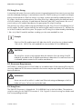
All Sunny Boy inverters have a sophisticated system for detecting and responding to PV array
ground faults as required by NEC Section 690.5. The PV array normally operates in a grounded
configuration. Depending on the type of system, the array’s negative or positive conductor is
connected to the grounding system inside the inverter as a part of the UL1741 Listed ground-fault
detection system. The GFDI protection is active whenever there is sufficient DC voltage to turn on
the LCD in the Sunny Boy.
To commission the Sunny Boy, follow these simple instructions:
1.
Make sure any covering placed over the PV array is removed.
2.
Connect the grid voltage to the Sunny Boy by switching on the main AC circuit breaker in the
main utility panel.
3.
Switch the external DC disconnect to the „on“ position or switch the SMA DC-Disconnect to
the “1“ position. If there is sufficient sunlight available, the Sunny Boy will enter the “Wait”
mode at this time and the green LED will begin to blink.
4.
If no AC faults are detected, the “Wait” mode will end after 10 seconds and the green LED
will stop blinking, remain on and the Sunny Boy will begin to operate normally. If an AC fault
was registered, the Sunny Boy will wait 5 minutes prior to starting.
76
SB50US-70US-IUS090523
Installation Guide