Download UNIVERSAL PROGRAMMABLE SCROLLING LCD
Transcript
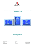
S. & A.S. LTD UNIVERSAL PROGRAMMABLE SCROLLING LCD REF. UNILCD V1.1 USER’S MANUAL FOR S/W VERSION 1.00 1514 Beirut Office: Boutros Building 1st Basement Cheikh-el-Ghabi Street Ghabi Beirut 2068 7808 Lebanon Tel: +961 1 216 994 Fax:+961 1 339 600 Headquarters & Factory: S. & A. S. Building Seaside Road Jieh Chouf Lebanon Tel: +961 7 996 333 Fax:+961 7 996 116 Website: www.sascontrollers.com Technical Support & Email: Tel: +961 71 996 333 [email protected] 2 1. GENERAL DESCRIPTION 1.1 TECHNICAL DATA .............................................................................................................................. 3 2. FUNCTION DESCRIPTION 2.1 SETTING AND ACCESSING THE MENU ........................................................................................... 3 2.2 FLOOR CONFIGURATION ................................................................................................................. 4 2.3 DISPLAY CONFIGURATION............................................................................................................... 4 2.4 FLOOR GREETING MESSAGES........................................................................................................ 5 2.5 SPECIAL MESSAGES ......................................................................................................................... 5 3. INSTALLATION AND MOUNTING 3.1 INSTALLATION ................................................................................................................................... 5 3.2 MOUNTING.......................................................................................................................................... 5 4. UNILCD DESKTOP APPLICATION 4.1 INSTALLING THE UNILCD DRIVER ................................................................................................... 5 4.2 INSTALL DESKTOP APPLICATION PROCESS ................................................................................. 5 4.3 RUNNING UNILCD DESKTOP APPLICATION................................................................................... 8 5. UNILCD MOBILE APPLICATION 5.1 INSTALLING THE UNILCD APPLICATION ...................................................................................... 12 5.2 RUNNING UNILCD MOBILE APPLICATION .................................................................................... 12 3 3 5 5 12 3 1. GENERAL DESCRIPTION The UNILCD is a universal scrolling display for the elevator floor information. It is capable of handling up to 32 floors with the possibility of editing and modifying the display contents for each floor. It has a 28x17 pixels graphic display. Three push buttons are provided to access the menu and change the display contents of each floor as well as modify the display configuration and function. Furthermore, a Desktop application and an Android application are provided to access the menu and change its contents. 1.1 TECHNICAL DATA Supply voltage Inputs Connection Dimensions Board supply: 22Vdc +15% -25% Input active voltage level is: 22Vdc for A, B, C, D and E inputs 1 0Vdc for arrows when ALo is set to Yes 1 22Vdc for arrows when ALo is set to No Screw type, plug-in connectors Screen: 83mmx49mm Case: 113mmx81mmx34mm 2. FUNCTION DESCRIPTION The content of the memory corresponding to the floor set by the gray or binary (set by Ind) inputs is displayed (GF, B1, M, 1 ....). Every change on the floor information inputs triggers the scrolling of the display to reflect the content of the newly selected floor. The scrolling direction depends on the elevator direction and on the Sdr setting. Arrows 2 are also shown on the display . 2.1 SETTING AND ACCESSING THE MENU To access the parameters menu, press the SELECT/OK push button. You will be prompted to enter a password. The password consists of 3 digits. It is provided by S. & A.S. Co. Ltd. It is referred to as client password. The first digit on the left starts blinking. Use the NEXT/DEC push button to decrement the digit and the PREV/INC push button to increment the digit. When the desired digit is reached, push the SELECT/OK push button. The digit is accepted and replaced by “*”. The next digit starts blinking. Repeat the above procedure for the remaining 2 digits. If you have entered the right password, access to the menu will be granted. Otherwise, access will be denied. Once you entered the menu, the PREV/INC and NEXT/DEC push buttons are used to scroll up and down respectively in the menu list. Pressing the SELECT/OK push button will edit the value of the parameter displayed. Use the PREV/INC or NEXT/DEC push buttons to respectively increase or decrease the value. Press the SELECT/OK push button to save new value. Following is a description of the parameters: Display FLr Cfg SMS MES MET 1 2 Description Sets the contents to be displayed for each floor. Selects the greeting messages according to the location of the UniLCD (cabin or hall) or disables greeting messages all together. For hall with wide or long selection, hall greeting message will be displayed when both arrows are inactive. For hall with double selection, hall greeting message will be displayed all the time. For cabin with wide or long selection, no hall greeting message is displayed. For cabin and double selection, hall greeting message will be displayed when one of the arrows is blinking. If the message is shorter than 39 characters, it can be ended by entering CR . Sets the delay in seconds to display the greeting message when both arrows are inactive. Applicable only for hall with wide or long selection. REFER TO SECTION 2.1 TO ACCESS ALO SETTING REFER TO SECTION 2.3 FOR MORE DETAILS Range Factory setting 0…9, blank, -, +, A…Z, a…z GF to 31 Dis, Hal, Cab Dis 39 Characters Welcome 5 to 99 10 sec 4 Display Flr MES Ctr Sdr ALo Ind LCo LCn Lng Bas Mez Flp FSt Ext Description For cabin selection, greeting message of each floor will be displayed when both arrows are inactive or one of the arrows is fixed. For each floor, a greeting message will be entered to be displayed. If the message is shorter than 39 characters, it can be ended by entering CR . Sets the display contrast. Sets the scroll direction. When Yes is selected, Up and Down arrow become active low. Selects the floor coding. Selects the character display color. Selects the display configuration. 1 Sets the special messages language . Sets the number of basements. Once the basement number is selected, the floors configuration will be updated automatically. The basements configuration will have “B#” format. Indicates the presence of one mezzanine floor. Once the mezzanine is modified the floors configuration will be updated automatically. When set to Yes, the mezzanine floor is added with “ M” configuration between GF and first floor. Flips display upside down, it is adjusted according to the viewing angle. Load factory setting. Exit menu. Range Factory setting 39 Characters Welcome 0 to 30 Dn, Up, Non 10 Dn Yes, No Yes gra, bin Whi, Blu Wid, Lng, Dbl Eng, Fre, Swe, Spa gra Whi Wid Eng 0 to 9 0 Yes, No No Yes, No No - - 2.2 FLOOR CONFIGURATION The memory content of each floor can be modified by following the steps below: 1. Make sure that the display is powered; it should show the memory content of the currently selected floor. 2. Enter the menu and select FLr CFg, to change the configurations of the floors 3. The display will show the first floor number on line 1. The corresponding memory content is shown on the second line. 4. Use the NEXT/DEC or PREV/INC push button to scroll to the desired floor. 5. Press the SELECT/OK push button. The leftmost character of the memory content of this floor starts blinking 6. Use the NEXT/DEC or PREV/INC push button to scroll to the desired leftmost character (0…9, blank, -, +, A…Z, a…z) 7. Press the SELECT/OK to save the leftmost character content. The rightmost character starts blinking. 8. Use the NEXT/DEC or PREV/INC push button to scroll to the desired rightmost character (0…9, blank, -, +, A…Z, a…z) 9. Press the SELECT/OK to save the rightmost character content. 10. To exit the floor configuration, scroll to F00 and Press NEXT/DEC or scroll to F31 and Press PREV/INC to show FLr CFg page. 2.3 DISPLAY CONFIGURATION The character display color can be white or blue. Selection is done by LCo. The display has 3 configurations: 1. Horizontal wide: Selection by setting LCn to Wid. The display is mounted horizontally and uses the full screen to show the floor information in big characters. Arrows are shown on the side. When a greeting message is displayed the screen will be splitted into two horizontal lines. 2. Vertical: Selection by setting LCn to Lng. The display is mounted vertically and uses the full screen to show the floor information in big characters. Arrows are shown on top and bottom. 1 REFER TO SECTION 2.5 FOR MORE DETAILS 5 3. Horizontal with 2 lines: Selection by setting LCn to Dbl. The display is mounted horizontally. It uses first line to show the floor information. The second line is used for the greeting messages. Arrows are shown on the side of first line. The display can be flipped upside down according to the viewing angle. Selection is done by Flp. To elaborate, for Wid and Dbl, flip should be set to Yes for eye level or lower mounting. Moreover, for Lng configuration, flip should be set to Yes for right hand side mounting. 2.4 FLOOR GREETING MESSAGES The greeting message content of each floor can be modified by following the steps below: 1. Make sure that the display is powered; it should show the memory content of the currently selected floor. 2. Enter the menu and select FLr MES to change the content of the greeting message of each floor. 3. The display will show the first floor number on line 1. The corresponding greeting message content is shown on the second line. 4. Use the NEXT/DEC or PREV/INC push button to scroll to the desired floor. 5. Press the SELECT/OK push button. The first character of the greeting message of this floor starts blinking. 6. Use the NEXT/DEC or PREV/INC push button to scroll to the desired character. 7. Press the SELECT/OK to save the first character content. The second character starts blinking. 8. Repeat the same procedure to enter the whole floor message. 9. is entered to end the greeting message. 10. To exit the floor messages, scroll to F00 and Press NEXT/DEC or scroll to F31 and Press PREV/INC to show FLr MES page. 2.5 SPECIAL MESSAGES When a S. & A.S. controller is connected to UNILCD and the display type is set to “enhanced”, six different special messages will be displayed according to the lift status. The language of these messages is selected by Lng: 1. 2. 3. 4. English (Wait, Maintenance, out of service, call maintenance, evacuation, over load). French (Attendre, Revision, Hors service, Appeler service, Evacuation, Charge max). Swedish (Vänta, Service, Out of service, Call maintenance, evacuation, overlast). Spanish (Espere un momento, En mantenimiento, Fuera de servicio, Llamar a mantenimiento, evacuacion, Sobrecarga). 3. INSTALLATION AND MOUNTING 3.1 INSTALLATION Connect terminals P and GND to power supply. Connect terminals A, B, C, D and E of the UNILCD board directly to A, B, C, D and E of the controller board. Connect terminals UP and DOWN of the UNILCD board directly to UP and DOWN arrow of the controller board. 3.2 MOUNTING Mounting plate thickness: 0.8mm to 5mm. Cutout in mounting plate: 111mmx71mm. No need for welded studs (screws). 4. UNILCD DESKTOP APPLICATION 4.1 INSTALLING THE UNILCD DRIVER In order to install the application on a computer, a CD is provided by S.&A.S.Ltd and the below steps shall be followed: 1. Run file “SAS_Patch.exe” located in “UniLCDDriver” folder. 2. Plug in the USB cable to the UniLCD device before turning power on. 3. Turn on the UniLCD device. 4.2 INSTALL DESKTOP APPLICATION PROCESS 1. Run “UniLCD_windows_1_1” application. 2. Click next to continue the installation. 6 3. Choose the destination directory of the application. 7 4. Select the folder where the shortcut will be created. 5. The UniLCD Application is installed successfully. 8 4.3 RUNNING UNILCD DESKTOP APPLICATION 1. Run the application 2. Plug-in your UniLCD. There is a beep signaling that your PC has detected your device. Click on the refresh button. Your device name along with the com port number will appear in the box. 3. Click on your device name. Enter your UniLCD password. Press ok button to start accessing the UniLCD settings. 9 If your password is correct the UniLCD parameters tab will open. 10 Below is the parameters table: 11 Floor configuration and greeting messages can be seen and modified. Control panel buttons : 1. Update: To download the displayed parameters on the UniLCD. 2. Load from file: Load parameters from file to display. 3. Save to file: Save the displayed parameters in a file. 4. Refresh: Reload parameters from UniLCD. 5. Factory Reset: Display the factory settings. 12 5. UNILCD MOBILE APPLICATION 5.1 INSTALLING THE UNILCD APPLICATION In order to install the application on the mobile, you have to: 1. 2. 3. 4. Run the “Play store” in your mobile. Search for the “Unilcd” application. Accept the permissions. Install the application. 5.2 RUNNING UNILCD MOBILE APPLICATION 1. 2. 3. 4. Run the UNILCD application. Connect your UniLCD to the mobile and start your settings configuration. A beep signals that your mobile has detected the device. A pop up window appears. When checked, the UniLCD application will be opened whenever a USB device is connected. 13 5. Enter the UniLCD password (000). 6. Press “Submit” button to enter the parameters menu. Several tabs will appear showing all the parameters: 14 Control panel buttons : 1. Update: To download the displayed parameters on the UniLCD. 2. Import: Load parameters from file to display. 3. Export: Save the displayed parameters in a file. 4. Refresh: Reload parameters from UniLCD. 5. Factory Reset: Display the factory settings. 15


