1
QUADRAPADDLE INSERT USER’S MANUAL
TABLE OF CONTENTS
SECTION 1 QUADRAPADDLE INSERT PART IDENTIFICATION
SECTION 2 QUADRAPADDLE INSERT INSTALLATION/REMOVAL INSTRUCTIONS
SECTION 3 QUADRAPADDLE INSERT CONTACT INSTALLATION/REMOVAL INSTRUCTIONS
SECTION 4 RAILS INSTALLATION/REMOVAL INSTRUCTIONS
Please note that any printed or downloaded User Manuals or Procedure Sheets may not reflect the
most current revisions. The information contained in these materials is subject to change.
For the most current information available, visit www.vpc.com.
7/30/15
VIRGINIA PANEL CORPORATION
QUADRAPADDLE INSERT USER’S MANUAL: SECTION 1
QUADRAPADDLE RECEIVER INSERT PART IDENTIFICATION
PART # 510 180 101
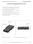
This section will point out features designed to help determine the proper orientation
of the QuadraPaddle receiver Insert (Figure A), as well as distinguishing features.
The top of the QuadraPaddle receiver Insert can be determined by the position 1
indicator, designated by the triangle shown in Figure A.
The front and rear of the QuadraPaddle receiver Insert are shown in Figure B. The
front side mates with the QuadraPaddle ITA Insert.
The rear of the QuadraPaddle receiver Insert has the position1 indicator located on
the top. Wires exit the QuadraPaddle receiver Insert from the rear side.
The Insert is keyed like the VTAC HSD Insert to ensure proper orientation (see VTAC
User’s Manual Section 2-1 Figure C).
POSITION 1 TRIANGLE
INDICATOR
POSITION 1 TRIANGLE
INDICATOR
CONTACT RETENTION/
EXTRACTION CAVITY
TOP
REAR
WIRING
SIDE
FRONT
MATING
SIDE
BOTTOM
Figure A. QuadraPaddle receiver Insert.
1-1
Figure B. QuadraPaddle receiver Insert (side view)
For the most current information available, visit www.vpc.com
7/30/15
VIRGINIA PANEL CORPORATION
QUADRAPADDLE INSERT USER’S MANUAL: SECTION 1
QUADRAPADDLE ITA INSERT PART IDENTIFICATION
PART # 510 181 101
This section will point out features designed to help determine the proper orientation
of the QuadraPaddle ITA Insert (Figure A), as well as distinguishing features.
The top of the QuadraPaddle ITA Insert can be determined by the position 1
indicator, designated by the triangle shown in Figure A.
The front and rear of the QuadraPaddle ITA Insert are shown in Figure B. The front side
mates with the QuadraPaddle receiver Insert.
The rear of the QuadraPaddle ITA Insert has the position1 indicator located on the
top. Wires exit the QuadraPaddle ITA Insert from the rear side.
The insert is keyed like the VTAC HSD Insert to ensure proper orientation (see VTAC
User’s Manual Section 2-1 Figure C).
POSITION 1 TRIANGLE
INDICATOR
POSITION 1 TRIANGLE
INDICATOR
TOP
REAR
WIRING
SIDE
FRONT
MATING
SIDE
BOTTOM
Figure A. QuadraPaddle ITA Insert.
1-2
Figure B. QuadraPaddle ITA Insert (side view)
For the most current information available, visit www.vpc.com
7/30/15
VIRGINIA PANEL CORPORATION
QUADRAPADDLE INSERT USER’S MANUAL: SECTION 2
INSERT INSTALLATION/REMOVAL INSTRUCTIONS FOR RECEIVER MODULE
PART # 510 170 101
TOOLS REQUIRED
VTAC Extraction Tool Kit, Receiver and ITA, Part # 910 112 130
INSERT INSTALLATION INSTRUCTIONS
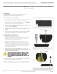
1. Ensure that the Insert(s) is in-line with the corresponding
VTAC HSD INSERT
BLUE INSERT
module location. Apply gentle pressure and insert the Insert(s)
into the rear (wiring side) of the module shown in Figure A. The
Insert(s) can only go into one side. Once in place, gently pull
the wire to ensure the Insert(s) is fully seated.
INSERT REMOVAL INSTRUCTIONS
1.
Group the required number of extraction tools together for
the given patchcord shown in Figure B. The tool pins should be
on the mating side of the module.
QUADRAPADDLE INSERT
WARNING: All Inserts within each patchcord must be extracted
simultaneously to prevent damage to Inserts.
NOTE: The extraction tools are magnetic to aid in stacking them
together.
2.
While grasping the extraction tool(s) body from the sides
(Figure B), slide tool pins into module’s extraction cavity
square holes until the tool frame is seated against the body
shown in Figure C.
WARNING: The extraction tool(s) need to be seated against
the module front face before the plunger is pushed in. Otherwise
damage to Insert(s) may occur.
3.
Figure A. Insert installation.
Push plunger of extraction tool(s) in to extract Insert(s). The
Insert(s) will be ejected out the wiring side of the module
shown in Figure D.
PLUNGER
GRIP
SEAT
PUSH
PLUNGER
DETAIL A
EXTRACTION TOOL
PINS
Figure B. Insert removal tool pins.
2-1
Figure C. Seat removal tool
to module frame.
Figure D. Push removal tool plunger.
For the most current information available, visit www.vpc.com
7/30/15
VIRGINIA PANEL CORPORATION
QUADRAPADDLE INSERT USER’S MANUAL: SECTION 2
INSERT INSTALLATION/REMOVAL INSTRUCTIONS FOR ITA MODULE
PART # 510 171 101
TOOLS REQUIRED
VTAC Extraction Tool Kit, Receiver and ITA, Part # 910 112 130
VTAC HSD INSERT
BLUE INSERT
INSERT INSTALLATION INSTRUCTIONS
1. Ensure that the Insert(s) is squared up with the corresponding
module location. Apply gentle pressure and insert the Insert(s)
into the rear (wiring side) of the module shown in Figure A. The
Insert(s) can only go into one side. Once in place, gently pull the
wire to ensure the Insert(s) is fully seated.
HSD INSERT REMOVAL INSTRUCTIONS
1.
Group the required number of extraction tools together for the
given patchcord shown in Figure B. The tool pins should be on
opposite sides of the patchcords or wires to be removed.
QUADRAPADDLE INSERT
WARNING: All Inserts within each patchcord must be extracted
simultaneously to prevent damage to Inserts.
NOTE: The extraction tools are magnetic to aid in stacking them
together.
2.
While grasping the extraction tool(s) body from the sides,
(Figure B), slide tool pins into module’s extraction cavity slots until
the tool frame is seated against the body shown in Figure C.
Figure A. Insert installation.
WARNING: The extraction tool(s) need to be seated against the
module front face before the plunger is pushed in. Otherwise
damage to Insert(s) may occur.
3.
PLUNGER
GRIP
Push plunger of extraction tool(s) in to extract Insert(s). The
Insert(s) will be ejected out the wiring side of the module shown in
Figure D.
DETAIL A
EXTRACTION TOOL
PINS
Figure B. Insert removal tool pins.
SEAT
PUSH
PLUNGER
Figure C. Seat removal tool to module frame.
2-2
Figure D. Push removal tool plunger.
For the most current information available, visit www.vpc.com
7/30/15
VIRGINIA PANEL CORPORATION
QUADRAPADDLE INSERT USER’S MANUAL: SECTION 2
INSERT INSTALLATION/REMOVAL INSTRUCTIONS FOR i2 MX RECEIVER
PART # 310 130 XXX
TOOLS REQUIRED
VTAC Extraction Tool Kit, Receiver and ITA, Part # 910 112 130
INSERT INSTALLATION INSTRUCTIONS
1. Ensure that the Insert(s) is squared up with the corresponding module
location. Apply gentle pressure and insert the Insert(s) into the rear
(wiring side) of the module shown in Figure A. The Insert(s) can only
go into one side. Once in place, gently pull the wire to ensure the
Insert(s) is fully seated.
VTAC HSD INSERT
BLUE INSERT
INSERT REMOVAL INSTRUCTIONS
1.
Group the required number of extraction tools together for the given
patchcord shown in Figure B. The tool pins should be on opposite
sides of the patchcords or wires to be removed.
QUADRAPADDLE INSERT
WARNING: All Inserts within each patchcord must be extracted
simultaneously to prevent damage to Inserts.
NOTE: The extraction tools are magnetic to aid in stacking them together.
2.
While grasping the extraction tool(s) body from the sides (Figure B).
slide tool pins into module’s extraction cavity slots until the tool frame
is seated against the body shown in Figure C.
3.
Push plunger of extraction tool(s) in to extract Insert(s). The Insert(s) will
be ejected out the wiring side of the module shown in Figure D.
Figure A. Insert installation
WARNING: The extraction tool(s) need to be seated against
the module front face before the plunger is pushed in.
Otherwise damage to Insert(s) may occur.
GRIP
PUSH
PLUNGER
Figure B. Insert Removal.
SEAT
PLUNGER
Figure C. Seat Removal tool
2-3
Figure D. Push removal tool plunger.
For the most current information available, visit www.vpc.com
7/30/15
VIRGINIA PANEL CORPORATION
QUADRAPADDLE INSERT USER’S MANUAL: SECTION 2
INSERT INSTALLATION/REMOVAL INSTRUCTIONS FOR i2 MX ITA
PART # 410 130 XXX
TOOLS REQUIRED
VTAC Extraction Tool Kit, Receiver and ITA, Part # 910 112 130
BLUE INSERT
INSERT INSTALLATION INSTRUCTIONS
1. Ensure that the Insert(s) is squared up with the
corresponding module location. Apply gentle pressure
and insert the Insert(s) into the rear (wiring side) of the
module shown in Figure A. The Insert(s) can only go into
one side. Once in place, gently pull the wire to ensure
the Insert(s) is fully seated.
VTAC HSD INSERT
NOTE: Backshell removal instructions start in Section 2-5.
NOTE: For i2 MX ITA Cable Assembly and Backshell Installation
Instructions, refer to the i2 MX User’s manual Section 5.
QUADRAPADDLE INSERT
Figure A. Insert installation
2-4
For the most current information available, visit www.vpc.com
7/30/15
VIRGINIA PANEL CORPORATION
QUADRAPADDLE INSERT USER’S MANUAL: SECTION 2
INSERT REMOVAL INSTRUCTIONS FOR i2 MX ITA
PART # 410 130 XXX
TOOLS REQUIRED
Phillips Head Screwdriver
Flat Head Screwdriver
1/4” Nut Driver, hollow shaft
VTAC Extraction Tool Kit, Receiver and ITA, Part # 910 112 130
KNOB
REMOVAL INSTRUCTIONS
1.
Disengage the ITA from the receiver.
2.
Using a flat head screwdriver, remove the engagement
knob screw and engagement knob (Figure A).
3.
Using a Phillips head screwdriver, loosen the four screws
(captive) that secure the backshell to the ITA frame
(Figure B).
KNOB SCREW
Figure A. ITA knob removal.
FRAME TO
BACKSHELL
SCREWS
Figure B. Remove frame to backshell screws.
2-5
For the most current information available, visit www.vpc.com
7/30/15
QUADRAPADDLE INSERT USER’S MANUAL: SECTION 2
VIRGINIA PANEL CORPORATION
INSERT REMOVAL INSTRUCTIONS FOR i2 MX ITA
PART # 410 130 XXX
REMOVAL INSTRUCTIONS (CONTINUED)
4.
Using a Phillips head screwdriver, loosen the six screws
(captive) that secure the backshell halves. Remove the
half with the screws (Figure C).
5.
Using a nut driver remove nuts on the strain relief clamp,
then remove the clamp (Figure D).
BACKSHELL
SCREWS
Figure C. Backshell cover removal.
NUT
STRAIN RELIEF
CLAMP
Figure D. Strain relief clamp removal.
2-6
For the most current information available, visit www.vpc.com
7/30/15
QUADRAPADDLE INSERT USER’S MANUAL: SECTION 2
VIRGINIA PANEL CORPORATION
INSERT REMOVAL INSTRUCTIONS FOR i2 MX ITA
PART # 410 130 XXX
INSERT REMOVAL INSTRUCTIONS (CONTINUED)
1.
Group the required number of extraction tools
together for the given patchcord shown in
Figure E. The tool pins should be on opposite sides of
the patchcords or wires to be removed.
SEATED
FLUSH
WARNING: All Inserts within each patchcord must be
extracted simultaneously to prevent damage to Inserts.
NOTE: The extraction tools are magnetic to aid in stacking
them together.
2.
GRIP
While grasping the extraction tool(s) body from the
sides (Figure E), slide tool pins into module’s extraction
cavity slots until the tool plunger is flush with the tool
body and the plunger is in contact with the Insert tips
shown in Figure E.
WARNING: The extraction tool(s) need to be seated against
the module front face before the plunger is pushed in.
Otherwise damage to Insert(s) may occur.
3.
PLUNGER
Push plunger of extraction tool(s) in to extract Insert(s).
The Insert(s) will be ejected out the wiring side of the
module shown in Figure F.
PLUNGER
Figure E. Seat removal tool.
PUSH
PLUNGER
PUSH
PLUNGER
Figure F. Insert removal.
2-7
For the most current information available, visit www.vpc.com
7/30/15
VIRGINIA PANEL CORPORATION
QUADRAPADDLE INSERT USER’S MANUAL: SECTION 3
QUADRAPADDLE INSERT CONTACT INSTALLATION/REMOVAL INSTRUCTIONS
TOOLS REQUIRED
Tool, Module Insert, QuadraPaddle, Receiver, Part # 910 112 131
Tool, Extraction, QuadraPaddle, ITA Part # 910 110 111
CONTACT REMOVAL INSTRUCTIONS (RECEIVER)
1.
Remove QuadraPaddle Insert from receiver frame
(see Section 2-1 and 2-3)
2.
Align extraction tool protrusions to extraction cavity
(see Figure B and C).
3.
Apply pressure to QuadraPaddle contact tabs (see Figure A).
4.
Remove patchcord from wiring side (see Figure C).
QUADRAPADDLE CONTACT TABS
CONTACT REMOVAL INSTRUCTIONS (ITA)
NOTE: ITA QuadraPaddle contacts can be extracted while the
QuadraPaddle Insert is in the ITA frame or after the patchcord(s) has
been removed.
NOTE: Install/Extract ITA QuadraPaddle contacts per the
QuadraPaddle User’s Manual. Reference contact Part # 610 138
109 or 610 138 112.
Figure A. QuadraPaddle receiver Insert contact removal.
APPLY PRESSURE
APPLY PRESSURE
CONTACT RETENTION/
EXTRACTION CAVITY
EXTRACTION TOOL
PROTRUSIONS
PULL
Figure B. QuadraPaddle receiver Insert contact removal tool.
3-1
Figure C. QuadraPaddle receiver Insert contact removal tool.
For the most current information available, visit www.vpc.com
7/30/15
VIRGINIA PANEL CORPORATION
QUADRAPADDLE INSERT USER’S MANUAL: SECTION 4
RAIL(S) INSTALLATION/REMOVAL INSTRUCTIONS
PART # 310 130 XXX AND 410 130 XXX
TOOLS REQUIRED
Phillips Head Screwdriver
RAIL(S) REMOVAL INSTRUCTIONS
1.
If working with a receiver, use a Phillips head screwdriver to
remove strain relief by removing screws (Figure A).
The ITA will require removal of backshell first. See Section 2 of this
User’s Manual for instructions.
2.
After removing strain relief/backshell, use a Phillips head
screwdriver to remove the two Phillips flat head screws that are
holding the frame halves together (Figure A).
For ITA use Phillips head screwdriver to loosen the two captive
screws on the back of the rear frame (Figure B).
3.
Pull halves apart.
4.
Remove Rail(s).
PHILLIPS
FLAT HEAD
SCREWS (2)
RAIL(S) INSTALLATION INSTRUCTIONS
1.
2.
To install Rail(s), orient rail(s) as shown in (Figure A).
Figure C illustrates the identifiers to aid in orientation (receiver rails
shown). The receiver rails are marked with ‘RR’ (receiver right)
and ‘RL’ (receiver left) when viewing from mating face. The ITA
rails are marked with ‘IR’ (ITA right) and ‘IL’ (ITA left) when viewing
from rear/wiring side.
TOP OF
RAIL
Place rail(s) ledge on flat surface shown in (Figure D), then put
halves together and tighten the two Phillips flat head screws using
a Phillips head screwdriver.
NOTE: Receiver/ITA frame halves are keyed to be placed together
only one direction.
PHILLIPS
CAPTIVE
SCREWS (2)
Figure A. Rail(s) install/removal (receiver shown).
BLACK POSITION
AI INDICATOR
‘RL’ RECEIVER
LEFT
‘RR’ RECEIVER
RIGHT
TOP
FLAT SURFACE
BOTTOM
Figure B. ITA frame separation.
4-1
Figure C. Rail(s) - Identifiers.
Figure D. Rail(s) install/removal (receiver
shown).
For the most current information available, visit www.vpc.com
7/30/15