1
VIRGINIA PANEL CORPORATION
QUADRAPADDLE INSERT USER’S MANUAL: SECTION 4
RAIL(S) INSTALLATION/REMOVAL INSTRUCTIONS
PART # 310 130 XXX AND 410 130 XXX
TOOLS REQUIRED
Phillips Head Screwdriver
RAIL(S) REMOVAL INSTRUCTIONS
1.
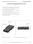
If working with a receiver, use a Phillips head screwdriver to
remove strain relief by removing screws (Figure A).
The ITA will require removal of backshell first. See Section 2 of this
User’s Manual for instructions.
2.
After removing strain relief/backshell, use a Phillips head
screwdriver to remove the two Phillips flat head screws that are
holding the frame halves together (Figure A).
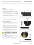
For ITA use Phillips head screwdriver to loosen the two captive
screws on the back of the rear frame (Figure B).
3.
Pull halves apart.
4.
Remove Rail(s).
PHILLIPS
FLAT HEAD
SCREWS (2)
RAIL(S) INSTALLATION INSTRUCTIONS
1.
2.
To install Rail(s), orient rail(s) as shown in (Figure A).
Figure C illustrates the identifiers to aid in orientation (receiver rails
shown). The receiver rails are marked with ‘RR’ (receiver right)
and ‘RL’ (receiver left) when viewing from mating face. The ITA
rails are marked with ‘IR’ (ITA right) and ‘IL’ (ITA left) when viewing
from rear/wiring side.
TOP OF
RAIL
Place rail(s) ledge on flat surface shown in (Figure D), then put
halves together and tighten the two Phillips flat head screws using
a Phillips head screwdriver.
NOTE: Receiver/ITA frame halves are keyed to be placed together
only one direction.
PHILLIPS
CAPTIVE
SCREWS (2)
Figure A. Rail(s) install/removal (receiver shown).
BLACK POSITION
AI INDICATOR
‘RL’ RECEIVER
LEFT
‘RR’ RECEIVER
RIGHT
TOP
FLAT SURFACE
BOTTOM
Figure B. ITA frame separation.
4-1
Figure C. Rail(s) - Identifiers.
Figure D. Rail(s) install/removal (receiver
shown).
For the most current information available, visit www.vpc.com
7/30/15