1
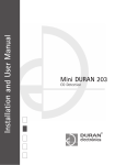
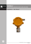
STANDGAS HC & HC PRO STAND-ALONE DETECTORS FOR EXPLOSIVE GASES Installation & User Manual Certificate nº FS82426 © 2011 DURAN ELECTRONICA S.L. - All rights reserved · www.duranelectronica.com I-manSTANDGASexp-v02 TABLE OF CONTENTS pages 1. PRESENTATION . . . . . . . . . . . . . . . . . . . . . . . . . . . . . . . . . . . . . . . . . . . . . . . . . . . . . . . . . . . . 5 2. RELAY MODULE . . . . . . . . . . . . . . . . . . . . . . . . . . . . . . . . . . . . . . . . . . . . . . . . . . . . . . . . . . . 6 3. CONNECTIONS. . . . . . . . . . . . . . . . . . . . . . . . . . . . . . . . . . . . . . . . . . . . . . . . . . . . . . . . . . . . . 6 4. PROGRAMMING AND GAS GROUP SELECTION . . . . . . . . . . . . . . . . . . . . . . . . . . . . . . . . . . . . 7 5. EXTERNAL OPTICAL INDICATIONS: messages & functioning. . . . . . . . . . . . . . . . . . . . . . . . . . . 9 6. TEST & RECALIBRATION. . . . . . . . . . . . . . . . . . . . . . . . . . . . . . . . . . . . . . . . . . . . . . . . . . . . . . 9 7. TECHNICAL CHARACTERISTICS. . . . . . . . . . . . . . . . . . . . . . . . . . . . . . . . . . . . . . . . . . . . . . . . . 10 8 GUARANTEE . . . . . . . . . . . . . . . . . . . . . . . . . . . . . . . . . . . . . . . . . . . . . . . . . . . . . . . . . . . . . . 10 I-manSTANDGASexp-v02 3 4 © 2011 DURAN ELECTRONICA S.L. All rights reserved · www.duranelectronica.com 1. PRESENTATION STANDGAS HC & HC PRO are stand-alone detectors for explosive gases using catalytic technology (pellistor) for a detection range from 0 to 100% LEL. Silicon vapours resistant sensors (HDMS) Available formats and gases STANDGAS HC Available for natural gas-methane, butane-propane, and hydrogen. STANDGAS HC PRO Available for natural gas-methane, hydrogen, butane, propane, heptane, hexane, pentane, methanol,styrene, ethane, ethanol, ethylene, propylene, acetone, ammonia, acetylene, cyclo-hexane, cyclo-pentane, dioxane, butyl acetate, ethyl acetate,acetic acid, iso-butyl alcohol, iso-propyl alcohol, decane, benzene, octane, methyl ethyl ketone, nonane, propanol, toluene, xylene. Other gases, consult. Other features • Optical indications for sensor fault. • Programmable alarm relay. • Selection of gas to detec using a jumper. • Silicon vapours resistant sensors (HDMS). Do not use these detectors in environments where there might be presence of hydrogen sulphide, fluorine, methyl chloride, trichloroethylene, sulphur dioxide, silicon vapours or sulphuric acid: the presence of these gases could either inhibit sensor’s response or damage it. I-manSTANDGASexp-v02 5 2. RELAY MODULE FUNCTIONING The stand-alone detectors STANDGAS HC and STANDGAS HC PRO are provided of a relay output with the following parameters: SW1 1 2 3 4 1 ON position Activated Instantaneous 5min. retard Alarm 20% L.E.L. OFF position Deactivated Retarded 15m retard Alarm 50% L.E.L. Programming Initial status: Idle mode relay1 Relay disconnection type2 Relay disconnection retard3 Relay alarm activation level4 Idle mode relay. It allows to select an activated relay without alarm, or a deactivated relay. Relay disconnection type. It allows to select the instantaneous disconnection of the relay once alarm condition is over or if retard selected is used. 2 Relay disconnection retard. It allows to select a retard or the instantaneous disconnection since the level selected has disappeared as an alarm condition. It has no effect if INSTANTANEOUS was previously selected. 3 4 Relay alarm activation level. It allows to select, in between two, the relay actuation level, local and independently. PROGRAMMING DEFAULT: Activated, instantaneous –no retard20% LEL alarm 3. CONNECTIONS 6 © 2011 DURAN ELECTRONICA S.L. All rights reserved · www.duranelectronica.com 4. PROGRAMMING AND GAS GROUP SELECTION STANDGAS HC & HC PRO detectors are provided with a microprocessor for functioning control. This is a great advantage due that, through software and adequate algorithms, these detectors can be reprogrammed at installation for autocalibration and sensitivity auto-adjust without using gas. In addition, it allows selecting among an extensive list of gases without ordering new detectors or storing detectors calibrated for different gases. Remove JP3 located at the vertical module with the detector powered. Watch carefully the external LED blinking (see table 1 below). When the number of LED blinking fits in with the gas group to be detected, place JP3 jumper again and watch that the corresponding LED confirms its memorized group position by the number of blinkings. Note: If JP3 is removed and after 90s no group has been chosen, the last memorized group will be automatically chosen. Default programming is GR1. Table 1 GR1 R 1 Blink GR2 RR 2 Blink GR3 RRR 3 Blink GR4 RRRR 4 Blink GR5 RRRRR 5 Blink STANDGAS HC Group Gas Relative response Methane 1 Hydrogen 30 cm from ceiling 100% Natural gas 2 Butane Propane Installation height 30 cm from ceiling 30 cm from ceiling 55% 30 cm from floor 100 cm from floor 5 5 I-manSTANDGASexp-v02 7 STANDGAS HC PRO Group Gas Relative response Methane 1 2 3 4 5 8 © 2011 DURAN ELECTRONICA S.L. All rights reserved · www.duranelectronica.com Hydrogen Installation height 30 cm from ceiling 100% 30 cm from ceiling Methanol 100 cm from floor Ethane 100 cm from floor Ethanol 100 cm from floor Ethylene 75% 100 cm from floor Propane 30 cm from floor Propylene 30 cm from floor Acetone 30 cm from floor Ammonia 30 cm from floor Cyclo-Hexane 30 cm from floor Cyclo-Pentane 30 cm from floor Dioxane 30 cm from floor Ethyl Acetate 30 cm from floor Iso-Propyl Alcohol (IPA) 55% 30 cm from floor Methyl Ethyl Ketone (MEK) 30 cm from floor Butane 30 cm from floor Hexane 30 cm from floor Pentane 30 cm from floor Propanol 30 cm from floor Propyl Alcohol 30 cm from floor Butyl Acetate 30 cm from floor Iso-Octane 30 cm from floor Heptane Toluene 42% 30 cm from floor 30 cm from floor Xylene 30 cm from floor Benzene 30 cm from floor Acetic Acid 30 cm from floor Decane 30 cm from floor Iso-Butyl Alcohol Nonane 25% 30 cm from floor 30 cm from floor Styrene 30 cm from floor Iso-Butyl Methyl Ketone 30 cm from floor 5 5 4 4 4 4 6 6 6 6 6 6 6 6 6 6 6 6 6 6 6 6 6 6 6 6 6 6 6 6 6 6 6 5. EXTERNAL OPTICAL INDICATIONS: messages & functioning These detectors are provided with a LED to indicate the following states: • Switch off: Detector without tension. • Periodical blink: Periodicity will correspond to the assigned number of the selected detection group. • 6 blinking burst: Alarm state -activated relay -. • 1s interval ON/OFF: Sensor fault. 6. TEST & RECALIBRATION All detectors manufactured by DURAN ELECTRONICA have been calibrated at factory with target gas. Therefore, it is neither required, nor recommendable recalibration once installed. ZERO OUTPUT VERIFYING Before proceeding the detector should be operating for 1 hour minimum in a clean ambient, being sure that there are no presence of gases affecting to the detector. In case this condition is not fulfilled, the detector must be subjected to a concentration of pure nitrogen with a 0.5l/min flow for 2 minutes minimum using the optional CECALIBR adaptor. Then proceed as indicated next: 1. Connect a measuring instrument between S+ and S- terminals, and thus tension must be 000V DC. If it is necessary, make an adjustment with the ZERO potentiometer until obtaining that measurement. CALIBRATION WITH GAS 1. Set the detector for Group 1, as it is described on page 7 (STANDGAS HC) and 8 (STANDGAS HC PRO). 2. Insert CECALIBR adapter into the detector and release a precise mixture of methane, at 2,5% v/v, equivalent to 50% LEL, with a 0,5l/min flow and adjust the GAIN potentiometer until the measuring instrument indicates 1.0V DC between TP+ and TP- terminals. 3. Afterwards, do not forget to reprogram the detector again for the required gas group, as described on page 7 (STANDGAS HC) and 8 (STANDGAS HC PRO). I-manSTANDGASexp-v02 9 7. TECHNICAL CHARACTERISTICS STANDGAS HC STANDGAS HC PRO Technology Catalytic sensor and microprocessor Catalytic sensor and microprocessor Power supply 10V to 30V DC (2 wires +/- ) 10V to 30V DC (2 wires +/- ) Max. consumption 130mA to 12V DC with relay activated 110mA to 12V DC with relay activated Loop max. resistance 250Ω 250Ω Max current output 21.3 mA (Tip) 21.3 mA (Tip) Fault loop current < 2mA < 2mA Exp gases measurement range 0-100% LEL (5% methane), linear in full scale 0-100% LEL (5% methane), linear in full scale Resolution ±1% L.E.L. of the measuring range ±1% L.E.L. of the measuring range Zero deviation ± 10mV/year ± 7mV/year Span deviation ± 10% L.E.L year ± 9% L.E.L year Stabilization time < 15 minutes -all specifications- < 15 minutes -all specifications- H2S resistance Yes (tipical 1000ppm/hour) Yes (tipical 1000ppm/hour) Response time T50/T90 6s / 10s resp. 3s / 8s resp Useful life (MTBF) 4 years approximately 4 years approximately Maintenance period Annual – recommended- Annual – recommended- Temperature range -10ºC to +50ºC -10ºC to +50ºC Humidity range 0 to 95% HR without condensation 0 to 95% HR without condensation Atmospheric pressure limit 80 to 110 kPa (0.8 to 1.1 bar) 80 to 110 kPa (0.8 to 1.1 bar) Fault sensor optical indications External External Status optical indications External External Relay programmable alarm 1 programmable relay output module in between 2 levels (20% LEL / 50% LEL), instant/retarded disconnection, retard disconnection programming and initial relay idle state/activated. 1 programmable relay output module in between 2 levels (20% LEL / 50% LEL), instant/retarded disconnection, retard disconnection programming and initial relay idle state/activated Coverage area 16 m2 approx. 16 m2 approx. Protection grade IP65 IP65 Box material Makrolon & ABS Makrolon & ABS Cable Diameter 6-10mm2 -for maintenance IP65- 6-10mm2 -for maintenance IP65- Dimensions (mm) & weight (gr) IP65 120x160x60 / 288 120x160x60 / 288 8. GUARANTEE STANDGAS detectors are guaranteed against any manufacturing defect for a 1 year period after the acquisition of the equipment. If, during this period of time, any abnormality were detected, please inform your provider or installer. Guarantee covers the full repair of the equipment which the DURAN ELECTRONICA Technical Department considers to be defective, with the purpose of bringing them back to their normal use. This warranty will be valid always when the equipment has been installed by a competent person, and always following the specifications contained in this manual. Its negligent installation or use will exempt DURAN ELECTRONICA from any responsibility on the damages caused to objects and/or people, and the fulfillment of the terms of this warranty. Guarantee does not include: installations, periodical tests and maintenances, damages caused by inadequate handling, inappropriate use, negligence, inadequate power or equipment abandonment, tension deviations, defective installations and other external causes, repairs or amendments made by non authorized personnel by DURAN ELECTRONICA, transportation costs of the equipments. DURAN ELECTRONICA reserves the right to modify this manual without prior notice. 10 © 2011 DURAN ELECTRONICA S.L. All rights reserved · www.duranelectronica.com I-manSTANDGASexp-v02 11 Certificado nº FS82426 c/ Tomás Bretón, 50 28045 MADRID, España Tel: +34 91 528 93 75 Fax +34 91 527 58 19 [email protected] www.duranelectronica.com I-manSTANDGASexp-v02