1
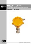
CDL LINEAR HEAT SENSOR CABLE
Installation & User Manual
© 2011 DURAN ELECTRONICA S.L. - All rights reserved · www.duranelectronica.com
Certificate nr FS82426
I-manCDL-v03
TABLE OF CONTENTS
pages
1.INTRODUCTION. . . . . . . . . . . . . . . . . . . . . . . . . . . . . . . . . . . . . . . . . . . . . . . . . . . . . . . . . . . . . . . . . . . . . . . 5
2.FUNCTIONING. . . . . . . . . . . . . . . . . . . . . . . . . . . . . . . . . . . . . . . . . . . . . . . . . . . . . . . . . . . . . . . . . . . . . . . . 5
3.INSTALLATION. . . . . . . . . . . . . . . . . . . . . . . . . . . . . . . . . . . . . . . . . . . . . . . . . . . . . . . . . . . . . . . . . . . . . . . . 6
4.
WORKING TEST. . . . . . . . . . . . . . . . . . . . . . . . . . . . . . . . . . . . . . . . . . . . . . . . . . . . . . . . . . . . . . . . . . . . . . . 7
5.
TECHNICAL CHARACTERISTICS . . . . . . . . . . . . . . . . . . . . . . . . . . . . . . . . . . . . . . . . . . . . . . . . . . . . . . . . . . 8
6.CONNECTIONS. . . . . . . . . . . . . . . . . . . . . . . . . . . . . . . . . . . . . . . . . . . . . . . . . . . . . . . . . . . . . . . . . . . . . . . . 9
7.
DL DISTANCE LOCATOR UNIT. . . . . . . . . . . . . . . . . . . . . . . . . . . . . . . . . . . . . . . . . . . . . . . . . . . . . . . . . . . . 9
8.ACCESSORIES . . . . . . . . . . . . . . . . . . . . . . . . . . . . . . . . . . . . . . . . . . . . . . . . . . . . . . . . . . . . . . . . . . . . . . . . 14
9.GUARANTEE. . . . . . . . . . . . . . . . . . . . . . . . . . . . . . . . . . . . . . . . . . . . . . . . . . . . . . . . . . . . . . . . . . . . . . . . . . 15
I-manCDL-v03
3
4
© 2011 DURAN ELECTRONICA S.L.
All rights reserved · www.duranelectronica.com
1. INTRODUCTION
CDL sensor cable for fire detection is provided of two twisted steel conductors, covered by a heat-sensitive polymer. When the
programmed temperature is reached, this polymer layer gets broken, making the two conductors contact each other, causing
an alarm.
An outer extrusion, which is corrosion and abrasion resistant, protects the two conductors. This makes CDL linear heat sensor
cable to be the most adequate fire detection system for extreme environmental conditions.
1.1 Temperature ranges and outer extrusion types
There are 4 different types of CDL heat sensor cables, depending on the alarm temperature chosen: 68ºC, 78ºC, 88ºC and 105ºC.
Maximum room temperature*
Alarm temperature**
CDL68
45ºC/113ºF
68ºC/155ºF
CDL78
50ºC/122ºF
78ºC/173ºF
CDL88
70ºC/158ºF
88ºC/190ºF
CDL105
70ºC/158ºF
105ºC/220ºF
*Maximum temperatures recommended, considering potencial fluctuations in room temperature
**CDL cable alarm temperature does not depend on the length of the cable.
CDL cable is also available with different outer extrusions, depending on the applications given to the cable:
• Standard: For general applications, resistant to dust, humidity, dirt and common chemical agents, usually aggressive.
• Polypropylene: Thermal stability, durability, chemical resistant to abrasion and corrosive gases.
• Nylon: Extra protection for mechanical risk damage. Covered with nylon, ready to work under harsh industrial
environments.
2. FUNCTIONING
When reaching the pre-established temperature, the polymer layer surrounding the two conductors melts, making them to
contact each other, and thus producing an alarm.
After the alarm, the affected part of the cable must be replaced. There is no need to replace the whole cable, only the damaged
part, using a connections cable or any other useful device for this purpose.
I-manCDL-v03
5
Mechanical tension is kept constant through the whole length of the cable. If continuity is broken, it will lead to an open circuit
fault condition.
For the continuous monitoring of the cable, it is required to connect it to a conventional fire control panel or an analogical one
with a conventional zone module, with no need to use additional software. Take into account that the loop or module line must
be compatible with cable resistance levels (164 ohms/km) and capable of giving an alarm short-circuit signal.
The distance locator DL -connected to a fire panel- is capable of detecting the “exact point of alarm” along the cable length,
with a maximum distance of 3.000 m.
3. INSTALLATION
CDL thermal cable can be connected to a fire detection conventional panel or an analogical fire panel through a conventional
zone module. For its installation with a DL distance locator go to chapter 7 “DL Distance Locator.”
CAUTION: Do not connect CDL linear heat cable to the power supply.
1. At installation, the cable must always start with the junction box and finalize with an end of line box, provided with
an end of line resistor, whose values must be adequate to the control unit to which it will be connected.
2. In order to assure an easy and efficient installation, it is recommendable to keep the cable tight while its installation,
and uncoil only the cable pieces that will be installed.
3. It must be installed without any kind of deviation.
4. Installation should be done at an ambient temperature above -10ºC.
5. Install the cable at the ceiling level or in side walls, at 50cm. maximum from the ceiling.
6. Distance between a cable line and another one must not exceed 10,6m – coverage area -.
7. Connect a 1,5mm. copper wire – interconnection cable – from any DL Distance Locator or fire control unit to the
risk area, from which the CDL thermal cable will be connected afterwards.
8. Make sure that when installing CDL cable there are no elements at the installation that might make maintenaince
or repairing operations difficult.
9. The system does not require calibration.
6
© 2011 DURAN ELECTRONICA S.L.
All rights reserved · www.duranelectronica.com
3.1 Recommendations
Follow these recommendations for installing the CDL cable.
1. Check the cable befote its installation and make sure that it corresponds to the alarm temperature for which it
has been chosen.
2. Throw the cable following installation design.
3. Make sure that junctions have been made correctly, taking care that the maximum distances between the supports
follow the specifications from the manufacturer.
4. Make sure that the cable has not been installed on sharp edges and that no curve exceeds the minimum ratio of
7,2cm.
5. Verify that the value for the end of line resistance is correct, and adequate for the equipment to which the cable
will be installed.
6. Check that the end of line resistance is 164 ohms/Km per conductor maximum.
7. Disconnect any extinction and/or fire detection system which might be connected to the cable before going on
with the installation procedures (please remember to connect them again once the process has ended).
8. Check if the cable is correctly connected, in FAULT situation – open circuit- and FIRE – shortcircuit.
9. If you have installed a DL Distance Locator unit, please proceed as indicated in this manual in chapter 7.
3.2 Accessories
CDL sensor cable is provided with a wide range or accessories, in order to cover all installation needs.
It is advisable to use CDL accessories with CDL sensor cable, in order to guarantee the correct functionning of the product.
See the appendix with accessories listing in page 14.
4. WORKING TEST
Make sure that any element connected to the CDL cable – included those that might receive alarm cable condition – are
disconnected before proceeding with the following test.
We recommend choosing one of the two following options – the most adequate selection will depend on the user-.
4.1 Option 1
Fault state: disconnect one of the cable conectors from one of the line endings (beginning-end). After checking that the
messages are received correctly, connect the connector again and reset the system.
Alarm state: shortcircuit the conductors in any junction, in the control units connection or at the end of the line. After checking
that the messages are received correctly, free the shortcircuit and reset the system.
I-manCDL-v03
7
4.2 Option 2
Fault state: follow instructions from Option 1.
Alarm state:
1. Disconnect CDL cable from the DL Distance Locator unit or from the junction box.
2. Place a thermal cable of similar characteristics to the CDL thermal cable – or a piece of the CDL cable itself- and
place a end of line resistance in order to avoid open circuit fault.
3. Heat the testing piece of cable (with a warm air generator or similar) until the alarm is produced.
4. Connect CDL thermal cable again and reset the system.
This test must never be done in areas classified as hazardous.
5. TECHNICAL CHARACTERISTICS
8
Material
Silvered copper with galvanized steel, covered with a heat sensitive polymer
Outer extrusion diameter
0,912 mm
Conductor diameter
0,294 mm
Resistance
164 ohms/Km
Electrical range
30V AC -42,2V DC- 10A
Dielectric resistance
500V DC –UL tested –
Minimum exposure temperature
-40ºC – UL tested -
Minimum installation temperature
-10ºC
Accuracy at alarm temperature
+/-3% alarm temperature
Coverage area
10,7m – U.L. verified -
Tension – UTS-
1.700 N/mm2 minimum – EN 60811-1 BS tested
Minimum curve ratio
76.2 mm
Coil gross weight (1000m)
26,6 Kgs.
Coil diameter (1000m)
46 cm Ø
© 2011 DURAN ELECTRONICA S.L.
All rights reserved · www.duranelectronica.com
6. CONNECTIONS
6.1 Junction box
Cable gland. Water resistant for leader cable
IP65 Plastic cover
Tri-metallic conductors
CDL Cable in detection area
20 mm. Cable gland
CDL Cable in detection area
6.2 End of line box
End of Line resistor
IP65 Plastic cover
CDL thermal cable
20 mm. Cable gland
CDL Cable in detection area
7. DL DISTANCE LOCATOR UNIT
DL Distance locator, connected to CDL thermal cable, displays the exact point of alarm in a cable length of 3.000 meters; making
easier to find the point of alarm.
DL Distance locator can be used with the CDL thermal cable and it can be connected to:
• Conventional fire panel system.
• Addresable fire panel, using a conventional zone module (pic.2)
I-manCDL-v03
9
(pic.1)
(pic.2)
The DL Distance Locator unit works independently from the fire control panel, so if an eventual problem happens –voltage dropsthis wont affect the fire panel system.
DL Distance locator is certified by FM (3023073) and UL (S24018).
7.1 Installation without leader cable
In the first installation the LHD cable is connected directly to the DL Distance Locator unit via the LHD
IN terminals (see pic 3 below). The DL Distance Locator is then connected to the fire alarm control/releasing panel or addressable
module via the LHD OUT terminals. Power is supplied either from the auxiliary power output of the panel or module or from a
separate listed power supply.
(pic.3)
10
© 2011 DURAN ELECTRONICA S.L.
All rights reserved · www.duranelectronica.com
In this configuration the following steps should be followed during the first installation:
1. Apply power to the DL Distance Locator.
2. The display will show “Installation” for approximately 2 seconds.
3. The display will show “Cal Leader Cable” on the top line and “Yes” on the bottom line.
4. Press the SELECT button to change the bottom line to “No”.
5. Press the SET button.
6. The display will show “Calibrated” on the top line and “0 mV” on the bottom line.
7. Press the SET button again to continue.
8. The display will show “Select Cable” on the top line and “68 C/154 F” on the bottom line.
9. Press the SELECT button to change the cable to the appropriate type.
Alarm temperature
CDL68
68ºC/155ºF
CDL78
78ºC/172ºF
CDL88
88ºC/190ºF
CDL105
105ºC/220ºF
10. Once the correct cable is selected press the SET button.
11. The display will scroll “Alarm Point Distance Locator - ” across the top line and “Normal
Operation” on the bottom line
If the unit has been installed and power is being restored the following steps will occur:
• The display will read “Installed” on the top line for approximately 2 seconds.
• The display will read “Leader Cable Cal” on the top line and “0 mV” on the bottom line for
approximately 2 seconds.
• The display will read “Cable Selection” on the top line and the cable type which was
selected at installation on the bottom line for approximately 2 seconds.
• The display will scroll “Alarm Point Distance Locator - ” across the top line and “Normal
Operation” on the bottom line.
7.2 Installation with leader cable
In the second installation a leader cable is connected between the LHD cable and DL Distance Locator unit via the LHD IN
terminals (see Drawing 2 below). The DL Distance Locator is then connected to the fire alarm control/releasing panel or
addressable module via the LHD OUT terminals. Power is supplied either from the auxiliary power output of the panel or module
or from a separate listed power supply.
To install the Distance Locator DL :
1. Power the DL.
2. The display will show “Installation” for approximately 2 seconds.
3. The display will show “Cal Leader Cable” on the top line and “Yes” on the bottom line.
I-manCDL-v03
11
4. For the calibration procedure make sure the two ends of leader cable are connected together at the junction box.
5. Hold down the distance locate switch and press the SET button.
6. The display will show “Calibrated” on the top line and a value dependant on the length of leader cable in “mV” on
the bottom line. (Once the value is display the distance locate switch can be released).
7. Press the SET button again to continue.
8. The display will show “Select Cable” on the top line and “68ºC/154ºF” on the bottom line.
9. Press the SELECT button to change the cable to the appropriate type.
Alarm temperature
CDL68
68ºC/155ºF
CDL78
78ºC/172ºF
CDL88
88ºC/190ºF
CDL105
105ºC/220ºF
10. Once the correct cable is selected press the SET button.
11. The display will scroll “Alarm Point Distance Locator - ” across the top line and “Normal
Operation” on the bottom line
If the unit has been installed and power is being restored the following steps will occur:
• The display will read “Installed” on the top line for approximately 2 seconds.
• The display will read “Leader Cable Cal” on the top line and the previously stored calibration value in “mV” on
the bottom line for approximately 2 seconds.
• The display will read “Cable Selection” on the top line and the cable type which was selected at installation on
the bottom line for approximately 2 seconds.
• The display will scroll “Alarm Point Distance Locator - ” across the top line and “Normal Operation” on the
bottom line.
12
© 2011 DURAN ELECTRONICA S.L.
All rights reserved · www.duranelectronica.com
7.3 Locating the exact point of alarm
Once the DL Distance Locator unit has been correctly installed, during normal operation the display will scroll Alarm Point
Distance Locator - across the top line and Normal Operation on the bottom line.
In the event of an alarm being initiated on the fire alarm control/releasing panel due to a short on the linear heat detection
cable the Distance Locate Switch should be held down. A slightly delay (less than 1 second) will occur while the unit calculates
the distance to the alarm point before the display will read Alarm Point on the top line.
The bottom line will then display the distance along the cable to the alarm point from the beginning of the linear heat detection
cable.
While the Distance Locate switch is held down the unit will cycle between displaying the alarm point distance in metres and
feet.
During the time the Distance Locate switch is held down the linear heat detection cable will be electrically disconnected from
the fire alarm control/releasing panel or addressable module and subsequently put the panel or module into a trouble condition.
This is deliberate and intended and will ensure that the DL Distance Locator cannot be left in the Distance Locate position
accidentally.
Once the Distance Locate switch is released the linear heat detection cable will be electrically reconnected to the fire alarm
control/releasing panel or addressable module.
It should be noted that during normal operation the linear heat detection cable is completely electrically disconnected from the
DL Distance Locator unit and therefore tolerant of any faults which may occur in the unit.
7.4 Reseting installing parameters
If the incorrect cable type was selected or leader cable calibration was performed incorrectly it is possible to reset the DL
Distance Locator unit to the initial state so the installation parameters may be reprogrammed.
To perform a reset hold down the SET and SELECT buttons while the unit is off and power the unit up holding down the buttons.
The display will read installed and then change to installation after approximately 2 seconds of holding the buttons down. The
installation procedure should then be repeated according to the type of installation.
7.5 Technical characteristics
Operating voltage
9 – 28 V DC
Current consumption
Less than 10 mA. Normal operating Less than 90mA. Alarm point locating
Operating temperature Range
0 – 49ºC
Accuracy
15 - 25ºC < ±5% of alarm point distance
0 -15ºC and 25 – 49ºC < ±6.5% of alarm point distance
Protection range
IP65 / IK08
Size (mm)
180 x 130 x 78
Display
2 line, 16 character backlit display showing alarm point switching between
metres and feet, installation options and scrolling message when in normal
operation
Measurement
Meters and feet
Enclosure (Cable entries)
Long side: 3 x PG13.5/PG9
Short side: 2 x PG21/PG18
I-manCDL-v03
13
8.- ACCESSORIES
The correct functioning of the CDL sensor cable will depend on its correct installation. The inadequate subjection of the cable or
a wrong cable lying will make protection in the risk area to be lower or even impide detection.
It is recommended to use subjection clips, manufactured or accepted by the manufacturer at 1m. intervals. This way, the user
will avoid that the cable gets sagged, minizing the risk for mechanical damage.
Non metallic accessories have been halogen-free manufactured.
Be especially careful with adherent accessories. Make sure that the surfaces where they will be placed are totally clean.
8.1 Fastening accessories
Cable clip
Black Nylon. indicated from -40º to 85ºC
4.8mm mounting hole
wallplug holder
Installation with Ø 6 drill bit
30 Kg resistance
Poliamide 6
Halogen free
14
© 2011 DURAN ELECTRONICA S.L.
All rights reserved · www.duranelectronica.com
9. GUARANTEE
DURAN ELECTRONICA guarantees that CDL thermal cable and the DL distance locator have been manufactured to high
quality control standards.
CDL thermal cable is guaranteed against any manufacturing defect for 1 year after its purchase. If any anomaly were
detected during this period of time, please tell your provider or installer.
Guarantee covers the complete reparation of the equipments which are considered to be defective by the
Technical Departament of DURAN ELECTRONICA. This guarantee will be valid only if the equipment has been installed
by a competent person, and following the specifications in this manual.
Its negligent use or installation will exempt DURAN ELECTRONICA from any responsibility for the damages that might have
been caused to objects and/or people, and the fulfilling of these guarantees terms.
Guarantee does not cover:
• Installations, periodic checkings and maintenance operations.
• Repairs caused by improper manipulation, inappropriate use, negligence, overload, inadequate power supply or equipment
abandonment, tension desviations, defective installations, and other external causes.
• Repairs or fixes made by personnel not authorised by DURAN ELECTRONICA.
• Equipment transportation costs.
DURAN ELECTRONICA holds the right to make improvements or introduce amendments to this equipment without prior
notice.
I-manCDL-v03
15
c/ Tomás Bretón, 50
28045 MADRID, Spain
Tel: +34 91 528 93 75
Fax +34 91 527 58 19
[email protected]
www.duranelectronica.com
Certificate nr FS82426
I-manCDL-v03