1
US008671241B2
(12)
United States Patent
(10) Patent N0.:
(45) Date of Patent:
Molloy
(54)
SYSTEMS AND METHODS FOR USING
(56)
U~S~ PATENT DOCUMENTS
SYSTEM REDUCED POWER STATE
6,967,869 B1
11/2005 Kolokowsky
7,904,635 B2 *
Inventor:
Mar. 11,2014
References Cited
RESERVED SOLID STATE NONVOLATILE
MEMORY STORAGE CAPACITY FOR
(75)
US 8,671,241 B2
3/2011
Deng et a1. .................. .. 711/103
Michael K. Molloy, Round Rock, TX
2009/0327608 A1
(Us)
2011/0078364 A1
3/2011 Lee et al.
2011/0082987 A1
4/2011 Sauber et al.
2011/0099320 A1
4/2011
_
(73) Ass1gnee: geélfroducts LP, Round Rock, TX
12/2009 Eschmann et al.
Lucas et al.
OTHER PUBLICATIONS
Super Talent, “SSD User Manual”, Printed from Internet Jul. 29,
(*)
Notice:
Subject to any disclaimer, the term of this
2011, 8 Pg$~
patent is extended or adjusted under 35
_
U.S.C. 154(1)) by 219 days.
_
* med by examlner
Primary Examiner * Mardochee Chery
(21)
APP1~ N05 13/231,504
(74) Attorney, Agent, or Firm * Egan, Peterman & Enders
LLP
(
22
)
F1 d:
S
1e
6P
(65)
. 13 2011
’
(57)
Prior Publication Data
ABSTRACT
Systems and methods that may be implemented to utilize the
same portion of solid state nonvolatile memory for both man
US 2013/0067137 A1
(51)
Int. Cl.
(52)
us CL
Man 14, 2013
G06F 12/00
(58)
aging system running data during a system Working state and
to store previous Working state data Written from system
volatile memory during a loW poWer state When the system
volatile memory is depoWered. The previous Working state
information may include data and instructions that may be
(2006.01)
USPC ................................. .. 711/103; 711/E12.008
employed to restore the Previous Working State Of the infor
Fi61 d of Classi?cation Search
mation handling system prior to entering the loW poWer state
USPC
711/103 E12 008
and terminating poWer to the system volatile memory.
See application ?le for complete search history.
24 Claims, 8 Drawing Sheets
f 4.00
Command Arrives '
......................... ..
492
; 4'15
I
Follow Mapr ing
Read Flash lock "—* Return
>
_
_
Era-Sea Pia-Sh '
r 422
Yes
Blank m Avarrabie
‘7
--
1
"
f 424
Wrile Data To
Ma Newi Written
Previeusiv Erased we
’ Spam?
Fiash Biock
Flash 8 oak To
Logrcal Block
i
Yes
1
-
f 408
,. Na
Wrrte To Unma ped
' 428
Erased ISiock- opy
"
Rama! Fiii Ii
Necessary
Map Newiy
4, Wriiien
' Unerasad Fiash
_ Black In nvariable
r 4'10
.
spac
Flash Black To Lqgrcal
436
Bioek (Unwrap ing
Fiash 5 ask Wit Old
Data)
i
f 412
Scheriuie Previously
Mapped
Fiash Bier; —»@
For Erasing (6C)
- 414
f 430
, 432
‘
es
Erase Hash
$108k
___ Write Data And Map
To Logical Block
Return
426
US. Patent
Mar. 11,2014
Sheet 1 of8
US 8,671,241 B2
_
ME?wglam_
m
m
§\
$1
E551
"ME ZQEQ “uQ5%?kiEmMw,E?.
£1ET,n_W519i?
rEi_
fa:
n
n
“2,,
"
Q2
_gm/
u
,1. _5%
mgm
,9
"1.;n
m?w
mm,n,\$M3Q165,E23
,,n
,m"
é,1m?y
/M_mw? guzaom “"am o;
Mat,
nQ E
n
_
“M
1052Q5
_J.
M““£381
MWm?mm?_wmgmw
US. Patent
Mar. 11,2014
Sheet 2 of8
US 8,671,241 B2
US. Patent
Mar. 11,2014
Sheet 3 018
US 8,671,241 B2
A/SOO
Sysinitéaiiza‘iion
~ “ .......... NV
Said
Memory
Stat
“
I. ~ ~ ...................................................................
.............................. .. ..
Yes
Setup For Fast
Su$pend~Pmnt
Hibernation E/@ To
Reserve Area
/ 3m
US. Patent
Mar. 11,2014
Sheet 4 of8
US 8,671,241 B2
US. Patent
Mar. 11,2014
Sheet 5 018
US 8,671,241 B2
' 692
1‘ Restore Requested
V
V
Scheduie AiE
Deiayed
3"
V
Read Eiuck From f 6'94
Reserve Space To
Na
'
"
......... , :
3
‘
StartErase {3?
i/Q Queues
Na
Empty
£595
Siockén Reserve
Space
0
.
‘
.. . ,
is Garbage
~
Yes
Seiect Reserve
Biock to Writs;
Memory image
~»
" And
- Re?ne
PCEe S ace
Cs?eciien
‘ Yes
U
EsMemQ
/ 510
610
_' Continue Resume Q
+Write image
To Seiecteci Biock
FIG. 6
US. Patent
Mar. 11,2014
Sheet 7 018
US 8,671,241 B2
i/ 800
Hibernaie Qperariarr
If
i
.
Quiescent
<)
Stsrage
/
Physicai Fiagh ieczks
Lagisai Data mcks
Dara Brock i
Dara Break 2
Sara Bio-ck 3
Unerased Dara Brock?
Dara Bicrck 5
Erased Brock?
Dara Brock 6
Data Bicck 7
Erased Break 2
Unerased Dara Brock 2 ~'
Fiash
Fresh
Hash
Hash
Bisck 1
Bicrck 2
Black 3
Biock 4
'I '
Erased Break 3
DRAM Data Brack M
DRAM Daria BEQCk MM ;
Frash Bicrck NH
Fiash Brock N
Harsh Biock NH
DRAM Dara Brock rvr+r<
Flam Biask 2N
F! (1, 8
US. Patent
Mar. 11,2014
Sheet 8 018
US 8,671,241 B2
A/ 9G0
Raatare Oparatian
/ Lagiaai ata Easks
;
Data Steak?
:
Bata Biack 2
1
am am a
'
Active
/
Phyaiaai Hash iaaka
,
Fiaah Biack’i
‘
,
‘
'
Fiaah Biack 2
' "
'1
Unaa'asaa Eaia Biack 1 ‘
Hash
506K 4
Data BiQCk 5
Séaraga
Erased Biack?
/
Data Biack 6
962
Daia Biack 7
Erased Biack 2
,1 ;
‘\ Unerasad
ErasedDaia
BiockBiock
3 2 ‘
Fiash Biack N+’i
Erased Data Block M "
Fiash Block N
Erased Data Biock [VH1
Reserve
Rash Biack a
Hash Block NH
/
Sicrage
§\
Erased
904
'
Erasaa Data 5500a WK '
FIG, 19
a
Fiash Biack 2N
US 8,671,241 B2
1
2
SYSTEMS AND METHODS FOR USING
RESERVED SOLID STATE NONVOLATILE
MEMORY STORAGE CAPACITY FOR
SYSTEM REDUCED POWER STATE
ponents during the hibernation state (ACPI S4 state). Saving
information to a storage disk during the loW poWer S4 hiber
nation state requires less poWer than storing this information
in poWered DRAM during the loW poWer S3 suspend state.
HoWever, saving information to non-volatile storage disk dur
ing S4 hibernation state requires additional time for entering
and recovering from the hibernation state, making these
operations sloWer. Using such a hibernation technique also
TECHNICAL FIELD
This disclosure relates generally to information handling
systems, and more particularly to storage of information dur
ing reduced system poWer state.
requires a disk drive to spin up and then be read to restore the
last Working state data to DRAM When restoring a system
from a very loW poWer state. This process can be very sloW, as
BACKGROUND
copying and restarting can take a relatively long time, espe
cially for large DRAM systems like servers. To help speed
As the value and use of information continues to increase,
individuals and businesses seek additional Ways to process
and store information. One option available to users is infor
recovery from S4 hibernation state, all Working state DRAM
contents (OS, applications and data) may be stored in fast
non-volatile storage. Saving recovery data to ?ash memory of
a solid state drive (SSD) during hibernation may be employed
mation handling systems. An information handling system
generally processes, compiles, stores, and/or communicates
to further speed recovery from the suspend state, but requires
information or data for business, personal, or other purposes
thereby alloWing users to take advantage of the value of the
a lot of additional storage space on the SSD to be allocated for
20
information. Because technology and information handling
An SSD controller cannot Write over an unerased ?ash
needs and requirements vary betWeen different users or appli
memory block. Erasing cells on solid state ?ash memory to
prepare put a ?ash memory block in a state that alloWs Writing
cations, information handling systems may also vary regard
ing What information is handled, hoW the information is
handled, hoW much information is processed, stored, or com
this purpose, Which increases storage expense for the system.
25
municated, and hoW quickly and e?iciently the information
is several orders of magnitude sloWer than the act of Writing to
the ?ash memory block. Therefore, SSD controllers typically
reserve about 20% to 50% of the total capacity of an enter
may be processed, stored, or communicated. The variations in
prise SSD for “data garbage collection” (i.e., for accumula
information handling systems alloW for information handling
reservations, enterprise data storage, or global communica
tions. In addition, information handling systems may include
tion of data that is no longer to be saved). At any given time,
this reserved data garbage collection space is either already
erased (i.e., making Writing of neW data fast) or is in the
process of being erased. It does not contain any saved data. In
this Way, the reserved data garbage collection space elimi
a variety of hardWare and softWare components that may be
con?gured to process, store, and communicate information
nates the need for a Write operation to go through an erase
cycle before its data can be Written to the SSD.
systems to be general or con?gured for a speci?c user or
speci?c use such as ?nancial transaction processing, airline
and may include one or more computer systems, data storage
30
35
systems, and netWorking systems.
SUMMARY OF THE INVENTION
Information handling systems (such as computer Worksta
tions, desktop computers and portable computers), often
Disclosed herein are systems and methods that may be
employ loW poWer states and storage techniques that limit the
amount of poWer consumed by the systems during periods of
implemented to optimiZe solid state nonvolatile memory allo
cation betWeen different operating modes of an information
handling system. The disclosed systems and methods may be
40
inactivity While maintaining the operating state (e.g., loaded
applications and data) of the system. One example of such a
implemented to utiliZe the same portion of solid state non
technique is a reduced poWer state knoWn as “suspen ” (alter
volatile memory for both managing system running data dur
ing a system Working state and to store previous Working state
natively “sleep” or “standby”). During one type of conven
tional suspend state (i.e., Advanced Con?guration and PoWer
Interface “ACPI” S3 poWer state), information (e.g., data and
instructions) required to maintain the last Working operating
state of the information handling system is maintained in
poWered dynamic random access volatile memory (DRAM).
While in such a suspend state, poWer to other unneeded cir
cuitry of the system is cut off until the machine is Woken up
again for use, at Which time poWer is restored to the other
components of the system and the saved operating state infor
mation maintained in the poWered memory used to restore the
information handling system to its last Working operating
state. Using this conventional suspend technique, poWer is
45
during a hibernation state such as ACPI S4 state or other type
of loW poWer state. In particular, the disclosed systems and
methods may be implemented to optimiZe storage of previous
50
state non-volatile memory Which includes storing of previous
55
a loW poWer state (e.g., such as hibernation state) of an infor
mation handling system, such as a server. This previous Work
ing state information may include data and instructions that
may be employed to restore the previous Working state of the
information handling system prior to entering the loW poWer
(e. g., hibernation) state and terminating poWer to poWered
information handling systems, such as servers, do not cur
60
Another type of conventional loW poWer technique com
monly refers to “hibernation” copies all information (e.g.,
data and instructions) required to maintain the last operating
state of the information handling system from poWered
DRAM memory to a non-volatile storage disk so that poWer
Working state data on Flash memory or other type of solid
Working state information (e.g., data and instructions) during
consumed by the poWered memory at all times While the
system is in the suspend state. Additionally, some types of
rently support S3 (suspend to RAM) state.
data Written from system volatile memory during a loW poWer
state When the system volatile memory is depoWered, e.g.,
system volatile memory such as DRAM.
In one exemplary embodiment, a non-volatile memory
controller may be con?gured to use the existing reserve space
on a solid state non-volatile memory device to save previous
Working state information needed for recovery from a loW
poWer state operation (e.g., a S4 hibernation state operation)
65
for an information handling system Without competing for
to the poWered memory of the information handling system
normal non-reserved memory space on the non-volatile
may be cut off together With poWer to the other system com
memory device of the type that is used for data storage during
US 8,671,241 B2
3
4
a higher power Working state of the information handling
poWered volatile memory (e.g., DRAM) When the informa
tion handling system is entering the loW poWer (e.g., S4
system. In this Way, the reserved (data garbage collection)
space of a non-volatile memory space may be e?iciently used
hibernation) state. The Working state information may be
such that during a loWer poWer (e.g., hibernation) state of the
information handling the reserved memory space holds a
copy of Working state information read from poWered volatile
memory, and during a higher poWer system Working state is
erased or in the process of being pre-erased for improved
Written to Write-to blocks of the reserved nonvolatile memory
space that Will not be managed and that are ?agged for future
erasing When a reserved space read command (e. g., such as a
“read from reserve space” command) is executed during res
toration of the system from the loW poWer (e. g., S4 hibema
tion) state to higher poWer (e. g., S0 Working) state.
By employing normally-reserved space of a solid state
performance (e.g., for “data garbage collection” purposes).
Thus, in this embodiment there is no requirement to allocate
or use non-reserved normal (non-data garbage collection)
storage space on the non-volatile device during the loW poWer
non-volatile memory device such as SSD, the disclosed sys
(e.g., hibernation) state.
utiliZe solid state non-volatile memory space that is not allo
In one exemplary embodiment, a ?ash controller algorithm
executed by a nonvolatile memory controller (e.g., ?ash con
troller) may be created, modi?ed and/or extended so that it
cated for saving data during higher poWer (e.g., S0 Working)
system state. Instead, such non-allocated (e.g., “data garbage
tems and methods may be advantageously implemented to
uses a reserved space of a non-volatile memory that is nor
collection”) space may be temporarily used during a loW
poWer system state in Which volatile memory is depoWered
mally used for accumulation of data that is no longer to be
(e.g., such as S4 hibernation state) for storing system Working
saved during normal Working system (e.g., ACPI S0) state,
and that is consequently typically only visible to a data gar
bage collection or other similar function of the nonvolatile
controller. Such a controller algorithm may be implemented
state information read from volatile memory in order to
20
Working state) Where the system volatile memory is repoW
ered. By then returning this non-allocated reserved nonvola
during a S4 hibernation operation to store a copy of the
system Working state information corresponding to the infor
mation maintained in the poWered system volatile memory
enable quick read-back of the data to the volatile date from the
nonvolatile memory and thus quick recovery from the loW
poWer system state to a high poWer system state (e.g., S0
25
(e. g., DRAM) during the previous system Working state. This
system Working state information may include, for example,
tile memory space to its normal use (e.g., for “data garbage
collection”) upon system restoration to the higher poWered
state, little or no additional expensive solid state device
memory space is required as compared to a conventional
copies of the OS, applications, other data and instructions that
Were present in poWered volatile memory prior to depoWering
system con?guration.
30
Advantageously, the disclosed systems and methods may
be implemented in one exemplary embodiment using PCle
3.0 speeds With ><4, such that 4 GBps may be the normal
bandWidth of the interface. Further, With parallel ?ash orga
niZation, high bandWidth may be made available, e.g., in one
the reserved data garbage collection space is already erased,
data Writes from poWered volatile memory (e. g., DRAM) for
the loW poWer state may be performed relatively quickly. In
this regard, at the moment of entering hibernation state, the
system Working state information from the poWered volatile
35
example to suspend a 64 GB server in less than 1 minute. The
disclosed systems and methods may also be employed in a
memory may be copied to the reserved nonvolatile memory
40
this memory.
During a loW poWer state such as S4 hibernation state, all
input/output (I/O) activity Will cease and there is no compet
ing use for the reserved (e.g., data garbage collection) space
of the non-volatile memory. Since most or substantially all of
variety of loW poWer states, including for storing “ready”
state information, e.g., for a large number of smaller servers
that are in a “ready” state for execution (e.g., provisioned and
(e.g., SSD) space, and then the volatile memory depoWered.
In one respect, disclosed herein is a method of storing
information on solid state nonvolatile memory that includes
Nonvolatile memory uses relatively loW poWer When not
accessed during the loW poWer state, and the disclosed sys
tems and methods may be con?gured so that a nonvolatile
controller (together With other system components such as
45
processor, volatile memory, etc.) also enters into a loW poWer
state during the loW poWer state. Upon restoration of the
system from the loW poWer (e.g., S4 hibernation) state to a
information in the volatile memory While the information
50
55
information handling system With no poWer provided to the
volatile memory; and Writing the system Working state infor
mation from the poWered volatile memory to the reserved
lel to the poWer up operations of the rest of the information
handling system.
60
information to the reserved nonvolatile memory space from
second space of the solid state nonvolatile memory for stor
age prior to depoWering the volatile memory during the sec
ond loWer poWer state of the information handling system in
be employed When entering loW poWer (e.g., S4 hibernation)
state to cause disabling of any restriction that during higher
poWer (e. g., S0 Working) state prevents Writing to the reserved
(e.g., data garbage collection) space of the nonvolatile
memory. This alloWs Writing of the system Working state
memory for data garbage collection during the ?rst Working
state of the information handling system; depoWering the
volatile memory during a second loWer poWer state of the
ing erasing the reserved nonvolatile memory space) in paral
In one exemplary embodiment, a reserved space Write
command (e.g., such as a “Write to res space” command) may
handling system is in the ?rst Working state With poWer pro
vided to the volatile memory; allocating a ?rst portion of the
solid state nonvolatile memory for storage of saved data and
reserving a second space of the solid state nonvolatile
copied into the repoWered volatile memory. After system
Working state information in the reserved nonvolatile
memory space has been read back to volatile memory, the
nonvolatile controller may then start its erase cycles (includ
providing an information handling system that itself includes
solid state nonvolatile memory, and volatile memory con?g
ured to only store date When poWer is provided to the volatile
memory. The method may further include: providing poWer
to the volatile memory during the ?rst Working state of the
information handling system; storing system Working state
higher poWer state (e.g., S0 Working state), the loWer poWer
state system components (e. g., such as volatile memory, pro
cessor, nonvolatile controller, etc.) enter a higher poWer state,
and the reserved nonvolatile memory space is read back and
booted) but in extremely loW poWer state.
Which no poWer is provided to the volatile memory.
In another respect, disclosed herein is an information han
65
dling system, including: solid state nonvolatile memory;
volatile memory; and one or more processing devices. The
one or more processing device may be con?gured to cause
US 8,671,241 B2
5
6
implementation of the following actions: provide poWer to
cessors or other types of suitable processing devices con?g
the volatile memory during a ?rst Working state of the infor
ured to interpret and/ or execute program instructions and/or
mation handling system, store system Working state informa
tion in the volatile memory While the information handling
system is in the ?rst Working state With poWer provided to the
process data. In some embodiments, processing device 155
may interpret and/or execute program instructions and/or
process data stored in system volatile memory 165, storage
media 185 and/or another component of information han
volatile memory, allocate a ?rst portion of the solid state
nonvolatile memory for storage of saved data and reserve a
second space of the solid state nonvolatile memory for data
dling system 150. System poWered volatile memory 165 (e. g.,
dynamic random access memory DRAM) may be coupled as
shoWn to processing device 155 via platform controller hub
garbage collection during the ?rst Working state of the infor
mation handling system, depoWer the volatile memory during
(PCH) 160 Which facilitates input/output functions for the
information handling system. System read only memory
(ROM) 161 (e.g., such as erasable programmable read only
memory “EPROM”, electrically erasable programmable read
a second loWer poWer state of the information handling sys
tem, and Write the system Working state information from the
poWered volatile memory to the reserved second space of the
solid state nonvolatile memory for storage prior to depoWer
ing the volatile memory during the second loWer poWer state
of the information handling system in Which no poWer is
provided to the volatile memory.
only memory “EEPROM”, etc.) is also provided as shoWn for
storing start up ?rmWare, such as system BIOS. Also shoWn
coupled to processing device 155 for this server embodiment
is netWork interface card (NIC) 157 that is provided to enable
communication across netWork 176 (e.g., such as the Internet
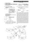
BRIEF DESCRIPTION OF THE DRAWINGS
20
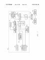
FIG. 1 illustrates a block diagram of an information han
dling system according to one exemplary embodiment of the
disclosed systems and methods.
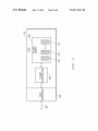
FIG. 2 illustrates a solid state nonvolatile memory accord
ing to one exemplary embodiment of the disclosed systems
and methods.
FIG. 3 illustrates methodology according to one exemplary
embodiment of the disclosed systems and methods.
FIG. 4 illustrates methodology according to one exemplary
embodiment of the disclosed systems and methods.
FIG. 5 illustrates methodology according to one exemplary
embodiment of the disclosed systems and methods.
FIG. 6 illustrates methodology according to one exemplary
embodiment of the disclosed systems and methods.
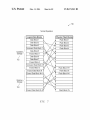
FIG. 7 illustrates a mapping relationship according to one
exemplary embodiment of the disclosed systems and meth
ods.
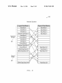
FIG. 8 illustrates a mapping relationship according to one
exemplary embodiment of the disclosed systems and meth
ods.
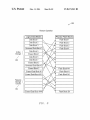
FIG. 9 illustrates a mapping relationship according to one
exemplary embodiment of the disclosed systems and meth
ods.
DESCRIPTION OF ILLUSTRATIVE
EMBODIMENTS
25
30
160 and its controller chip to enable the user to interact With
the information handling system 150 and programs or other
softWare/ ?rmware executing thereon. As further shown, the
exemplary information handling system 150 of this embodi
ment may also include a service processor 182 (e.g., such as
35
baseboard management controller “BMC”) running system
BIOS may also be coupled to PCH 160 and its controller chip
as shoWn. Service processor 182 may be, for example, run
40
ning real time OS or embedded Linux and also performing
tasks independent of the host and BIOS, such as cooling fan
control, etc. It Will be understood that the particular combi
nation of information handling system components of FIG. 1
is exemplary only, and that the disclosed systems and meth
45
FIG. 1 is a block diagram of an information handling
other type of information handling system (e.g., desktop com
puter, laptop computer, etc.) during a S4 hibernation or other
media drives 185 (e.g., hard disk drives, NVRAM, Flash or
other suitable media drive devices) or any other suitable form
of internal or external storage that may be coupled to PCH
160 and its controller chip to provide permanent storage for
the information handling system. One or more input devices
(e.g., keyboard 195, mouse/touchpad 197, etc.) and a display
device 175 (e.g., LCD display) together With its correspond
ing display controller 170 may be optionally coupled to PCH
system 150 as it may be con?gured as a computer server
system according to one exemplary embodiment of the dis
closed systems. In this regard, it Will be understood that the
server con?guration of FIG. 1 is exemplary only, and that the
disclosed systems and methods may be implemented on any
or local corporate intranet) With various multiple information
handling systems con?gured as netWork devices 1781-178”.
Still referring to FIG. 1, storage 185 may include storage
50
ods may be implemented With an information handling sys
tem that includes any other suitable combination of addi
tional, feWer or alternative information handling system
components (e. g., including one or more processing devices).
As further shoWn in FIG. 1, PCH 160 may be communica
tively coupled to solid state nonvolatile memory 187, for
example, via high speed bus such as a PCIe interface. Further,
optional additional solid state nonvolatile memory 188 may
be directly coupled as shoWn to processing device 155, e.g.,
via PCIe interface. Solid state nonvolatile memory 187 and/or
188 may include, for example, fast nonvolatile memory such
as ?ash memory, PCIe ?ash memory (including nonvolatile
type of loWer poWer state With depoWered memory to save
memory E “NVME”), NVDIMMs (nonvolatile dual in-line
memory modules), a PCIe (Peripheral Component Intercon
previous Working state information read from poWered sys
nect Express) add-in-card, a direct connect nonvolatile inter
tem volatile memory to system non-volatile memory so that
face (e.g., an ONFI (Open NAND Flash Interface Working
Group) interface), a SSD (solid-state drive), or another solid
state storage type con?gured for fast restart.
In the embodiment of FIG. 1, PCH 160 may be coupled to
55
the volatile memory may be depoWered and the Working state
information retained for later read-back to the volatile
memory When the system is recovered to a higher poWered
state and the volatile memory repoWered.
As shoWn in FIG. 1, information handling system 150 of
this exemplary embodiment includes at least one processing
device 155, Which may each be a central processing unit CPU
(e. g., such as an Intel Pentium series processor, an Advanced
Micro Devices (AMD) processor) or one of many other pro
60
other components With optional interfaces such as a PCIe
interface and device interfaces such as a USB (Universal
Serial Bus) interface, for example. It Will be understood that
65
non-volatile memory 187 and/or 188 may be con?gured as an
integral component Within a chassis of information handling
system 150 (e. g., internal SDD, board mounted NVRAM,
US 8,671,241 B2
7
8
etc.), or may be alternatively con?gured as an attached exter
enabled for fast hibernation to nonvolatile memory 187 by
nal memory device. Moreover, although separate storage
pointing the hibernation input/output (I/O) operations of the
operating system (e.g., Linux, WindoWs, etc.) to the reserved
media 185, non-volatile memory 187 and nonvolatile
memory 188 are shoWn provided in the embodiment of FIG.
(e.g., data garbage collection) space of solid state nonvolatile
memory 187, it being understood that another mechanism
besides the operating system (e.g., such as system BIOS) may
1, it Will be understood that a common non-volatile memory
device/ s may be alternatively employed to perform functions
of both storage media 185 and non-volatile memory 187, 188
that are described herein.
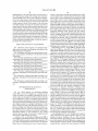
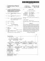
be employed to create and use memory area in the reserved
space of solid state nonvolatile memory 187 to store Working
FIG. 2 illustrates one exemplary embodiment of solid state
nonvolatile memory 187 that is con?gured as a solid state
state information. System setup continues in step 312.
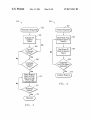
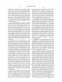
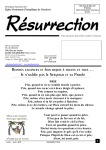
FIG. 4 illustrates one exemplary embodiment of operating
drive (SDD) to store information during operation of infor
management methodology 400 of a solid state nonvolatile
memory (e. g., such as solid state nonvolatile memory 187 of
mation handling system 150. It Will be understood that one or
more features and tasks of nonvolatile memory 187 may be
information handling system 150) that may be executed (e. g.,
alternatively implemented using nonvolatile memory 188
When present. In the embodiment of FIG. 2, SSD 187 includes
an array 208 of nonvolatile memory (Flash) memory ele
5
by nonvolatile memory controller 206 of FIG. 2) during a
system operation state in Which system volatile memory (e. g.,
volatile memory 165) is poWered. An example of such a
ments 210 to Which saved data is Written to and read back
system operation state is ACPI Working state S0, during
across data bus 202 (e.g., high speed PCIe 3.0 bus or other
suitable data bus such as serial advanced technology attach
ment “SATA”, serial attached SCSI “SAS”, etc.) via bus
interface 204. As shoWn, a nonvolatile memory (Flash) con
troller 206 (e.g., any suitable processing device such as
Which the memory controller 206 allocates a ?rst portion of
memory space of nonvolatile memory 187 for saved data, and
utiliZes a second memory space as reserved (e.g., data gar
20
bage collection) space that contains erased memory space and
memory space that holds non-saved data that is in the process
microprocessor, microcontroller, ASIC, FPGA, etc.) is pro
of being pre-erased. Although described in relation to opera
vided to control reads to and Writes from the ?ash memory
elements 210 of array 208. Nonvolatile memory controller
206 may be con?gured to reserve at least a portion of the
nonvolatile memory space (eg about 20% to 50% of the total
tion of solid state nonvolatile memory 187 (e.g., Flash
memory), it Will be understood that methodology 400 may be
capacity ?ash memory elements 210) as a “data garbage
collection” space for accumulation of data that is no longer to
be saved to nonvolatile memory 187 during higher poWer
25
alternatively implemented by any solid state nonvolatile
memory con?guration that is suitable for coupling to an infor
mation handling system for purposes of reading, Writing, and
erasing data therefrom.
30
system operation When volatile memory 165 is poWered (e.g.,
during ACPI system Working state S0). At any given time
during system Working state, this reserved data garbage space
is either already erased (i.e., making Writing of neW data fast)
or is in the process of being erased, and does not contain any
saved data. It Will be understood that this con?guration of
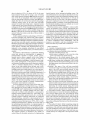
As shoWn, methodology 400 starts in step 402 Where a
command arrives across bus 202 at memory controller 206
from processor 155. If the command is determined to be a
35
read command for a given mapped memory block in step 404,
then the memory controller 206 folloWs the mapping of
memory array 208 to read the block in step 416, and then
returns to read another command in step 402. HoWever, if the
nonvolatile memory 187 is exemplary only, and that any other
command is not a read command (i.e., it is a Write command)
suitable con?guration of one or more nonvolatile memory
elements and/or one or more processing devices may be
then methodology 400 proceeds to step 406, Where it is deter
employed.
40
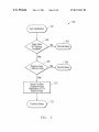
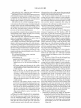
FIG. 3 illustrates fast hibernation setup methodology 300
that may be employed in one exemplary embodiment during
system initialiZation and boot up of information handling
system 150. The steps of methodology 300 may be performed
by, for example, processor 155 of information handling sys
45
tem 150 executing start up code stored on system ROM 161.
As shoWn in FIG. 3, system initialiZation begins in step 301
and proceeds to step 302 Where it is determined if solid state
nonvolatile memory 187 is available. If no solid state non
volatile memory is found available in step 302, then method
50
ology 300 proceeds With normal system con?guration and
operating system setup in step 304, e. g., including setting up
55
memory 187 is found present, then methodology 300 pro
ceeds to step 306 Where it is determined if the siZe of the
reserved (e.g., data garbage collection) space of solid state
nonvolatile memory 187 is at least as large as the siZe of
volatile memory 165. If the siZe of the reserved space of solid
responding logical block in step 424 before methodology 400
60
volatile memory 165, then methodology 300 proceeds With
normal system con?guration and operating system setup in
methodology 300 proceeds to step 310, Where the system is
If in step 406, the Write command data does not correspond
to a logically mapped data block of memory array 208, then it
is determined step 420 if an erased block is present in the
available (i.e., non-reserved) space of memory array 208. If
an erased block is found to be present in available space of
memory array 208, then the neW data is Written to this previ
ously erased block in step 422, and then mapped to the cor
state nonvolatile memory 187 is not as large as the siZe of
step 308, in a manner similar to step 304. HoWever, if the siZe
of the reserved space of solid state nonvolatile memory 187 is
at least as large as the siZe of volatile memory 165, then
memory array 208 (copying partial ?ll if necessary). In step
410, the neWly Written data block of the memory array is
mapped to the corresponding logical block, and the previ
ously mapped data block of memory array 208 (i.e., contain
ing old data corresponding to the same logical block) is
unmapped. The previously mapped data block is scheduled in
step 412 for erasing, and methodology 400 returns in step 414
to read another command in step 402.
system con?guration to save previous operating state infor
mation in poWered volatile memory 165 during a hibernation
or other loW poWer state. HoWever, if solid state nonvolatile
mined if the Write command data corresponds to a previously
mapped data block of memory array 208. If the Write com
mand data corresponds to a logically mapped data block of
memory array 208, then the neW data for the block is Written
in step 408 to a neW unmapped and erased data block of
65
returns in step 426 to read another command in step 402.
HoWever, if in step 420 it is determined step that an erased
block is not present in the available space of memory array
208, then it is determined in step 428 if an un-erased memory
block is present in the available space of memory array 208.
If such an un-erased memory block is found present in the
available space of memory array 208, then this block is erased
in step 430. The neW data is Written to this previously erased
US 8,671,241 B2
9
10
block in step 432 and mapped to the corresponding logical
When the information handling system enters the hibernation
block before methodology 400 returns in step 434 to read
another command in step 402. If in step 428 no un-erased
memory block is found present in the available space of
(e.g., S4) poWer state, and the system poWered volatile
memory is depoWered.
memory array 208, then methodology 400 terminates in step
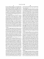
relationship 800 of logical memory blocks to physical solid
state nonvolatile memory blocks that may be implemented by
FIG. 8 illustrates one exemplary embodiment of a mapping
43 6 With an error. This error may be, for example, passed back
to the operating system for handling as a normal l/O error,
e.g., similar to a disk Write failure error. Depending on the
a nonvolatile memory controller (e.g., such as nonvolatile
memory controller 206) during a loW poWer state such as
data being Written, the step 436 may be executed to result in
hibernation (e.g., S4 poWer state) of an information handling
the error being passed back to an application to decide What to
do, or if the operating system Was doing a page out, it can
shoWn in FIG. 8, the same logical memory blocks previously
decide a course of action.
assigned to reserved (data garbage collection) storage space
system such as described above in relation to FIG. 5. As
FIG. 7 illustrates one exemplary embodiment of a mapping
704 during the higher poWer Working state of FIG. 7 are
relationship 700 of logical memory blocks to physical
together With their corresponding mapped physical memory
memory blocks that may be implemented by a nonvolatile
memory controller (e.g., such as nonvolatile memory control
blocks noW utiliZed (Without remapping) as storage space 804
by the nonvolatile memory controller for saving a copy of
Working state volatile memory information 804 (e.g., read
ler 206) during higher poWer normal operation of solid state
nonvolatile memory (e.g., during S0 poWer state), such as
from volatile DRAM memory 165) prior to depoWering the
described above in relation to FIG. 4. As shoWn in FIG. 7, a
volatile memory for the loW poWer state. As shoWn, the
remainder of the logical memory blocks of FIG. 8 remain
relatively large percentage (e.g., about 40%) of the logical
20
memory blocks are assigned to reserved (data garbage col
lection) storage space 704 and are mapped to physical
mapped to quiescent storage space 802 that contains data
saved during the Working state (e.g., S0) state of FIG. 7,
memory blocks of the nonvolatile storage that are maintained
although no reads or Writes of this information by the OS
occurs While the system is in the loWer poWer (e.g., S4) state
in pre-erased condition during a higher poWer (e.g., S0 Work
ing) system state. The remainder of the logical memory
25
blocks are assigned to active available storage space 702 that
is allocated for saved data and mapped to physical memory
blocks that contain saved data or that are ready to contain
saved data.
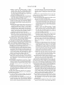
FIGS. 5 and 6 respectively illustrate hibernate and restore
methodologies 500 and 600 as these operations may be
30
implemented (e.g., by nonvolatile memory controller 206 of
of FIG. 8. Although not necessary, by optionally using the
same mapping of logical data blocks for both storage spaces
704 and 804, time savings may be realiZed for transition
betWeen higher and loWer poWer states. In this regard, it Will
be understood that the nonvolatile memory controller may
alternatively remap the logical blocks to at least some differ
ent physical blocks than Were previously allocated for the
reserve (data garbage collection) for Writing the Working state
solid state nonvolatile memory 187) With direct use of the
information from volatile memory, although this may take
reserve (data garbage collection) space of solid state nonvola
more time.
tile memory Without remapping and by using immediate
35
erase of the reserve space of the solid state nonvolatile
memory. It Will be understood, hoWever, that in an alternate
embodiment hibernate and restore operations may be con
ducted in any other suitable manner including, for example,
such that the management of the reserved solid state memory
space for the data garbage collection process may be per
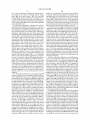
tile system memory When exiting a hibernation (e.g., S4)
poWer state or other poWer state during Which the system
volatile memory has been depoWered. As shoWn, methodol
40
resume to a Working state (e.g., S0 poWer state) for an infor
mation handling system. Methodology 600 proceeds to step
45
604 Where a given block is read from the reserved (data
garbage collection) memory space of the solid state nonvola
tile memory (e.g., nonvolatile memory 187 of information
handling system 150) and transferred to repoWered system
volatile memory (e.g., volatile memory 165 of information
ing on processor 155) at the initiation of a hibernation state
(S4 poWer state) for information handling system 150. Prior
ogy 600 starts in step 602 Where a restore read request is
received (e.g., from system BIOS executing on processor
155) upon exiting a hibernation state (e.g., S4 poWer state) to
formed asynchronously.
Hibernation storage methodology 500 of FIG. 5 may be
implemented to store Working state information prior to
entering a hibernation (e.g., S4) poWer state or other poWer
state in Which poWered volatile system memory is depoW
ered. As shoWn, methodology 500 starts in step 502 Where a
hibernation Write request is received (e.g., from BIOS execut
Restore methodology 600 of FIG. 6 may be implemented
to restore Working state information back to repoWered vola
50
handling system 150). After the given block is read in step
to proceeding, all delayed Writes for solid state nonvolatile
memory 187 are scheduled in step 504. Next, methodology
604, it is immediately erased from solid state volatile memory
in step 606 as shoWn. This process is repeated until all previ
500 does not proceed further until all input/output (l/O)
ously stored Working state information (together With any
queues of solid state nonvolatile memory 187 are found
empty in step 506, and all data garbage collection processes
(e. g., previously initiated erasing) are found completed With
respect to the reserved (data garbage collection) storage space
55
mation handling system then continues in step 610, With the
reserved (data garbage collection) space of solid state non
area of solid state nonvolatile memory 187 in step 508.
Next, in step 510 a given block of the reserved (data gar
bage collection) storage space is selected for Writing a corre
volatile memory being pre-erased and ready for Working state
60
sponding data image from system poWered volatile memory
(e.g., volatile memory 165), and the image is Written from
operation.
FIG. 9 illustrates one exemplary embodiment of a mapping
relationship 900 of logical memory blocks to physical solid
state nonvolatile memory blocks that may be implemented by
poWered memory to the selected block. This selection and
Writing process continues as shoWn until all data from the
system poWered volatile memory is saved in step 512 in the
reserved (data garbage collection) space of solid state non
volatile memory 187. Methodology 500 then terminates
data bus con?guration space, such as PCle space) is restored
in step 608 from solid state nonvolatile memory to repoWered
system volatile memory. The resume operation of the infor
a nonvolatile memory controller (e.g., such as nonvolatile
65
memory controller 206) upon system restoration from hiber
nation (e.g., S4 poWer state) to Working state (e. g., S0 poWer
state) of an information handling system such as described
US 8,671,241 B2
11
12
above in relation to FIG. 6. As shown in FIG. 9, the same
logical functions in the information handling system. The
logical memory blocks used for saving a copy of Working
state volatile memory information 804 during the loW poWer
executable instructions may comprise a plurality of code seg
ments operable to instruct the information handling system to
perform the methodology disclosed herein. It Will also be
state of FIG. 8 are immediately erased and reassigned as
reserved (data garbage collection) storage space 904 imme
diately after they are read from the reserved (data garbage
understood that one or more steps of the present methodolo
collection) memory space of the solid state nonvolatile
computer program. For example, a code segment executed by
memory for transfer and Writing back to repoWered system
volatile memory upon system restoration to the higher poWer
Working state of FIG. 9. The remainder of the logical memory
blocks that Were quiescent storage 802 during loW poWer state
the information handling system may include one or more
gies may be employed in one or more code segments of the
steps of the disclosed methodologies.
While the invention may be adaptable to various modi?
cations and alternative forms, speci?c embodiments have
been shoWn by Way of example and described herein. HoW
are noW assigned as shoWn to active available storage space
902 that is allocated for saved data and mapped to physical
ever, it should be understood that the invention is not intended
to be limited to the particular forms disclosed. Rather, the
invention is to cover all modi?cations, equivalents, and alter
natives falling Within the spirit and scope of the invention as
memory blocks that contain saved data or that are ready to
contain saved data.
It Will be understood that the methodologies of FIGS. 3, 4,
5 and 6 are exemplary only, and that each of these method
de?ned by the appended claims. Moreover, the different
ologies may be implemented using any combination of feWer,
additional and/or alternative steps that is suitable forperform
ing solid state nonvolatile memory operation management,
hibernation storage and Working state restoration operations,
20
respectively. Moreover, it Will be understood that one or more
of the memory controller tasks disclosed herein may be
What is claimed is:
1. A method of storing information on solid state nonvola
implanted in one exemplary embodiment by user-de?ned
commands using nonvolatile memory E PCle ?ash memory
standard.
For purposes of this disclosure, an information handling
system may include any instrumentality or aggregate of
25
solid state nonvolatile memory, and
30
manifest, detect, record, reproduce, handle, or utiliZe any
form of information, intelligence, or data for business, scien
ti?c, control, entertainment, or other purposes. For example,
memory While the information handling system is in the
?rst higher poWer state With poWer provided to the vola
a PDA, a consumer electronic device, a netWork storage 35
device, or any other suitable device and may vary in siZe,
shape, performance, functionality, and price. The information
handling system may include memory, one or more process
ing resources such as a central processing unit (CPU) or
40
the information handling system may include one or more
storage devices, one or more communications ports for com
45
one or more buses operable to transmit communications
betWeen the various hardWare components.
It Will be understood that one or more of the tasks, func
tions, or methodologies described herein (e.g., including
those performed by processor 155 and nonvolatile memory
controller 206) may be implemented by a computer program
depoWering the volatile memory during a second loWer
poWer state of the information handling system With no
poWer provided to the volatile memory; and
Writing a last system Working state information from the
poWered volatile memory to the reserved second space
of the solid state nonvolatile memory for storage prior to
loWer poWer state of the information handling system in
Which no poWer is provided to the volatile memory.
2. The method of claim 1, further comprising repoWering
Ware code or softWare code) embodied in a non-transitory
tangible computer readable medium (e.g., optical disk, mag
55
When executed (e.g., executed on a processing device of an
information handling system such as CPU, controller, micro
controller, processor, microprocessor, FPGA, ASIC, or other
suitable processing device) to perform one or more steps of
garbage collection during the ?rst higher poWer state of
the information handling system, the ?rst space of the
solid state nonvolatile memory being different than the
depoWering the volatile memory during the second
50
of instructions (e.g., computer readable code such as ?rm
netic disk, non-volatile memory device, etc.), in Which the
computer program comprising instructions are con?gured
tile memory;
allocating a ?rst space of the solid state nonvolatile
memory for storage of saved data and reserving a second
space of the solid state nonvolatile memory for data
second space of the solid state nonvolatile memory;
municating With external devices as Well as various input and
output (I/O) devices, such as a keyboard, a mouse, and a video
display. The information handling system may also include
volatile memory con?gured to only store data When
poWer is provided to the volatile memory;
providing poWer to the volatile memory during a ?rst
higher poWer state of the information handling system;
storing system Working state information in the volatile
an information handling system may be a personal computer,
hardWare or softWare control logic.Additional components of
tile memory, the method comprising:
providing an information handling system comprising:
instrumentalities operable to compute, classify, process,
transmit, receive, retrieve, originate, sWitch, store, display,
aspects of the disclosed systems and methods may be utiliZed
in various combinations and/or independently. Thus the
invention is not limited to only those combinations shoWn
herein, but rather may include other combinations.
60
the volatile memory to restore the information handling sys
tem to the ?rst higher poWer state; and reading the stored
system Working state information from the reserved second
space of the solid state nonvolatile memory and Writing the
read system Working state information back to the volatile
memory after repoWering the volatile memory to restore the
last system Working state information of the information han
dling system.
3. The method of claim 2, further comprising erasing the
stored system Working state information from the reserved
the methodologies disclosed herein. A computer program of
instructions may be stored in or on the non-transitory com
puter-readable medium residing on or accessible by an infor
second space of the solid state nonvolatile memory immedi
mation handling system for instructing the information han
ately after reading the stored system Working state informa
dling system to execute the computer program of instructions.
65
tion from the reserved second space of the solid state non
The computer program of instructions may include an
volatile memory for Writing back to the repoWered volatile
ordered listing of executable instructions for implementing
memory.
US 8,671,241 B2
13
14
4. The method of claim 1, Where the system Working state
information comprises data and instructions.
5. The method of claim 1, Where the ?rst higher poWer state
of the information handling system comprises an Advanced
Con?guration and PoWer Interface (ACPI) S0 poWer state;
information back to the volatile memory after repoWering the
volatile memory to restore the last system Working state infor
mation of the information handling system.
12. The system of claim 11, Where the one or more pro
cessing devices are further con?gured to cause implementa
tion of the folloWing actions: erase the stored system Working
state information from the reserved second space of the solid
and Where the second loWer poWer state of the information
handling system comprises ACPI S4 poWer state.
6. The method of claim 1, further comprising storing data
state nonvolatile memory immediately after reading the
stored system Working state information from the reserved
for future recovery in the ?rst space of the solid state non
volatile memory allocated for storage of saved data during the
?rst higher poWer state of the information handling system;
and storing no data for future recovery in the second space of
the solid state nonvolatile memory during the ?rst higher
poWer state of the information handling system.
7. The method of claim 6, further comprising erasing or
pre-erasing all data contained in the second space of the solid
state nonvolatile memory during the higher poWer Working
state of the information handling system.
8. The method of claim 1, Where the information handling
system is not con?gured to implement a loW poWer state in
Which the volatile memory remains poWered.
9. The method of claim 1, Where the step of Writing the
system Working state information from the poWered volatile
second space of the solid state nonvolatile memory for Writ
ing back to the repoWered volatile memory.
13. The system of claim 10, Where the system Working state
information comprises data and instructions.
14. The system of claim 10, Where the ?rst higher poWer
state of the information handling system comprises an
Advanced Con?guration and PoWer Interface (ACPI) S0
poWer state; and Where the second loWer poWer state of the
information handling system comprises ACPI S4 poWer state.
15. The system of claim 10, Where the one or more pro
20
higher poWer state of the information handling system; and
memory to the reserved second space of the solid state non
volatile memory further comprises directly using the reserved
cessing devices are further con?gured to cause implementa
tion of the folloWing actions: store the saved data for future
recovery in the ?rst space of the solid state nonvolatile
memory allocated for storage of saved data during the ?rst
25
second space of the solid state nonvolatile memory by Writing
the system Working state information from the poWered vola
store no data for future recovery in the second space of the
solid state nonvolatile memory during the ?rst higher poWer
state of the information handling system.
tile memory to the reserved second space of the solid state
16. The system of claim 15, Where the one or more pro
nonvolatile memory Without remapping logical blocks of the
cessing devices are further con?gured to cause implementa
reserved second space to physical memory blocks of the solid
30
tion of the folloWing actions: erase or pre-erase all data con
tained in the second space of the solid state nonvolatile
state nonvolatile memory.
10. An information handling system, comprising:
memory during the ?rst higher poWer state of the information
solid state nonvolatile memory;
volatile memory; and
one or more processing devices con?gured to cause imple
handling system.
35
mentation of the folloWing actions:
provide poWer to the volatile memory during a ?rst
higher poWer state of the information handling sys
18. The system of claim 10, Where the one or more pro
tem,
store system Working state information in the volatile
memory While the information handling system is in
the ?rst higher poWer state With poWer provided to the
volatile memory,
allocate a ?rst space of the solid state nonvolatile
memory for storage of saved data and reserve a sec
ond space of the solid state nonvolatile memory for
40
system Working state information from the poWered volatile
volatile memory by Writing the system Working state infor
45
state of the information handling system, the ?rst
space of the solid state nonvolatile memory being
depoWer the volatile memory during a second loWer
poWer state of the information handling system, and
Write a last system Working state information from the
poWered volatile memory to the reserved second
50
55
age prior to depoWering the volatile memory during
restore the information handling system to the ?rst higher
poWer state; and read the stored system Working state infor
mation from the poWered volatile memory to the reserved
second space of the solid state nonvolatile memory Without
remapping logical blocks of the reserved second space to
physical memory blocks of the solid state nonvolatile
memory.
space of the solid state nonvolatile memory for stor
the second loWer poWer state of the information han
dling system in Which no poWer is provided to the
volatile memory.
11. The system of claim 10, Where the one or more pro
cessing devices are further con?gured to cause implementa
tion of the folloWing actions: repoWer the volatile memory to
cessing devices are further con?gured to cause implementa
tion of the folloWing actions: directly use the reserved second
space of the solid state nonvolatile memory by Writing the
memory to the reserved second space of the solid state non
data garbage collection during the ?rst higher poWer
different than the second space of the solid state non
volatile memory,
17. The system of claim 10, Where the information han
dling system is not con?gured to implement a loW poWer state
in Which the volatile memory remains poWered.
19. The method of claim 1, further comprising using a Write
restriction to prevent Writing to the reserved second space of
the solid state nonvolatile memory during the ?rst higher
poWer state; and using a reserved space Write command When
entering the second loWer poWer state of the information
handling system to disable the Write restriction to alloW Writ
ing of the last system Working state information from the
poWered volatile memory to the reserved second space of the
solid state nonvolatile memory When the information han
dling system is entering the second loWer poWer state.
20. The method of claim 9, further comprising:
60
performing the folloWing steps during the ?rst higher
poWer state of the information handling system:
assigning a ?rst portion of logical memory blocks and
their corresponding mapped physical memory blocks
to the second space of the solid state nonvolatile
65
memory reserved for data garbage collection during
mation from the reserved second space of the solid state
the ?rst higher poWer state of the information han
nonvolatile memory and Write the read system Working state
dling system,
US 8,671,241 B2
15
16
assigning a second and different portion of logical
memory blocks and their corresponding mapped
ered volatile memory to the reserved second space of the
solid state nonvolatile memory When the information
physical memory blocks to the allocated ?rst space of
the solid state nonvolatile memory for storage of
saved data during the ?rst higher poWer state of the
handling system is entering the second loWer poWer
state.
23. The system of claim 18, Where the one or more pro
information handling system, and
cessing devices are further con?gured to cause implementa
tion of the folloWing actions:
saving data to the allocated ?rst space of the solid state
nonvolatile memory during the ?rst higher poWer
state of the information handling system;
perform the folloWing steps during the ?rst higher poWer
state of the information handling system:
assigning a ?rst portion of logical memory blocks and
then performing the folloWing steps When entering the
second loWer poWer state of the information handling
system from the ?rst higher poWer state of the informa
their corresponding mapped physical memory blocks
to the reserved second space of the solid state non
tion handling system and prior to depoWering the vola
volatile memory reserved for data garbage collection
during the ?rst higher poWer state of the information
tile memory:
utiliZing the ?rst logical memory blocks of the reserved
second space together With their same corresponding
mapped physical memory blocks to Write Without
remapping the last system Working state information
from the poWered volatile memory to the previously
reserved second space of the solid state nonvolatile
handling system,
assigning a second and different portion of logical
memory blocks and their corresponding mapped
20
memory When the information handling system is
entering the second loWer poWer state, and
assigning the saved data stored in the allocated ?rst
information handling system, and
saving data to the allocated ?rst space of the solid state
space of the solid state nonvolatile memory as quies
cent storage While the information handling system
25
remains in the second loWer poWer state; and
then depoWering the volatile memory during the second
loWer poWer state of the information handling system
state of the information handling system from the second
loWer poWer state of the information handling system:
repoWering the volatile memory to restore the information
handling system to the ?rst higher poWer state;
then reading the stored last system Working state informa
tion from given physical memory blocks of the reserved
dling system and prior to depoWering the volatile
30
35
second space of the solid state nonvolatile memory and
40
space of the solid state nonvolatile memory as quies
then immediately erasing each given physical memory
remains in the second loWer poWer state; and
block of the reserved second space of the solid state
45
cessing devices are further con?gured to cause implementa
tion of the folloWing actions When entering the ?rst higher
50
nonvolatile memory reserved for data garbage collec
tion; and
reassigning the allocated ?rst space of the solid state non
volatile memory from quiescent storage to active avail
able storage space that is allocated for storage of saved
data While the information handling system is in the ?rst
higher poWer state.
55
handling system to the ?rst higher poWer state;
then reading the stored last system Working state informa
tion from given physical memory blocks of the reserved
second space of the solid state nonvolatile memory and
to the volatile memory after repoWering the volatile
memory to restore the last system Working state infor
22. The system of claim 10, Where the one or more pro
60
mation of the information handling system; and
then immediately erasing each given physical memory
use a Write restriction to prevent Writing to the reserved
second space of the solid state nonvolatile memory dur
block of the reserved second space of the solid state
ing the ?rst higher poWer state; and
use a reserved space Write command When entering the
second loWer poWer state of the information handling
system to disable the Write restriction to alloW Writing of
the last system Working state information from the poW
poWer state of the information handling system from the
second loWer poWer state of the information handling system:
repoWering the volatile memory to restore the information
Writing the read system Working state information back
cessing devices are further con?gured to cause implementa
tion of the folloWing actions:
then depoWering the volatile memory during the second
loWer poWer state of the information handling system
With no poWer provided to the volatile memory.
24. The system of claim 23, Where the one or more pro
then immediately reassigning the ?rst portion of logical
memory blocks and their corresponding mapped physi
cal memory blocks to the second space of the solid state
memory When the information handling system is
entering the second loWer poWer state, and
assigning the saved data stored in the allocated ?rst
cent storage While the information handling system
mation of the information handling system; and
nonvolatile memory after the stored last system Working
state information is read from that given physical
memory block;
memory:
utiliZing the ?rst logical memory blocks of the reserved
second space together With their same corresponding
mapped physical memory blocks to Write Without
remapping the last system Working state information
from the poWered volatile memory to the previously
reserved second space of the solid state nonvolatile
Writing the read system Working state information back
to the volatile memory after repoWering the volatile
memory to restore the last system Working state infor
nonvolatile memory during the ?rst higher poWer
state of the information handling system; and
then perform the folloWing steps When entering the second
loWer poWer state of the information handling system
from the ?rst higher poWer state of the information han
With no poWer provided to the volatile memory.
21. The method of claim 20, further comprising perform
ing the folloWing steps When entering the ?rst higher poWer
physical memory blocks to the allocated ?rst space of
the solid state nonvolatile memory for storage of
saved data during the ?rst higher poWer state of the
65
nonvolatile memory after the stored last system Working
state information is read from that given physical
memory block;
then immediately reassigning the ?rst portion of logical
memory blocks and their corresponding mapped physi
US 8,671,241 B2
17
18
cal memory blocks to the second space of the solid state
nonvolatile memory reserved for data garbage collec
tion; and
reassigning the allocated ?rst space of the solid state non
volatile memory from quiescent storage to active avail- 5
able storage space that is allocated for storage of saved
data While the information handling system is in the ?rst
higher poWer state.
*
*
*
*
*