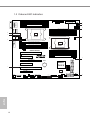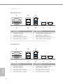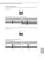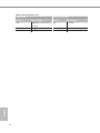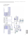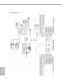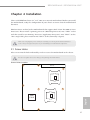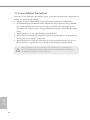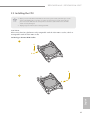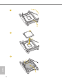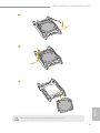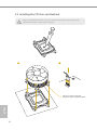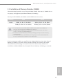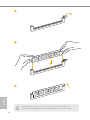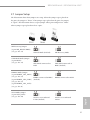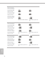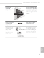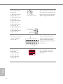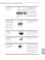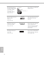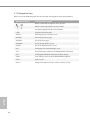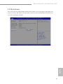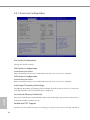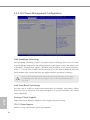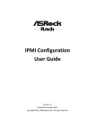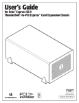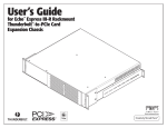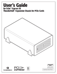
1
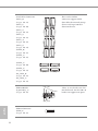
Version 1.1
Published November 2014
Copyright©2014 ASRock Rack Inc. All rights reserved.
Copyright Notice:
No part of this documentation may be reproduced, transcribed, transmitted, or
translated in any language, in any form or by any means, except duplication of
documentation by the purchaser for backup purpose, without written consent of
ASRock Rack Inc.
Products and corporate names appearing in this documentation may or may not
be registered trademarks or copyrights of their respective companies, and are used
only for identiication or explanation and to the owners’ beneit, without intent to
infringe.
Disclaimer:
Speciications and information contained in this documentation are furnished
for informational use only and subject to change without notice, and should not
be constructed as a commitment by ASRock Rack. ASRock Rack assumes no
responsibility for any errors or omissions that may appear in this documentation.
With respect to the contents of this documentation, ASRock Rack does not provide
warranty of any kind, either expressed or implied, including but not limited to
the implied warranties or conditions of merchantability or itness for a particular
purpose.
In no event shall ASRock Rack, its directors, oicers, employees, or agents be liable
for any indirect, special, incidental, or consequential damages (including damages
for loss of proits, loss of business, loss of data, interruption of business and the
like), even if ASRock Rack has been advised of the possibility of such damages
arising from any defect or error in the documentation or product.
his device complies with Part 15 of the FCC Rules. Operation is subject to the following
two conditions:
(1) this device may not cause harmful interference, and
(2) this device must accept any interference received, including interference that
may cause undesired operation.
CALIFORNIA, USA ONLY
he Lithium battery adopted on this motherboard contains Perchlorate, a toxic substance
controlled in Perchlorate Best Management Practices (BMP) regulations passed by the
California Legislature. When you discard the Lithium battery in California, USA, please
follow the related regulations in advance.
“Perchlorate Material-special handling may apply, see www.dtsc.ca.gov/hazardouswaste/
perchlorate”
ASRock Rack’s Website: www.ASRockRack.com
Contact Information
If you need to contact ASRock Rack or want to know more about ASRock Rack,
you’re welcome to visit ASRock Rack’s website at www.ASRockRack.com; or you
may contact your dealer for further information.
ASRock Rack Incorporation
6F., No.37, Sec. 2, Jhongyang S. Rd., Beitou District,
Taipei City 112, Taiwan (R.O.C.)
Contents
Chapter 1 Introduction
1
1.1
Package Contents
1
1.2
Speciications
2
1.3
Unique Features
6
1.4
Motherboard Layout
7
1.5
Onboard LED Indicators
10
1.6
I/O Panel
12
1.7
Block Diagram
15
Chapter 2 Installation
17
2.1
Screw Holes
17
2.2
Pre-installation Precautions
18
2.3
Installing the CPU
19
2.4
Installing the CPU Fan and Heatsink
22
2.5
Installation of Memory Modules (DIMM)
23
2.6
Expansion Slots (PCI and PCI Express Slots)
26
2.7
Jumper Setup
27
2.8
Onboard Headers and Connectors
30
2.9
Driver Installation Guide
37
2.10
Dual LAN and Teaming Operation Guide
38
Chapter 3 UEFI Setup Utility
39
3.1
Introduction
39
3.1.1
UEFI Menu Bar
39
3.1.2 Navigation Keys
40
3.2
Main Screen
41
3.3
Advanced Screen
42
3.3.1 ACPI Coniguration
43
3.3.2 Conigure Super IO Settings
44
3.3.3 Serial Port Console Redirection
45
3.3.4 CSM Parameters
48
3.3.5 USB Coniguration
49
3.3.6 System Coniguration
50
3.3.7 Hard Disk S.M.A.R.T Settings
52
3.3.7 3rd Storage Coniguration
53
3.3.8 H/W Monitor
54
3.3.9 Intel® Thunderbolt
56
3.3.10 Easy RAID Installer
57
3.3.11 Instant Flash
58
3.4
59
IntelRCSetup
3.4.1 Processor Coniguration
60
3.4.2 CPU Power Management Coniguration
62
3.4.3 QPI Coniguration
64
3.4.4 Memory Coniguration
65
3.4.5 IIO Coniguration
66
3.4.6 PCH Coniguration
68
3.4.7 Server ME Coniguration
70
3.5
Server Mgmt
71
3.6
Security
74
3.7
Boot Screen
75
3.8
Event Logs
77
3.9
Exit Screen
79
Chapter 4 Software Support
80
4.1
Install Operating System
80
4.2
Support CD Information
80
4.2.1 Running The Support CD
80
4.2.2 Drivers Menu
80
4.2.3 Utilities Menu
80
4.2.4 Contact Information
80
Chapter 5 Troubleshooting
81
5.1
Troubleshooting Procedures
81
5.2
Technical Support Procedures
83
5.3
Returning Merchandise for Service
83
Chapter 6: Net Framework Installation Guide
84
6.1
84
Installing .Net Framework 3.5.1 (For Server 2008 R2)
EP2C612D16-4L / EP2C612D16-2L2T
Chapter 1 Introduction
hank you for purchasing ASRock Rack EP2C612D16-4L / EP2C612D16-2L2T
motherboard, a reliable motherboard produced under ASRock Rack’s consistently
stringent quality control. It delivers excellent performance with robust design
conforming to ASRock Rack’s commitment to quality and endurance.
In this manual, chapter 1 and 2 contains introduction of the motherboard and stepby-step guide to the hardware installation. Chapter 3 and 4 contains the coniguration
guide to BIOS setup and information of the Support CD.
Because the motherboard speciications and the BIOS sotware might be updated, the content of this manual will be subject to change without notice. In case any modiications of
this manual occur, the updated version will be available on ASRock Rack website without
further notice. You may ind the latest memory and CPU support lists on ASRock Rack
website as well. ASRock Rack’s Website: www.ASRockRack.com
If you require technical support related to this motherboard, please visit our website for
speciic information about the model you are using.
http://www.asrockrack.com/support/
1.1 Package Contents
• ASRock Rack EP2C612D16-4L / EP2C612D16-2L2T Motherboard
(SSI EEB Form Factor: 12.0-in x 13.0-in, 30.5 cm x 33.0 cm)
• 4 x SATA3 Cables (50cm)
• 2 x SATA3 Cables (60cm)
• 1 x I/O Shield
• Support CD
• User Manual
English
If any items are missing or appear damaged, contact your authorized dealer.
1
1.2 Speciications
EP2C612D16-4L / EP2C612D16-2L2T
MB Physical Status
Form Factor
SSI EEB
Dimension
12'' x 13'' (30.5 cm x 33.0 cm)
Processor System
CPU
Socket
Chipset
System Memory
Capacity
Type
Intel® Xeon processor E5-2600/4600 v3 series
Dual Socket LGA 2011 R3
Intel® C612
16 DIMM slots
- Quad Channel DDR4 memory technology
- Supports 2133/1866/1600 ECC DIMM,RDIMM,NVDIMM
and LRDIMM
1.2V
Voltage
Expansion Slot (Slot 6 is the closest to the CPU)
Slot 1
x8 (x8/x8 with Slot 2, CPU2)
Slot 2
x16 (CPU2)
Slot 3
x8 (x8/x8 with Slot 4)
Only PCIE 3 slot supports the hunderbolt Add-in Card.
he hunderbolt Add-in Card is only supported on Windows 8 / 7.
Slot 4
Slot 5
Slot 6
Storage
SATA
Controller
Additional
SATA
Controller
English
2
x16
x8 (CPU2)
x16
Intel® C612 : 6 x SATA3 6.0Gb/s; 4 x sSATA3 6.0Gb/s; support
RAID 0, 1, 5, 10
Marvell 9172: 2 x SATA3 6Gb/s
EP2C612D16-4L / EP2C612D16-2L2T
Ethernet
Interface
EP2C612D16-2L2T:
10G by Intel X540 ; 1000 /100 /10 Mbps by Intel i210
EP2C612D16-4L:
1000 /100 /10 Mbps by Intel i350 / Intel i210
LAN
EP2C612D16-2L2T:
2 x RJ45 GLAN by Intel® i210
2 x RJ45 10G base-T by Intel® X540*
1 x RJ45 Dedicated IPMI LAN port
- Supports Wake-On-LAN
- Supports Energy Eicient Ethernet 802.3az
- Supports Quad LAN with Teaming function
- Supports PXE
- LAN1 supports NCSI
EP2C612D16-4L:
2 x RJ45 GLAN by Intel® i210
2 x RJ45 GLAN by Intel® i350
1 x RJ45 Dedicated IPMI LAN port
- Supports Wake-On-LAN
- Supports Energy Eicient Ethernet 802.3az
- Supports Dual LAN with Teaming function
- Supports PXE
- LAN1 supports NCSI
Graphics
Controller
VRAM
Rear Panel I/O
VGA Port
USB 3.0 Port
Lan Port
Serial Port
ASPEED AST2400
- 1 x Realtek RTL8211E for dedicated management GLAN
- Watch Dog
- NMI
ASPEED AST2400
DDR3 16MB
1 x D-Sub
2
- 4 + 1 (IPMI) Lan port (RJ45)
- LAN Ports with LED (ACT/LINK LED and SPEED LED)
1 (COM1)
English
Management
BMC Controller
IPMI Dedicated
GLAN
Features
3
Internal Connector
Auxiliary Panel 1 (includes chassis intrusion, location button & LED, front
Header
LAN LED and system event LED)
TPM Header
1
IPMB Header
1
Fan Header
2x CPU Fan, 6x system Fan (4-pin)
ATX Power
1 (24-pin) + 2 (8-pin)
USB 3.0 Header 1 ( support 2 USB 3.0)
USB 2.0 Header 1 ( support 2 USB 2.0)
Type A USB 3.0 1
Port
hunderbolt
1
AIC Connector
System BIOS
BIOS Type
128Mb AMI UEFI Legal BIOS
BIOS Features
- Plug and Play (PnP)
- ACPI 2.0 Compliance Wake Up Events
- SMBIOS 2.8 Support
- ASRock Rack Instant Flash
Hardware Monitor
Temperature
- CPU Temperature Sensing
- System Temperature Sensing
- Card Side Temperature Sensing
Fan
- CPU/Rear/Front Fan Tachometer
- CPU Quiet Fan (Allow CPU Fan Speed Auto-Adjust by CPU
Temperature)
- CPU/Rear/Front Fan Multi-Speed Control
Voltage
Voltage Monitoring: +12V, +5V, +3.3V, CPU Vcore, DRAM,
1.05V_PCH, +BAT, 3VSB, 5VSB
English
4
EP2C612D16-4L / EP2C612D16-2L2T
Support OS
OS
Microsot® Windows®
- Server 2008 R2 SP1 (64 bit)
- Server 2012 (64 bit)
- Server 2012 R2 (64 bit)
Linux®
- RedHat Enterprise Linux Server 5.10/6.5 (32 / 64 bit)
- CentOS 5.10 / 6.5 (32 / 64 bit)
- SUSE Enterprise Linux Server 11 SP3 (32 / 64 bit)
- FreeBSD 9.1 (32 / 64 bit)
- Fedora core 19 (64 bit)
- Ubuntu 12.04.2 (64 bit) / 12.10 (64 bit)
Virtual
- VMWare® ESXi 5.5 (not supported for Marvell 9172)
Environment
Temperature
Operation temperature: 10°C ~ 35°C / Non operation
temperature: -40°C ~ 70°C
* System air-low is required for cooling the onboard Intel Ethernet Controller X540 heat sink.
his motherboard supports Wake from on Board LAN. To use this function, please make
sure that the “Wake on Magic Packet from power of state” is enabled in Device Manager >
Intel® Ethernet Connection I210 > Power Management. And the “PCI Devices Power On” is
enabled in UEFI SETUP UTILITY > Advanced > ACPI Coniguration. Ater that, onboard
LAN1&2 can wake up S5 under OS.
English
If you install Intel® LAN utility or Marvell SATA utility, this motherboard may fail Windows® Hardware Quality Lab (WHQL) certiication tests. If you install the drivers only, it
will pass the WHQL tests.
5
1.3 Unique Features
ASRock Rack Instant Flash is a BIOS lash utility embedded in Flash ROM. his convenient BIOS update tool allows you to update system BIOS without entering operating systems irst like MS-DOS or Windows®. With this utility, you can press the <F6>
key during the POST or the <F2> key to enter into the BIOS setup menu to access
ASRock Rack Instant Flash. Just launch this tool and save the new BIOS ile to your
USB lash drive, loppy disk or hard drive, then you can update your BIOS only in a
few clicks without preparing an additional loppy diskette or other complicated lash
utility. Please be noted that the USB lash drive or hard drive must use FAT32/16/12
ile system.
English
6
EP2C612D16-4L / EP2C612D16-2L2T
1.4 Motherboard Layout
EP2C612D16-2L2T / EP2C612D16-4L
1 2
3
5
4
6
7
33.0cm (13.0 in)
IPMB_1
DDR4_G1 (64 bit, 288-pin module, Blue)
1
1
ATXPWR1
PSU_SMB1
DDR4_G2 (64 bit, 288-pin module, White )
ATX12V3
8
FRNT_FAN2
COM1
VGA1
DDR4_H1 (64 bit, 288-pin module, Blue)
9
FRNT_FAN1
10
DDR4_H2 (64 bit, 288-pin module, White )
DDR4_A1 (64 bit, 288-pin module, Blue )
LAN2
LAN1
ATX12V2
11
DDR4_A2 (64 bit, 288-pin module, White)
DDR4_B1 (64 bit, 288-pin module, Blue)
12
60
DDR4_B2 (64 bit, 288-pin module, White )
USB 3.0
T: USB1
B: USB2
IPMI_LAN
59
CPU2
13
REAR_FAN1
CPU1_FAN1
LAN3
58
CPU2_FAN2
REAR_FAN2
DDR4_F2 (64 bit, 288-pin module, White)
57
14
DDR4_E2 (64 bit, 288-pin module, White)
30.5cm (12.0 in)
LAN4
DDR4_F1 (64 bit, 288-pin module, Blue)
CPU1
DDR4_E1 (64 bit, 288-pin module, Blue)
1
T B1
5 6
EP2C612D16-4L
55
DDR4_D2 (64 bit, 288-pin module, White )
15
DDR4_D1 (64 bit, 288-pin module, Blue)
PCIE6 (Blue)
DDR4_C2 (64 bit, 288-pin module, White )
Super
I/O
16
DDR4_C1 (64 bit, 288-pin module, Blue)
PCIE5 (White)
17
18
19
20
21
FRNT_FAN3
PCIE2
SATA_SGPIO1
SATA_0
22
23
SATA_2
SATA_3
Intel
C612
BATTERY1
24
25
1
(White)
SATA_5
PCIE3 (Blue)
SATA_1
RoHS
SATA_4
PCIE4 (Blue)
1
SATA_SGPIO2
26
27
1
SSATA_SGPIO1
BMC
ROM
BIOS
64Mb
54
1
1
NCSI_SEL1
1
1
SSATA_0
28
SPEAKER1
CHASSIS_ID2
FRONT_LAN_3_4 CHASSIS_ID0
CHASSIS_ID1
1
NMI_BTN1
1
1
1
1
1
29
1
BMC_SMB_2
BMC_SMB_1
USB_1_2
USB3_3_4
PANEL1
AUX_PANEL1
ME_RECOVERY1 M_SATA_0
SSATA_2
M_SATA_1
SSATA_3
PLED PWRBTN
FRNT_FAN4
1
PECI1
53 52 51 50 49 48 47 4645 44 43
1
1
1
42
41
1
1
HDLED RESET
TPM1
40
39
38
37
36
35
34
33 32
31 30
English
PMBUS_SEL_DAT1
PMBUS_SEL_CLK1
PMBUS_SEL_ALT1
PCIE_PWR1
SSATA_1
USB3_5
PCIE1 (White)
7
No.
English
8
Description
1
2 x 288-pin DDR4 DIMM Slots (DDR4_G2, DDR4_H2, White)
2
2 x 288-pin DDR4 DIMM Slots (DDR4_G1, DDR4_H1, Blue)
3
LGA 2011-3 CPU Socket (CPU2)
4
Intelligent Platform Management Bus header (IPMB_1)
5
ATX 12V Power Connector (ATX12V3)
6
PSU SMBus (PSU_SMB1)
7
ATX Power Connector (ATXPWR1)
8
Front Fan Connector (FRNT_FAN2)
9
Front Fan Connector (FRNT_FAN1)
10
ATX 12V Power Connector (ATX12V2)
11
2 x 288-pin DDR4 DIMM Slots (DDR4_A1, DDR4_B1, Blue)
12
2 x 288-pin DDR4 DIMM Slots (DDR4_A2, DDR4_B2, White)
13
CPU1 Fan Connector (CPU1_FAN1)
14
LGA 2011-3 CPU Socket (CPU1)
15
2 x 288-pin DDR4 DIMM Slots (DDR4_C2, DDR4_D2, White)
16
2 x 288-pin DDR4 DIMM Slots (DDR4_C1, DDR4_D1, Blue)
17
Front Fan Connector (FRNT_FAN3)
18
SATA SGPIO Connector (SATA_SGPIO1)
19
SATA SGPIO Connector (SATA_SGPIO2)
20
SATA3 Connector (SATA_1), White
21
SATA3 Connector (SATA_0), White
22
SATA3 Connector (SATA_3), White
23
SATA3 Connector (SATA_2), White
24
SATA3 Connector (SATA_5), White
25
SATA3 Connector (SATA_4), White
26
SATA3 Connector (SSATA_1), White
27
SATA3 Connector (SSATA_0), White
28
SSATA SGPIO Connector (SSATA_SGPIO1)
29
Front Fan Connector (FRNT_FAN4)
30
SATA3 Connector (SSATA_2), White
31
SATA3 Connector (SSATA_3), White
32
SATA3 Connector (M_SATA_0), White
33
SATA3 Connector (M_SATA_1), White
EP2C612D16-4L / EP2C612D16-2L2T
No.
Description
34
ME Recovery Jumper (ME_RECOVERY1)
35
Speaker Header (SPEAKER1)
36
USB 2.0 Header (USB_1_2)
37
Vertical Type A USB 3.0 (USB3_5)
38
USB 3.0 Header (USB3_3_4)
39
System Panel Header (PANEL1)
40
Auxiliary Panel Header (AUX_PANEL1)
41
BMC SMBus Header (BMC_SMB_1)
42
TPM Header (TPM1)
43
BMC SMBus Header (BMC_SMB_2)
44
CPU PECI Mode Jumper (PECI1)
45
Non Maskable Interrupt Button (NMI_BTN1)
46
Chassis ID1 Jumper (Chassis ID1)
47
Chassis ID0 Jumper (Chassis ID0)
48
Front Lan LED Connector (FRONT_LAN_3_4)
49
Chassis ID2 Jumper (Chassis ID2)
50
NCSI Mode Jumper (NCSI_SEL1)
51
PMBUS Mode Jumper (PMBUS_SEL_ALT1)
52
PMBUS Mode Jumper (PMBUS_SEL_CLK1)
53
PMBUS Mode Jumper (PMBUS_SEL_DAT1)
54
PCIE Power Connector (PCIE_PWR1)
55
hunderbolt Connector (TB1)
56
2 x 288-pin DDR4 DIMM Slots (DDR4_E1, DDR4_F1, Blue)
57
2 x 288-pin DDR4 DIMM Slots (DDR4_E2, DDR4_F2, White)
58
Rear Fan Connector (REAR_FAN2)
59
Rear Fan Connector (REAR_FAN1)
60
CPU 2 Fan Connector (CPU2_FAN2)
English
*For DIMM installation and coniguration instructions, please see p.22 (Installation of Memory Modules
(DIMM)) for more details.
**Only PCIE 3 slot supports the hunderbolt Add-in Card. he hunderbolt Add-in Card is only supported on
Windows 8 / 7.
9
1.5 Onboard LED Indicators
DDR4_G1 (64 bit, 288-pin module, Blue)
1
ATXPWR1
FAN_LED2
DDR4_G2 (64 bit, 288-pin module, White )
1
SB_PWR1
COM1
VGA1
2
DDR4_H1 (64 bit, 288-pin module, Blue)
FAN_LED1
DDR4_H2 (64 bit, 288-pin module, White )
LAN2
LAN1
3
DDR4_A1 (64 bit, 288-pin module, Blue )
DDR4_A2 (64 bit, 288-pin module, White)
DDR4_B1 (64 bit, 288-pin module, Blue)
10
DDR4_B2 (64 bit, 288-pin module, White )
USB 3.0
T: USB1
B: USB2
IPMI_LAN
9
FAN_LED5
4
CPU2
FAN_LED6
8
LAN3
FAN_LED4
DDR4_F2 (64 bit, 288-pin module, White)
LAN4
DDR4_F1 (64 bit, 288-pin module, Blue)
DDR4_E2 (64 bit, 288-pin module, White)
CPU1
DDR4_E1 (64 bit, 288-pin module, Blue)
1
EP2C612D16-4L
DDR4_D2 (64 bit, 288-pin module, White )
DDR4_D1 (64 bit, 288-pin module, Blue)
PCIE6 (Blue)
DDR4_C2 (64 bit, 288-pin module, White )
Super
I/O
DDR4_C1 (64 bit, 288-pin module, Blue)
PCIE5
(White)
5
FAN_LED7
PCIE4 (Blue)
RoHS
PCIE3 (Blue)
Intel
C612
BATTERY1
BMC_LED1
7
PCIE2
(White)
1
1
1
USB3_5
PCIE1 (White)
FAN_LED8
1
BIOS
64Mb
1
1
1
1
1
English
10
6
PLED PWRBTN
1
1
1
1
1
1
HDLED RESET
1
EP2C612D16-4L / EP2C612D16-2L2T
Status
Description
1
Amber
FRNT_FAN2 failed
2
Amber
FRNT_FAN1 failed
3
Green
STB PWR ready
4
Amber
CPU1_FAN1 failed
5
Amber
FRNT_FAN3 failed
6
Amber
FRNT_FAN4 failed
7
Green
BMC heartbeat LED
8
Amber
CPU2_FAN1 failed
9
Amber
Rear_FAN2 failed
10
Amber
Rear_FAN1 failed
English
No.
11
1.6 I/O Panel
EP2C61216D-2L2T
1
3
5
2
4
6
7
No. Description
No. Description
1
5
Serial Port (COM1)
8
LAN RJ-45 Port (IPMI_LAN)*
2
VGA Port (VGA1)
6
USB 3.0 Ports (USB3_1_2)
3
GLAN RJ-45 Port (LAN2)**
7
10G LAN RJ-45 Port (LAN3)**
4
GLAN RJ-45 Port (LAN1)**
8
10G LAN RJ-45 Port (LAN4)**
* System air-low is required for cooling the onboard Intel Ethernet Controller X540 heat sink.
EP2C61216D-4L
1
3
5
2
4
6
No. Description
English
12
7
8
No. Description
1
Serial Port (COM1)
5
LAN RJ-45 Port (IPMI_LAN)*
2
VGA Port (VGA1)
6
USB 3.0 Ports (USB3_1_2)
3
GLAN RJ-45 Port (LAN2)**
7
GLAN RJ-45 Port (LAN3)**
4
GLAN RJ-45 Port (LAN1)**
8
GLAN RJ-45 Port (LAN4)**
EP2C612D16-4L / EP2C612D16-2L2T
LAN Port LED Indications
*here are two LED next to the LAN port. Please refer to the table below for the LAN port
LED indications.
ACT/LINK LED
SPEED LED
LAN Port
Dedicated IPMI / LAN1 / LAN2 LAN Port LED Indications
Activity / Link LED
Speed LED
Status
Description
Status
Description
Of
Blinking Yellow
On
No Link
Data Activity
Link
Of
Of
Yellow
Green
No Link
10M bps connection
100M bps connection
1G bps connection
**here are two LEDs on each LAN port. Please refer to the table below for the LAN port
LED indications.
SPEED LED
ACT/LINK LED
LAN Port
LAN Port (LAN3, LAN4) LED Indications
1G For EP2C612D16-4L
Activity / Link LED
Status
Description
Status
Description
Of
10Mbps connection or
no link
100Mbps connection
1Gbps connection
Of
No Link
Blinking Green
On
Data Activity
Link
Yellow
Green
English
Speed LED
13
10G For EP2C612D16-2L2T
Speed LED
Description
Of
100Mbps connection or Of
no link
1Gbps connection
Blinking Green
10Gbps connection
On
Yellow
Green
English
14
Activity / Link LED
Status
Status
Description
No Link
Data Activity
Link
EP2C612D16-4L / EP2C612D16-2L2T
1.7 Block Diagram
English
EP2C61216D-2L2T
15
EP2C61216D-4L
English
16
EP2C612D16-4L / EP2C612D16-2L2T
Chapter 2 Installation
his is a SSI EEB form factor (12'' x 13'', 30.5 cm x 33.0 cm) motherboard. Before you install
the motherboard, study the coniguration of your chassis to ensure that the motherboard
its into it.
EP2C612 Series are dual socket motherboards that support Intel® Xeon® E5-2600 v3 Series
Processors. Please install a primary processor (BootStrap Processor) into “CPU1” socket
and then install a non-Primary Processor (Application Processors) into “CPU2” socket.
*For a single CPU, please install it into “CPU1” socket (framed by a square).
Make sure to unplug the power cord before installing or removing the motherboard. Failure
to do so may cause physical injuries to you and damages to motherboard components.
2.1 Screw Holes
Place screws into the holes indicated by circles to secure the motherboard to the chassis.
Do not over-tighten the screws! Doing so may damage the motherboard.
Screw Holes Location
Rear I/O
English
Intel
C612
17
2.2 Pre-installation Precautions
Take note of the following precautions before you install motherboard components or
change any motherboard settings.
1. Unplug the power cord from the wall socket before touching any components.
2. To avoid damaging the motherboard’s components due to static electricity, NEVER
place your motherboard directly on the carpet or the like. Also remember to use a
grounded wrist strap or touch a safety grounded object before you handle the components.
3. Hold components by the edges and do not touch the ICs.
4. Whenever you uninstall any component, place it on a grounded anti-static pad or in
the bag that comes with the component.
5. When placing screws into the screw holes to secure the motherboard to the chassis,
please do not over-tighten the screws! Doing so may damage the motherboard.
Before you install or remove any component, ensure that the power is switched of or the
power cord is detached from the power supply. Failure to do so may cause severe damage to
the motherboard, peripherals, and/or components.
English
18
EP2C612D16-4L / EP2C612D16-2L2T
2.3 Installing the CPU
1. Before you insert the 2011-3-Pin CPU into the socket, please check if the PnP cap is on the
socket, if the CPU surface is unclean, or if there are any bent pins in the socket. Do not
force to insert the CPU into the socket if above situation is found. Otherwise, the CPU
will be seriously damaged.
2. Unplug all power cables before installing the CPU.
CAUTION:
Please note that C612 platform is only compatible with the LGA 2011-3 socket, which is
incompatible with the LGA 2011 socket
Socket Type: Narrow ILM Socket
1
A
B
A
2
English
B
19
3
A
B
4
5
English
20
EP2C612D16-4L / EP2C612D16-2L2T
6
A
B
7
A
B
English
8
he cover must be placed if returning the motherboard for ater service.
21
2.4 Installing the CPU Fan and Heatsink
Before you installed the heatsink, you need to spray thermal interface material between the
CPU and the heatsink to improve heat dissipation.
2
CP
U_
FA
N
1
CPU fan for narrow ILM socket
*Support an active or passive heatsink
English
22
EP2C612D16-4L / EP2C612D16-2L2T
2.5 Installation of Memory Modules (DIMM)
his motherboard provides sixteen 288-pin DDR4 (Double Data Rate 4) DIMM slots in
two groups, and supports Quad Channel Memory Technology.
You may install RDIMMs, LR-DIMMs and NVDIMMs into the sockets.
Capacity
CPU1
CPU2
256GB
DDR4_A1, B1, C1, D1 (Blue)
DDR4_E1, F1, G1, H1 (Blue)
DDR4_A2, B2, C2, D2 (White)
DDR4_E2, F2, G2, H2 (White)
1. It is not allowed to install a DDR, DDR2 or DDR3 memory module into a DDR4 slot;
otherwise, this motherboard and DIMM may be damaged.
2. For quad channel coniguration, you always need to install identical (the same brand,
speed, size and chip-type) DDR4 DIMM pairs.
3. It is unable to activate Dual Channel Memory Technology with only one or three memory
module installed.
4. Some DDR4 1GB double-sided DIMMs with 16 chips may not work on this motherboard.
It is not recommended to install them on this motherboard.
English
If only two memory modules are installed in the DDR4 DIMM slots, then Dual Channel
Memory Technology is activated. If three memory modules are installed, then Triple
Channel Memory Technology is activated. If more than four memory modules are
installed in the DDR4 DIMM slots, then Quad Channel Memory Technology is activated.
23
1
2
3
English
he DIMM only its in one correct orientation. It will cause permanent damage to the
motherboard and the DIMM if you force the DIMM into the slot at incorrect orientation.
24
EP2C612D16-4L / EP2C612D16-2L2T
Recommended Memory Conigurations
A single memory module should be installed in the BLUE socket.
If you install only one CPU (CPU1) on the motherboard, make sure to install
DIMMs into DDR4_A, DDR4_B, DDR4_C, or DDR4_D slot(s).
Memory can speed up to 2133 MHz for 1 DIMM per channel. For two DIMMs per channel,
memory speed should be 1866MHz.
1 CPU Coniguration
CPU1
A1
A2
B1
1 DIMM
#
2 DIMMS
#
#
4 DIMMS
#
#
8 DIMMS
#
#
#
B2
C1
C2
#
#
D1
D2
#
#
#
#
#
C1
C2
D1
D2
*he # mark indicates the slot is populated.
2 CPU Coniguration
CPU1
A1
A2
B1
B2
1 DIMM
#
2 DIMMS
#
#
4 DIMMS
#
#
#
#
8 DIMMS
#
#
#
#
12 DIMMS
#
#
#
#
#
#
#
#
16 DIMMS
#
#
#
#
#
#
#
#
G1
G2
H1
H2
CPU2
E1
E2
F1
F2
1 DIMM
English
2 DIMMS
4 DIMMS
8 DIMMS
#
#
#
#
12 DIMMS
#
#
#
#
16 DIMMS
#
#
#
#
#
#
#
#
25
2.6 Expansion Slots (PCI and PCI Express Slots)
here are 6 PCI Express slots on this motherboard.
PCIE slot:
PCIE5 (PCIE 3.0 x8 slot, from CPU 2) is used for PCI Express x8 lane width graphics cards.
PCIE3 (PCIE 3.0 x8 slot, from CPU 1) is used for PCI Express x8 lane width graphics cards.
PCIE1 (PCIE 3.0 x8 slot, from CPU 2) is used for PCI Express x8 lane width graphics cards.
PCIE4 and PCIE6 (PCIE 3.0 x16 slot, from CPU 1) are used for PCI Express x16 lane width
graphics cards.
PCIE2 (PCIE 3.0 x16 slot, from CPU 2) is used for PCI Express x16 lane width graphics
cards.
Slot
Generation
Mechanical
PCIE 6
3.0
PCIE 5
3.0
PCIE 4
3.0
PCIE 3*
3.0
PCIE 2
3.0
PCIE 1
3.0
x8
Electrical
x16
Source
x16
CPU 1
x8
x8
CPU 2
x16
x16
CPU 1
x8
x8
CPU 1
x16
x16
CPU 2
x8
CPU 2
*Only PCIE 3 slot supports the hunderbolt Add-in Card. he hunderbolt Add-in Card is only supported on
Windows 8 / 7.
PCI Express Slot Coniguration
PCIE 1
Single Graphics Card
Two Graphics Cards
No.
x16
x8
PCIE 3
Single Graphics Card
Two Graphics Cards
English
26
PCIE 2
x8
PCIE 4
x16
x8
x8
EP2C612D16-4L / EP2C612D16-2L2T
2.7 Jumper Setup
ME Recovery Jumper
(3-pin ME_RECOVERY1)
(see p.7, No. 34)
CPU PECI Mode Jumper
(3-pin PECI1)
(see p.7, No. 44)
PMBUS Mode Jumper
(3-pin PMBUS_SEL_DAT1)
(see p.7, No. 53)
(3-pin PMBUS_SEL_CLK1)
(see p.7, No. 52)
(3-pin PMBUS_SEL_ALT1)
(see p.7, No. 51)
NCSI Mode Jumper
(3-pin NCSI_SEL1)
(see p.7, No. 50)
Normal Mode (Default)
ME Recovery Mode
CPU PECI connected to
PCH
CPU PECI connected to
BMC (Default)
PMBus connected to BMC
(Default)
PMBus connected to PCH
NCSI is set to onboard
LAN1 (Default)
NCSI is set to onboard
LAN4
English
he illustration shows how jumpers are setup. When the jumper cap is placed on
the pins, the jumper is “Short”. If no jumper cap is placed on the pins, the jumper
is “Open”. he illustration shows a 3-pin jumper whose pin1 and pin2 are “Short”
when a jumper cap is placed on these 2 pins.
27
Chassis ID Jumper
Chassis ID0 Jumper
(3-pin Chassis ID0)
(see p.7, No. 47)
Chassis ID1 Jumper
(3-pin Chassis ID1 )
(see p.7, No. 46)
Chassis ID2 Jumper
(3-pin Chassis ID2)
(see p.7, No. 49)
English
28
Board Level SKU (Default)
Reserved for system level
use
Chassis ID0 Jumper
(3-pin Chassis ID0)
(see p.7, No. 47)
Chassis ID1 Jumper
(3-pin Chassis ID1 )
(see p.7, No. 46)
Chassis ID2 Jumper
(3-pin Chassis ID2)
(see p.7, No. 49)
Reserved for system level
use
Reserved for system level
use
Chassis ID0 Jumper
(3-pin Chassis ID0)
(see p.7, No. 47)
Chassis ID1 Jumper
(3-pin Chassis ID1 )
(see p.7, No. 46)
Chassis ID2 Jumper
(3-pin Chassis ID2)
(see p.7, No. 49)
Reserved for system level
use
Reserved for system level
use
EP2C612D16-4L / EP2C612D16-2L2T
Reserved for system level
use
Reserved for system level
use
English
Chassis ID0 Jumper
(3-pin Chassis ID0)
(see p.7, No. 47)
Chassis ID1 Jumper
(3-pin Chassis ID1 )
(see p.7, No. 46)
Chassis ID2 Jumper
(3-pin Chassis ID2)
(see p.7, No. 49)
29
2.8 Onboard Headers and Connectors
Onboard headers and connectors are NOT jumpers. Do NOT place jumper caps over these
headers and connectors. Placing jumper caps over the headers and connectors will cause
permanent damage to the motherboard.
PLED+
PLEDPWRBTN#
GND
System Panel Header
(9-pin PANEL1)
(see p.7, No. 39)
1
GND
RESET#
GND
HDLEDHDLED+
Con nec t t he power sw itch,
reset switch and system status
indicator on the chassis to this
header according to the pin
assignments. Particularly note
the positive and negative pins
before connecting the cables.
PWRBTN (Power Switch):
Connect to the power switch on the chassis front panel. You may conigure the way to turn
of your system using the power switch.
RESET (Reset Switch):
Connect to the reset switch on the chassis front panel. Press the reset switch to restart the
computer if the computer freezes and fails to perform a normal restart.
PLED (System Power LED):
Connect to the power status indicator on the chassis front panel. he LED is on when the
system is operating. he LED keeps blinking when the system is in S1/S3 sleep state. he
LED is of when the system is in S4 sleep state or powered of (S5).
HDLED (Hard Drive Activity LED):
Connect to the hard drive activity LED on the chassis front panel. he LED is on when the
hard drive is reading or writing data.
he front panel design may difer by chassis. A front panel module mainly consists of power
switch, reset switch, power LED, hard drive activity LED, speaker and etc. When connecting your chassis front panel module to this header, make sure the wire assignments and the
pin assignments are matched correctly.
English
30
EP2C612D16-4L / EP2C612D16-2L2T
LED_PWR
LAN2_LINK
System Fault LED-A
LAN1_LINK
LED_PWR
GND
+3VSB
LOCATORLED1-
GND
SMB_DATA
B
LOCATORLED1+
SMB_Alert
SMB_CLK
A
Auxiliary Panel Header
(18-pin AUX PANEL1)
(see p.7, No. 40)
C
D
System Fault LED+
LOCATORBTN#
GND
CASEOPEN
+5VSB
1
his header supports multiple
functions on the front panel,
including the front panel SMB,
internet status indicator and
chassis intrusion pin.
E
A. Front panel SMBus connecting pin (6-1 pin FPSMB)
his header allows you to connect SMBus (System Management Bus) equipment. It can
be used for communication between peripheral equipment in the system, which has slower
transmission rates, and power management equipment.
B. Internet status indicator (2-pin LAN1_LED, LAN2_LED)
hese two 2-pin headers allow you to use the Gigabit internet indicator cable to connect
to the LAN status indicator. When this indicator lickers, it means that the internet is properly connected.
C. Chassis intrusion pin (2-pin CHASSIS)
his header is provided for host computer chassis with chassis intrusion detection designs.
In addition, it must also work with external detection equipment, such as a chassis intrusion detection sensor or a microswitch. When this function is activated, if any chassis
component movement occurs, the sensor will immediately detect it and send a signal to this
header, and the system will then record this chassis intrusion event. he default setting is
set to the CASEOPEN and GND pin; this function is of.
D. Locator LED (4-pin LOCATOR)
his header is for the locator switch and LED on the front panel.
English
E. System Fault LED (2-pin LOCATOR)
his header is for the Fault LED on the system.
31
(SSATA_2)
(see p.7, No. 30)
(SSATA_3)
(see p.7, No. 31)
(M_SATA_0)
(see p.7, No. 32)
(M_SATA_1)
(see p.7, No. 33)
SA TA_0
M_SATA_1
SSATA_3
USB_PWR
P-7
P+7
GND
DUMMY
GND
P+6
P-6
USB_PWR
English
32
SA TA_2
SSATA_2
1
USB 3.0 Connector
(USB3_5)
(see p.7, No. 37)
SA TA _4
M_SATA_0
USB 2.0 Header
(9-pin USB_1_2)
(see p.7, No. 36)
hese twelve SATA3
connectors support SATA
data cables for internal storage
devices with up to 6.0 Gb/s
data transfer rate.
SSATA_0
SSATA_1
SA TA_5
SA TA_3
SA TA_1
Serial ATA3 Connectors
(SATA_0)
(see p.7, No. 21)
(SATA_1)
(see p.7, No. 20)
(SATA_2)
(see p.7, No. 23)
(SATA_3)
(see p.7, No. 22)
(SATA_4)
(see p.7, No. 25)
(SATA_5)
(see p.7, No. 24)
(SSATA_0)
(see p.7, No. 27)
(SSATA_1)
(see p.7, No. 26)
There is one header on t his
motherboard. Each USB 2.0
header can support two ports.
EP2C612D16-4L / EP2C612D16-2L2T
IntA_PA_D+
IntA_PA_DGND
IntA_PA_SSTX+
IntA_PA_SSTXGND
IntA_PA_SSRX+
IntA_PA_SSRXVbus
USB 3.0 Header
(19-pin USB3_3_4)
(see p.7, No. 38)
Besides two default USB 3.0
ports on the I/O panel, there
is one USB 3.0 header on this
motherboard. This USB 3.0
header can support two USB
3.0 ports.
1
Vbus
IntA_PB_SSRXIntA_PB_SSRX+
GND
IntA_PB_SSTXIntA_PBA_SSTX+
GND
IntA_PB_DIntA_PB_D+
Dummy
CPU Fan Connectors
(4-pin CPU1_FAN1)
(see p.7, No. 13)
(4-pin CPU2_FAN1)
(see p.7, No. 60)
DUMMY SPEAKER
1
+5V
1
2
3
4
DUMMY
GN D
+ 12V
CPU_ FAN_SPEED
FAN_SPEED_CONTROL
4
3
2
1
Please connect the chassis
speaker to this header.
his motherboard provides
two 4-Pin CPU fan (Quiet
Fan) connectors. If you plan
to connect a 3-Pin CPU fan,
please connect it to Pin 1-3.
GND
+12V
CPU_FAN_SPEED
FAN_SPEED_CONTROL
English
Chassis Speaker Header
(4-pin SPEAKER1)
(see p.7, No. 35)
33
Front and Rear Fan
Connectors
(4-pin FRNT_FAN1)
(see p.7, No. 9)
(4-pin FRNT_FAN2)
(see p.7, No. 8)
(4-pin FRNT_FAN3)
(see p.7, No. 17)
(4-pin FRNT_FAN4)
(see p.7, No. 29)
(4-pin REAR_FAN1)
(see p.7, No. 59)
(4-pin REAR_FAN2)
(see p.7, No. 58)
GND
+12V
FAN_SPEED
FAN_SPEED_CONTROL
FAN_SPEED_CONTROL
2
1
3V
3V
GND
5V
GND
5V
GND
PWROK_PS
5VSB
3V
12
1
24
13
4
5
8
GND
his motherboard provides a
24-pin ATX power connector.
To use a 20-pin ATX power
supply, please plug it along Pin
1 and Pin 13.
3V
+12V2
1
-12V
GND
PSON#
GND
GND
GND
N/A
5V
5V
5V
GND
English
34
3
+12V
12V
ATX 12V Power
Connectors
(8-pin ATX12V2)
(see p.7, No. 10)
(8-pin ATX12V3)
(see p.7, No. 5)
4
FAN_SPEED
GND
12V
ATX Power Connector
(24-pin ATXPWR1)
(see p.7, No. 7)
Please connect fan cables to the
fan connectors and match the
black wire to the ground pin.
All fans support Fan Control.
his motherboard provides
two 8-pin ATX 12V power
connectors.
EP2C612D16-4L / EP2C612D16-2L2T
SERIRQ#
F_CLKRUN#
S_PWRDWN#
GND
LAD2_L
LFRAME#_L
TPM_RST#
LAD1_L
SMB_DATA_MAIN
1
+3VSB
SCLOCK
SLOAD
GND
GND
Intelligent Platform
Management Bus header
(4-pin IPMB_1)
(see p.7, No. 4)
LAD0_L
Non Maskable Interrupt
Button Header
(NMI_BTN1)
(see p.7, No. 45)
+3V
PSU SMBus
(PSU_SMB1)
(see p.7, No. 6)
LAD3_L
CK_33M_TPM
Serial General Purpose
Input/Output Headers
(7-pin SATA_SGPIO1)
(see p.7, No. 18)
(7-pin SATA_SGPIO2)
(see p.7, No. 19)
(7-pin SSATA_SGPIO1)
(see p.7, No. 28)
his connector supports
Trusted Platform Module
(TPM) system, which can
securely store keys, digital
certiicates, passwords, and
data. A TPM system also helps
enhance network security,
protects digital identities, and
ensures platform integrity.
These headers support Serial
Li n k i nter face for onboa rd
SATA connections.
1
SDATAOUT
GND
ALERT
+3VSB
SMBCLK
1
SMBDATA
GND
GND
1
PSU SMBus monitors t he
status of the power supply, fan
and system temperature.
Please connect a NMI device
to this header.
CONTROL
IPMB_SDA
IPMB_SCL
GND
No Connect
This 4-pin connector is used
to provide a cabled base-board
or front panel connection for
value added features and 3rdparty add-in cards, such as
Emergency Management cards,
that provide management
features using the IPMB.
English
GND
SMB_CLK_MAIN
TPM Header
(17-pin TPM1)
(see p.7, No. 42)
35
Baseboard Management
Controller SMBus Headers
(5-pin BMC_SMB_1)
(see p.7, No. 41)
(5-pin BMC_SMB_2)
(see p.7, No. 43)
BMC_SMBDATA
GND
BMC_SMBCLK
Power
BMC_SMB_PRESENT_1_N
LAN4_LINK
LED_PWR
Front Lan LED Connector
(FRONT_LED_
LAN_3_4)
(see p.7, No. 48)
1
LAN3_LINK
LED_PWR
English
36
his 4-pin connector is used
for the front LAN status
indicator.
Please connect this connector
with a hard disk power
connector when two graphics
cards are installed on this
motherboard.
PCIE Power Connector
(4-pin PCIE_PWR1)
(see p.7, No. 54)
hunderbolt Connector
(5-pin TB1)
(see p.7, No. 55)
hese headers are used for the
SM BUS devices..
1
Please connect a hunderbolt™
add-in card to this connector
via the GPIO cable.
EP2C612D16-4L / EP2C612D16-2L2T
2.9 Driver Installation Guide
English
To install the drivers to your system, please insert the support CD to your optical
drive irst. hen, the drivers compatible to your system can be auto-detected and listed
on the support CD driver page. Please follow the order from top to bottom to install
those required drivers. herefore, the drivers you install can work properly.
37
2.10 Dual LAN and Teaming Operation Guide
Dual LAN with Teaming enabled on this motherboard allows two single
connections to act as one single connection for twice the transmission bandwidth,
making data transmission more efective and improving the quality of transmission
of distant images. Fault tolerance on the dual LAN network prevents network
downtime by transferring the workload from a failed port to a working port.
he speed of transmission is subject to the actual network environment or status even with
Teaming enabled.
Before setting up Teaming, please make sure whether your Switch (or Router)
supports Teaming (IEEE 802.3ad Link Aggregation). You can specify a preferred
adapter in Intel PROSet. Under normal conditions, the Primary adapter handles all
non-TCP/IP traic. he Secondary adapter will receive fallback traic if the primary
fails. If the Preferred Primary adapter fails, but is later restored to an active status,
control is automatically switched back to the Preferred Primary adapter.
Step 1
From Device Manager, open the properties of a team.
Step 2
Click the Settings tab.
Step 3
Click the Modify Team button.
Step 4
Select the adapter you want to be the primary adapter and click the Set Primary
button.
If you do not specify a preferred primary adapter, the sotware will choose an
adapter of the highest capability (model and speed) to act as the default primary. If
a failover occurs, another adapter becomes the primary. he adapter will, however,
rejoin the team as a non-primary.
English
38
EP2C612D16-4L / EP2C612D16-2L2T
Chapter 3 UEFI Setup Utility
3.1 Introduction
his section explains how to use the UEFI SETUP UTILITY to conigure your system. he
UEFI chip on the motherboard stores the UEFI SETUP UTILITY. You may run the UEFI
SETUP UTILITY when you start up the computer. Please press <F2> or <Del> during the
Power-On-Self-Test (POST) to enter the UEFI SETUP UTILITY; otherwise, POST will
continue with its test routines.
If you wish to enter the UEFI SETUP UTILITY ater POST, restart the system by pressing
<Ctrl> + <Alt> + <Delete>, or by pressing the reset button on the system chassis. You may
also restart by turning the system of and then back on.
Because the UEFI sotware is constantly being updated, the following UEFI setup screens
and descriptions are for reference purpose only, and they may not exactly match what you
see on your screen.
3.1.1 UEFI Menu Bar
he top of the screen has a menu bar with the following selections:
Item
Description
Main
To set up the system time/date information
Advanced
To set up the advanced UEFI features
IntelRCSetup
For Intel CPU and chipset settings
Server Mgmt
To manage the server
Security
To set up the security features
Boot
To set up the default system device to locate and load the
Operating System
Event Logs
For event log coniguration
Exit
To exit the current screen or the UEFI SETUP UTILITY
English
Use < > key or < > key to choose among the selections on the menu bar, and
then press <Enter> to get into the sub screen.
39
3.1.2 Navigation Keys
Please check the following table for the function description of each navigation key.
Navigation Key(s)
English
40
Function Description
/
Moves cursor let or right to select Screens
/
Moves cursor up or down to select items
+ / -
To change option for the selected items
<Tab>
Switch to next function
<Enter>
To bring up the selected screen
<PGUP>
Go to the previous page
<PGDN>
Go to the next page
<HOME>
Go to the top of the screen
<END>
Go to the bottom of the screen
<F1>
To display the General Help Screen
<F7>
Discard changes and exit the UEFI SETUP UTILITY
<F9>
Load optimal default values for all the settings
<F10>
Save changes and exit the UEFI SETUP UTILITY
<F12>
Print screen
<ESC>
Jump to the Exit Screen or exit the current screen
EP2C612D16-4L / EP2C612D16-2L2T
3.2 Main Screen
English
Once you enter the UEFI SETUP UTILITY, the Main screen will appear and display the
system overview. he Main screen provides system overview information and allows you
to set the system time and date.
41
3.3 Advanced Screen
In this section, you may set the conigurations for the following items: ACPI Coniguration, Conigure Super IO Settings, Serial Port Console Redirection, CSM Parameters, USB
Coniguration, System Coniguration, Hard Disk S.M.A.R.T Settings, 3rd Storage Coniguration, H/W Monitor, Intel(R) hunderbolt, Easy RAID Installer and Instant Flash.
Setting wrong values in this section may cause the system to malfunction.
English
42
EP2C612D16-4L / EP2C612D16-2L2T
3.3.1 ACPI Coniguration
PCIE Devices Power On
Use this item to enable or disable PCIE devices to turn on the system from the power-sotof mode.
Ring-In Power On
Use this item to enable or disable Ring-In signals to turn on the system from the powersot-of mode.
RTC Alarm Power On
English
Use this item to enable or disable RTC (Real Time Clock) to power on the system.
43
3.3.2 Conigure Super IO Settings
Serial Port 1 Coniguration
Use this item to conigure the onboard serial port 1.
Select and enter the "Serial Port 1 Coniguration" and you will see the followings:
Serial Port
Use this item to enable or disable the onboard serial port.
Serial Port Address
Use this item to select an optimal setting for Super IO device.
SOL Coniguration
Use this item to conigure the onboard SOL Port.
Select and enter the "SOL Coniguration" and you will see the followings:
Serial Port
Use this item to enable or disable the onboard serial port.
Serial Port Address
English
Use this item to select an optimal setting for Super IO device.
44
EP2C612D16-4L / EP2C612D16-2L2T
3.3.3 Serial Port Console Redirection
COM1
Console Redirection
Use this option to enable or disable Console Redirection. If this item is set to Enabled, you
can select a COM Port to be used for Console Redirection.
Console Redirection Settings
Use this option to conigure Console Redirection Settings, and specify how your computer
and the host computer to which you are connected exchange information.
Terminal Type
Option
Description
VT100
VT100+
VT-UTF8
ANSI
ASCII character set
Extended VT100 that supports color and function keys
UTF8 encoding is used to map Unicode chars onto 1 or more bytes
Extended ASCII character set
English
Use this item to select the preferred terminal emulation type for out-of-band management.
It is recommended to select [VT-UTF8].
45
Bits Per Second
Use this item to select the serial port transmission speed. The speed used in the host
computer and the client computer must be the same. Long or noisy lines may require lower
transmission speed. he options include [9600], [19200], [57600], [115200] and [38400].
Data Bits
Use this item to set the data transmission size. he options include [7] and [8] (Bits).
Parity
Use this item to select the parity bit. he options include [None], [Even], [Odd], [Mark] and
[Space].
Stop Bits
he item indicates the end of a serial data packet. he standard setting is [1] Stop Bit. Select
[2] Stop Bits for slower devices.
Flow Control
Use this item to set the f low control to prevent data loss from buffer overf low. When
sending data, if the receiving bufers are full, a "stop" signal can be sent to stop the data
low. Once the bufers are empty, a "start" signal can be sent to restart the low. Hardware
low uses two wires to send start/stop signals. he options include [None] and [Hardware
RTS/CTS].
VT-UTF8 Combo Key Support
Use this item to enable or disable the VT-UTF8 Combo Key Support for ANSI/VT100
terminals.
Recorder Mode
Use this item to enable or disable Recorder Mode to capture terminal data and send it as
text messages.
Resolution 100x31
Use this item to enable or disable extended terminal resolution support.
Legacy OS Redirection Resolution
Use this item to select the number of rows and columns used in legacy OS redirection.
Putty Keypad
Use this item to select Function Key and Keypad on Putty.
Redirection Ater BIOS POST
If the [BootLoader] is selected, legacy console redirection is disabled before booting to
legacy OS. If [Always Enabled] is selected, legacy console redirection is enabled for legacy
English
46
EP2C612D16-4L / EP2C612D16-2L2T
OS. he default value is [Always Enabled].
Serial Port for Out-of-Band Management/Windows Emergency
Management Services (EMS)
Console Redirection
Use this option to enable or disable Console Redirection. If this item is set to Enabled, you
can select a COM Port to be used for Console Redirection.
Console Redirection Settings
Use this option to conigure Console Redirection Settings, and specify how your computer
and the host computer to which you are connected exchange information.
Terminal Type
Use this item to select the preferred terminal emulation type for out-of-band management.
It is recommended to select [VT-UTF8].
Option
Description
VT100
VT100+
VT-UTF8
ANSI
ASCII character set
Extended VT100 that supports color and function keys
UTF8 encoding is used to map Unicode chars onto 1 or more bytes
Extended ASCII character set
Bits Per Second
Use this item to select the serial port transmission speed. The speed used in the host
computer and the client computer must be the same. Long or noisy lines may require lower
transmission speed. he options include [9600], [19200], [57600] and [115200].
Flow Control
Use this item to set the f low control to prevent data loss from buffer overf low. When
sending data, if the receiving bufers are full, a "stop" signal can be sent to stop the data
low. Once the bufers are empty, a "start" signal can be sent to restart the low. Hardware
low uses two wires to send start/stop signals. he options include [None], [Hardware RTS/
CTS], and [Sotware Xon/Xof].
Data Bits
Use this item to set the data transmission size. he standard setting is [8] (Bits).
Parity
English
Use this item to select the parity bit. he standard setting is [None].
Stop Bits
he item indicates the end of a serial data packet. he standard setting is [1] Stop Bit.
47
3.3.4 CSM Parameters
Boot Option Filter
his option controls Legacy/UEFI ROMs priority. here are three coniguration
options: [UEFI and Legacy],[Legacy only] and [UEFI only].
Launch Storage OpROM Policy
Select UEFI only to run those that support UEFI option ROM only. Select Legacy
only to run those that support legacy option ROM only. Select Do not launch to not
execute both legacy and UEFI option ROM.
English
48
EP2C612D16-4L / EP2C612D16-2L2T
3.3.5 USB Coniguration
Intel USB3.0 Mode
Use this item to select the mode of operation of Intel USB 3.0 controller.
Coniguration options: [Enabled], [Disabled], [Auto] and [Smart Auto]. If [Auto] is
selected, all USB ports work as USB3.0 ater boot to OS. If [Smart Auto] is selected,
all USB ports work as USB3.0 ater boot to OS and work as USB2.0 in deep sleep
stages.
Legacy USB Support
English
Use this option to enable or disable legacy support for USB devices. he default value is
[Enabled].
49
3.3.6 System Coniguration
Primary Graphics Adapter
Use this item to select the type and primary VGA in case of multiple video contorllers.
Onboard VGA
Use this to enable or disable the Onboard VGA function. he default value is [Auto].
Onboard LAN1
his allows you to enable or disable the Onboard LAN 1 feature.
Onboard LAN2
his allows you to enable or disable the Onboard LAN 2 feature.
Onboard LAN3 and LAN4
his allows you to enable or disable both the Onboard LAN 3 & LAN 4 features.
Above 4G Decoding
Enable or disable 64bit capable Devices to be decoded in Above 4G Address Space (only if
English
the system supports 64 bit PCI decoding).
50
EP2C612D16-4L / EP2C612D16-2L2T
Restore on AC/Power Loss
English
his allows you to set the power state ater an unexpected AC/power loss. If [Power Of]
is selected, the AC/power remains of when the power recovers. If [Power On] is selected,
the AC/power resumes and the system starts to boot up when the power recovers. If [Last
State] is selected, it will recover to the state before AC/power loss.
51
3.3.7 Hard Disk S.M.A.R.T Settings
Hard Disk S.M.A.R.T.
Use this item to enable or disable the S.M.A.R.T. (Self-Monitoring, Analysis, and
Reporting Technology) feature. Coniguration options: [Disabled] and [Enabled].
English
52
EP2C612D16-4L / EP2C612D16-2L2T
3.3.7 3rd Storage Coniguration
Marvell 9172 Controller
Enable or disable Marvell 9172 Controller.
Marvell 9172 Operation Mode
his item is for M_SATA ports. Use this to select Marvell SATA operation mode.
Coniguration options: [IDE Mode], [AHCI Mode] and [RAID Mode]. he default value is
[AHCI Mode].
Bootable Marvell 9172 SATA3
English
We recommend to use Intel SATA ports (Port 0~5) for your bootable devices. his will
minimize your boot time and get the best performance. If you still want to boot from
Marvell SATA3 controller, please set this item to Yes.
53
3.3.8 H/W Monitor
In this section, it allows you to monitor the status of the hardware on your system, including the parameters of the CPU temperature, motherboard temperature, CPU fan speed,
chassis fan speed, and the critical voltage.
CPU1_FAN1
his allows you to set the CPU1 fan’s speed. he default value is [Smart Fan].
CPU2_FAN1
his allows you to set the CPU2 fan’s speed. he default value is [Smart Fan].
REAR_FAN 1
his allows you to set the rear fan 1’s speed. he default value is [Smart Fan].
REAR_FAN 2
his allows you to set the rear fan 2’s speed. he default value is [Smart Fan].
FRNT_FAN 1
English
his allows you to set the front fan 1’s speed. he default value is [Smart Fan].
FRNT_FAN 2
his allows you to set the front fan 2’s speed. he default value is [Smart Fan].
54
EP2C612D16-4L / EP2C612D16-2L2T
FRNT_FAN 3
his allows you to set the front fan 3’s speed. he default value is [Smart Fan].
FRNT_FAN 4
his allows you to set the front fan 4’s speed. he default value is [Smart Fan].
Smart Fan Control
his allows you to set the Smart fan’s level speed.
Smart Fan Duty Control
Smart Fan Duty x (x means 1 to 11 stage)
his allows you to set duty cycle for each stage.
Smart Fan Temp Control
Smart Fan Temp x (x means 1 to 11 stage)
his allows you to set temperature for each stage.
Watch Dog Timer
English
his allows you to enable or disable, or conigure watch dog timer feature. he default
value is [Disabled].
Reset: System will reboot ater being idle for 5 minutes.
NMI: System will display blue screen ater boot to OS and being idle for 5 minutes.
System will display error message on the screen ater boot to DOS and being idle for 5
minutes.
55
3.3.9 Intel® Thunderbolt
Intel® Thunderbolt Technology
Enable or disable the Intel® hunderbolt™ function.
Security Level
Select Legacy to skip the Windows certiication checking process for hunderbolt™
devices. Select Unique ID for checking the Windows certiication, and show
warning messages if the devices aren't certiied. Or select DP++ to support DP 1.2.
Thunderbolt™ PCIe Cache-line Size
Conigure the cache-line size of the hunderbolt PCIe subtree.
English
56
EP2C612D16-4L / EP2C612D16-2L2T
3.3.10 Easy RAID Installer
English
Easy RAID Installer can help you to copy the RAID driver from a support CD to your USB
storage device. Ater copying the RAID driver to your USB storage device, please change
“SATA Mode” to “RAID”, then you can start installing the OS in RAID mode.
57
3.3.11 Instant Flash
Instant Flash is a UEFI lash utility embedded in Flash ROM. his convenient UEFI
update tool allows you to update system UEFI without entering operating systems
irst like MS-DOS or Windows®. Just save the new UEFI ile to your USB lash drive,
loppy disk or hard drive and launch this tool, then you can update your UEFI only
in a few clicks without preparing an additional loppy diskette or other complicated lash utility. Please be noted that the USB lash drive or hard drive must use
FAT32/16/12 ile system. If you execute Instant Flash utility, the utility will show the
UEFI iles and their respective information. Select the proper UEFI ile to update
your UEFI, and reboot your system ater the UEFI update process is completed.
English
58
EP2C612D16-4L / EP2C612D16-2L2T
3.4 IntelRCSetup
English
In this section, you may set the conigurations for the following items: Processor Coniguration, CPU Power Management Coniguration, QPI Coniguration, Memory Coniguration, IIO Coniguration, PCH Coniguration and Server ME Coniguration.
59
3.4.1 Processor Coniguration
Per-Socket Coniguration
Change Per-Socket Settings.
CPU Socket 1 Coniguration
Active Processor Cores
Enter the number of cores to be enabled. 0 means all cores. 14 cores are available.
CPU Socket 2 Coniguration
Active Processor Cores
Enter the number of cores to be enabled. 0 means all cores. 14 cores are available.
Intel Hyper Threading Technology
Intel Hyper hreading Technology allows multiple threads to run on each core, so that the
overall performance on threaded sotware is improved.
No-Execute Memory Protection
English
Processors with No-Execution Memory Protection Technology may prevent certain classes
of malicious bufer overlow attacks.
Enable Intel TXT Support
Enable Intel Trusted Execution Technology configuration. Please disable "EX DFX
60
EP2C612D16-4L / EP2C612D16-2L2T
Features" when TXT is enabled.
Intel Virtualization Technology
Intel Virtualization Technology allows a platform to run multiple operating systems
and applications in independent partitions, so that one computer system can function as
multiple virtual systems.
Enable SMX
Use this item to enable Safer Mode Extensions.
Hardware Prefetcher
Automatically prefetch data and code for the processor. Enable for better performance.
Adjacent Cache Prefetch
Automatically prefetch the subsequent cache line while retrieving the currently requested
cache line. Enable for better performance.
AES-NI
English
Use this item to enable or disable AES-NI support.
61
3.4.2 CPU Power Management Coniguration
Intel SpeedStep Technology
Intel SpeedStep technology is Intel’s new power saving technology. Processors can switch
between multiple frequencies and voltage points to enable power saving. he default value
is [Enabled]. Configuration options: [Enabled] and [Disabled]. If you install Windows®
VistaTM / 7 / 8 and want to enable this function, please set this item to [Enabled]. his item
will be hidden if the current CPU does not support Intel(R) SpeedStep technology.
Please note that enabling this function may reduce CPU voltage and lead to system stability
or compatibility issues with some power supplies. Please set this item to [Disabled] if above
issues occur.
Intel Turbo Boost Technology
Use this item to enable or disable Intel Turbo Boost Technology. Turbo Boost allows
processor cores to run faster than marked frequency in speciic conditions. he default
value is [Enabled].
Package C State Support
English
Enable CPU, PCIe, Memory, Graphics C State Support for power saving.
CPU C3 State Support
Enable C3 sleep state for lower power consumption.
62
EP2C612D16-4L / EP2C612D16-2L2T
CPU C6 State Support
English
Enable C6 deep sleep state for lower power consumption.
63
3.4.3 QPI Coniguration
Link Speed Mode
Select the QPI link speed as either the POR speed (Fast) or default speed (Slow).
Link Frequency Select
Allows for selecting the QPI Link Frequency.
English
64
EP2C612D16-4L / EP2C612D16-2L2T
3.4.4 Memory Coniguration
Enforce POR
Enable to enforce POR restrictions for DDR4 frequency and voltage programming.
ECC Support
Use this item to enable or disable DDR ECC Support.
Memory Information
Displays memory topology with DIMM population information.
Memory Map
Set memory mapping settings.
Channel Interleaving
Select to conigure Channel Interleaving settings.
Rank Interleaving
English
Select to conigure Rank Interleaving settings.
RAS Mode
Enable or disable RAS modes. Enabling Sparing and Mirroring is not supported. If
enabled, Sparing will be selected.
65
3.4.5 IIO Coniguration
PCIe Hot Plug
Use this item to enable or disable PCIe Hot Plug globally.
PCIe 2 Link Width
Use this item to select PCIe port Bifurcation for selected slot(s).
PCIe 2 - Port A Link Speed
Use this item to conigure the link speed between PCIe 2 and IOU, Port A.
PCIe 2 - Port C Link Speed
Use this item to conigure the link speed between PCIe 2 and IOU, Port C.
PCIe 3 Link Speed
his allows you to select PCIE 3 Link Speed. he default value is [Auto].
PCIe 4 & PCIe 5 Link Width
Use this item to select PCIe port Bifurcation for selected slot(s).
English
PCIe 4 Link Speed
his allows you to select PCIE 4 Link Speed. he default value is [Auto].
66
EP2C612D16-4L / EP2C612D16-2L2T
PCIe 5 Link Speed
his allows you to select PCIE 5 Link Speed. he default value is [Auto].
PCIe 6 & PCIe 7 Link Width
Use this item to select PCIe port Bifurcation for selected slot(s).
PCIe 6 Link Speed
his allows you to select PCIE 6 Link Speed. he default value is [Auto].
PCIe 7 Link Speed
his allows you to select PCIE 7 Link Speed. he default value is [Auto].
PCI-E ASPM Support
English
his option enables or disables the ASPM support for all downstream device.
67
3.4.6 PCH Coniguration
PCI-E ASPM Support (Global)
his option enables or disables the ASPM support for all downstream devices.
PCH sSATA Coniguration
sSATA devices and settings
sSATA Controller
Use this item to enable or disable SATA Controller.
sSata Mode Selection
Identify the SATA port is connected to Solid State Drive or Hard Disk Drive.
sSata Aggressive Link Power Mgmt
Use this item to enable or disable SALP.
sSATA Port 0 / 1 / 2 / 3
English
Hot Plug
Designates this port as Hot Plugglable.
sSATA Rx DTLE
Adjust sSATA DTLE DATA Values (0-15).
68
EP2C612D16-4L / EP2C612D16-2L2T
Spin Up Device
If enabled for any of ports, Staggered Spin Up will be performed and only the drives
which have this option enabled will spin up at boot. Otherwise all drives spin up at boot.
sSATA Device Type
Identify the SATA port connected to Solid State Drive or Hard Disk Drive.
PCH SATA Coniguration
SATA devices and settings
SATA Controller
Use this item to enable or disable SATA Controller.
sSata Mode Selection
Identify the SATA port is connected to Solid State Drive or Hard Disk Drive.
Sata Aggressive Link Power Mgmt
Use this item to enable or disable SALP.
SATA Port 0 / 1 / 2 / 3
Hot Plug
Designates this port as Hot Plugglable.
SATA Rx DTLE
Adjust SATA DTLE DATA Values (0-15).
Spin Up Device
If enabled for any of ports, Staggered Spin Up will be performed and only the drives
which have this option enabled will spin up at boot. Otherwise all drives spin up at boot.
SATA Device Type
English
Identify the SATA port connected to Solid State Drive or Hard Disk Drive.
69
3.4.7 Server ME Coniguration
Spread Spectrum
Use this item to select spread specturm mode.
English
70
EP2C612D16-4L / EP2C612D16-2L2T
3.5 Server Mgmt
Wait For BMC
Wait For BMC response for speciied time out. In PILOTII, BMC starts at the same time
when BIOS starts during AC power ON. It takes around 30 seconds to initialize Host to
BMC interfaces.
System Event Log
Press <Enter> to change the SEL event log coniguration.
SEL Components
Change this to enable ro disable all features of System Event Logging during boot.
Erase SEL
Use this to choose options for earsing SEL.
When SEL is Full
Use this to choose options for reactions to a full SEL.
English
Log EFI Status Codes
Use this item to disable the logging of EFI Status Codes or log only error code or only
progress or both.
71
BMC Network Coniguration
Press <Enter> to conigure BMC Network parameters.
Coniguration Address Source
Select to conigure BMC network parameters statically or dynamically(by BIOS or BMC).
Coniguration options: [Unspeciied], [Static], and [Dynamic].
Unspeciied: BMC network parameters are conigured by BMC itself.
Static: Manually enter the IP Address, Subnet Mask and Gateway Address in the BIOS for
BMC LAN channel coniguration.
Dynamic: IP address, Subnet Mask and Gateway Address are automatically assigned by
the network's DHCP server.
To configure BMC network parameters using the BIOS setup, select either [Static] or
[Dynamic] option.
To conigure BMC network parameters using the BMC web interface, select [Unspeciied]
option.
When [Dynamic] or [Static] is selected, do NOT modify the BMC network settings on the
IPMI web page.
BMC Mac Backup Tool
Use this to restore BMC Mac from the backup.
he default login information for the IPMI web interface is:
Username: admin
Password: admin
English
72
EP2C612D16-4L / EP2C612D16-2L2T
Please refer to the table below for the LAN interface mapping to check the MAC address
through either BIOS or Web interface.
BMC LAN Interface Mapping Table
I/O Panel
BIOS Menu
IPMI Web Page
LAN1 Port (NCSI)
Lan Channel 1
eth0
IPMI Port
Lan Channel 2
eth1
BIOS Menu
Server Mgmt
tab
(Example image only)
IPMI Web Page
Coniguration
> Network
Settings
(Example image only)
English
For more instructions on how to set up remote control environment and use the IPMI management platform, please refer to the IPMI Coniguration User Guide or go to the Support
website at: http://www.asrockrack.com/support/ipmi.asp
73
3.6 Security
In this section, you may set or change the supervisor/user password for the system. For the
user password, you may also clear it.
Supervisor Password
Set or change the password for the administrator account. Only the administrator
has authority to change the settings in the UEFI Setup Utility. Leave it blank and
press enter to remove the password.
User Password
Set or change the password for the user account. Users are unable to change the
settings in the UEFI Setup Utility. Leave it blank and press enter to remove the
password.
English
74
EP2C612D16-4L / EP2C612D16-2L2T
3.7 Boot Screen
In this section, it will display the available devices on your system for you to conigure the
boot settings and the boot priority.
Boot Option #1
Use this item to set the system boot order.
Boot From Onboard LAN
Use this item to enable or disable the Boot From Onboard LAN feature.
Setup Prompt Timeout
his shows the number of seconds to wait for setup activation key. 65535(0XFFFF) means
indeinite waiting.
Bootup Num-Lock
If this item is set to [On], it will automatically activate the Numeric Lock function ater
boot-up.
English
Boot Beep
Select whether the Boot Beep should be turned on or of when the system boots up. Please
note that a buzzer is needed.
75
Full Screen Logo
Use this item to enable or disable OEM Logo. he default value is [Enabled].
AddOn ROM Display
Use this option to adjust AddOn ROM Display. If you enable the option “Full Screen Logo”
but you want to see the AddOn ROM information when the system boots, please select
[Enabled]. Coniguration options: [Enabled] and [Disabled]. he default value is [Enabled].
English
76
EP2C612D16-4L / EP2C612D16-2L2T
3.8 Event Logs
Change Smbios Event Log Settings
his allows you to conigure the Smbios Event Log Settings.
When entering the item, you will see the followings:
Smbios Event Log
Use this item to enable or disable all features of the SMBIOS Event Logging during system
boot.
Erase Event Log
The options include [No], [Yes, Next reset] and [Yes, Every reset]. If Yes is selected, all
logged events will be erased.
When Log is Full
Use this item to choose options for reactions to a full Smbios Event Log. The options
include [Do Nothing] and [Erase Immediately].
MECI (Multiple Event Count Increment)
English
Use this item to enter the increment value for the multiple event counter. he valid range is
from 1 to 255.
METW (Multiple Event Time Window)
Use this item to specify the number of minutes which must pass between duplicate log
entries which utilize a multiple-event counter. he value ranges from 0 to 99 minutes.
77
View Smbios Event Log
Press <Enter> to view the Smbios Event Log records.
All values changed here do not take efect until computer is restarted.
English
78
EP2C612D16-4L / EP2C612D16-2L2T
3.9 Exit Screen
Save Changes and Exit
When you select this option, the following message “Save coniguration changes and exit
setup?” will pop-out. Press <F10> key or select [Yes] to save the changes and exit the UEFI
SETUP UTILITY.
Discard Changes and Exit
When you select this option, the following message “Discard changes and exit setup?” will
pop-out. Press <ESC> key or select [Yes] to exit the UEFI SETUP UTILITY without saving
any changes.
Discard Changes
When you select this option, the following message “Discard changes?” will pop-out. Press
<F7> key or select [Yes] to discard all changes.
Load UEFI Defaults
English
Load UEFI default values for all the setup questions. F9 key can be used for this operation.
79
Chapter 4 Software Support
4.1 Install Operating System
his motherboard supports various Microsot® Windows® Server 2008 R2 SP1 / 2012 /
2012 R2 / Linux compliant. Because motherboard settings and hardware options vary,
use the setup procedures in this chapter for general reference only. Refer to your OS
documentation for more information.
4.2 Support CD Information
he Support CD that came with the motherboard contains necessary drivers and useful
utilities that enhance the motherboard’s features.
4.2.1 Running The Support CD
To begin using the support CD, insert the CD into your CD-ROM drive. The CD
automatically displays the Main Menu if “AUTORUN” is enabled in your computer. If the
Main Menu does not appear automatically, locate and double click on the ile “ASRSetup.
exe” from the root folder in the Support CD to display the menu.
4.2.2 Drivers Menu
The Drivers Menu shows the available device’s drivers if the system detects installed
devices. Please install the necessary drivers to activate the devices.
4.2.3 Utilities Menu
he Utilities Menu shows the application sotwares that the motherboard supports. Click
on a speciic item then follow the installation wizard to install it.
4.2.4 Contact Information
If you need to contact ASRock Rack or want to know more about ASRock Rack, welcome
to visit ASRock Rack’s website at http://www.ASRockRack.com; or you may contact your
dealer for further information.
English
80
EP2C612D16-4L / EP2C612D16-2L2T
Chapter 5 Troubleshooting
5.1 Troubleshooting Procedures
Follow the procedures below to troubleshoot your system.
Always unplug the power cord before adding, removing or changing any hardware components. Failure to do so may cause physical injuries to you and damages to motherboard
components.
1. Disconnect the power cable and check whether the PWR LED is of.
2. Unplug all cables, connectors and remove all add-on cards from the motherboard.
Make sure that the jumpers are set to default settings.
3. Conirm that there are no short circuits between the motherboard and the chassis.
4. Install a CPU and fan on the motherboard, then connect the chassis speaker and power
LED.
If there is no power...
1.
2.
3.
4.
Conirm that there are no short circuits between the motherboard and the chassis.
Make sure that the jumpers are set to default settings.
Check the settings of the 115V/230V switch on the power supply.
Verify if the battery on the motherboard provides ~3VDC. Install a new battery if it
does not.
If there is no video...
1. Try replugging the monitor cables and power cord.
2. Check for memory errors.
If there are memory errors...
English
1. Verify that the DIMM modules are properly seated in the slots.
2. Use recommended DDR4 2133 R-DIMMs.
3. If you have installed more than one DIMM modules, they should be identical with the
same brand, speed, size and chip-type.
4. Try inserting diferent DIMM modules into diferent slots to identify faulty ones.
5. Check the settings of the 115V/230V switch on the power supply.
81
Unable to save system setup conigurations...
1. Verify if the battery on the motherboard provides ~3VDC. Install a new battery if it
does not.
2. Conirm whether your power supply provides adaquate and stable power.
Other problems...
1. Try searching keywords related to your problem on ASRock Rack’s FAQ page:
http://www.asrockrack.com/support
English
82
EP2C612D16-4L / EP2C612D16-2L2T
5.2 Technical Support Procedures
If you have tried the troubleshooting procedures mentioned above and the problems
are still unsolved, please contact ASRock Rack’s technical support with the following
information:
1.
2.
3.
4.
Your contact information
Model name, BIOS version and problem type.
System coniguration.
Problem description.
You may contact ASRock Rack’s technical support at:
http://www.asrockrack.com/support/tsd.asp
5.3 Returning Merchandise for Service
For warranty service, the receipt or a copy of your invoice marked with the date of
purchase is required. By calling your vendor or going to our RMA website (http://event.
asrockrack.com/tsd.asp) you may obtain a Returned Merchandise Authorization (RMA)
number.
The RMA number should be displayed on the outside of the shipping carton which is
mailed prepaid or hand-carried when you return the motherboard to the manufacturer.
Shipping and handling charges will be applied for all orders that must be mailed when
service is complete.
This warranty does not cover damages incurred in shipping or from failure due to
alteration, misuse, abuse or improper maintenance of products.
English
Contact your distributor irst for any product related problems during the warranty period.
83
Chapter 6: Net Framework Installation Guide
To let Intel® RSTe works properly, it is required to install Net Framework. Please follow the
steps below to enable “.Net Framework” feature on Microsot® Windows® Server 2008 R2.
6.1 Installing .Net Framework 3.5.1 (For Server 2008 R2)
1. Double-click the Server Manager icon in the Windows system tray.
2. Click Add Features in the right hand pane.
English
84
EP2C612D16-4L / EP2C612D16-2L2T
3. Check the box next to .Net Framework 3.5.1 and then click Next.
English
4. Click Next to continue.
85
5. Click Install to start installing .Net Framework 3.5.1.
6. Ater the installation completes, click Close.
English
86