1
Global Call SS7
Technology Guide
August 2005
05-2274-004
INFORMATION IN THIS DOCUMENT IS PROVIDED IN CONNECTION WITH INTEL® PRODUCTS. NO LICENSE, EXPRESS OR IMPLIED, BY
ESTOPPEL OR OTHERWISE, TO ANY INTELLECTUAL PROPERTY RIGHTS IS GRANTED BY THIS DOCUMENT. EXCEPT AS PROVIDED IN
INTEL'S TERMS AND CONDITIONS OF SALE FOR SUCH PRODUCTS, INTEL ASSUMES NO LIABILITY WHATSOEVER, AND INTEL DISCLAIMS
ANY EXPRESS OR IMPLIED WARRANTY, RELATING TO SALE AND/OR USE OF INTEL PRODUCTS INCLUDING LIABILITY OR WARRANTIES
RELATING TO FITNESS FOR A PARTICULAR PURPOSE, MERCHANTABILITY, OR INFRINGEMENT OF ANY PATENT, COPYRIGHT OR OTHER
INTELLECTUAL PROPERTY RIGHT. Intel products are not intended for use in medical, life saving, or life sustaining applications.
Intel may make changes to specifications and product descriptions at any time, without notice.
This Global Call SS7 Technology Guide as well as the software described in it is furnished under license and may only be used or copied in
accordance with the terms of the license. The information in this manual is furnished for informational use only, is subject to change without notice,
and should not be construed as a commitment by Intel Corporation. Intel Corporation assumes no responsibility or liability for any errors or
inaccuracies that may appear in this document or any software that may be provided in association with this document.
Except as permitted by such license, no part of this document may be reproduced, stored in a retrieval system, or transmitted in any form or by any
means without express written consent of Intel Corporation.
Copyright © 2000-2005, Intel Corporation
BunnyPeople, Celeron, Chips, Dialogic, EtherExpress, ETOX, FlashFile, i386, i486, i960, iCOMP, InstantIP, Intel, Intel Centrino, Intel Centrino logo,
Intel logo, Intel386, Intel486, Intel740, IntelDX2, IntelDX4, IntelSX2, Intel Inside, Intel Inside logo, Intel NetBurst, Intel NetMerge, Intel NetStructure,
Intel SingleDriver, Intel SpeedStep, Intel StrataFlash, Intel Xeon, Intel XScale, IPLink, Itanium, MCS, MMX, MMX logo, Optimizer logo, OverDrive,
Paragon, PDCharm, Pentium, Pentium II Xeon, Pentium III Xeon, Performance at Your Command, skoool, Sound Mark, The Computer Inside., The
Journey Inside, VTune, and Xircom are trademarks or registered trademarks of Intel Corporation or its subsidiaries in the United States and other
countries.
* Other names and brands may be claimed as the property of others.
Publication Date: August 2005
Document Number: 05-2274-004
Intel Converged Communications, Inc.
1515 Route 10
Parsippany, NJ 07054
For Technical Support, visit the Intel Telecom Support Resources website at:
http://developer.intel.com/design/telecom/support
For Products and Services Information, visit the Intel Telecom Products website at:
http://www.intel.com/design/network/products/telecom
For Sales Offices and other contact information, visit the Where to Buy Intel Telecom Products page at:
http://www.intel.com/buy/networking/telecom.htm
Global Call SS7 Technology Guide – August 2005
Contents
Revision History . . . . . . . . . . . . . . . . . . . . . . . . . . . . . . . . . . . . . . . . . . . . . . . . . . . . . . . . . . . . . . 9
About This Publication . . . . . . . . . . . . . . . . . . . . . . . . . . . . . . . . . . . . . . . . . . . . . . . . . . . . . . . 13
1
SS7 Overview . . . . . . . . . . . . . . . . . . . . . . . . . . . . . . . . . . . . . . . . . . . . . . . . . . . . . . . . . . . . . . . 15
1.1
1.2
2
2.2
2.3
2.4
2.5
Using Global Call with SS7 . . . . . . . . . . . . . . . . . . . . . . . . . . . . . . . . . . . . . . . . . . . . . . . .
2.1.1 SS7 Interface Boards . . . . . . . . . . . . . . . . . . . . . . . . . . . . . . . . . . . . . . . . . . . . . .
2.1.2 Signal Interface Unit (SIU) . . . . . . . . . . . . . . . . . . . . . . . . . . . . . . . . . . . . . . . . . .
2.1.3 SS7 Protocol Stack . . . . . . . . . . . . . . . . . . . . . . . . . . . . . . . . . . . . . . . . . . . . . . . .
Architecture Overview . . . . . . . . . . . . . . . . . . . . . . . . . . . . . . . . . . . . . . . . . . . . . . . . . . . .
Dialogic SS7 Server. . . . . . . . . . . . . . . . . . . . . . . . . . . . . . . . . . . . . . . . . . . . . . . . . . . . . .
Global Call SS7 Library . . . . . . . . . . . . . . . . . . . . . . . . . . . . . . . . . . . . . . . . . . . . . . . . . . .
SS7 Protocol Stack . . . . . . . . . . . . . . . . . . . . . . . . . . . . . . . . . . . . . . . . . . . . . . . . . . . . . .
21
22
25
28
29
31
31
32
Configuration and Startup . . . . . . . . . . . . . . . . . . . . . . . . . . . . . . . . . . . . . . . . . . . . . . . . . . . . . 33
3.1
3.2
3.3
3.4
3.5
3.6
3.7
3.8
4
15
17
18
18
Global Call Architecture for SS7 . . . . . . . . . . . . . . . . . . . . . . . . . . . . . . . . . . . . . . . . . . . . . . . . 21
2.1
3
SS7 and Computer Telephony . . . . . . . . . . . . . . . . . . . . . . . . . . . . . . . . . . . . . . . . . . . . .
SS7 Protocol Stack . . . . . . . . . . . . . . . . . . . . . . . . . . . . . . . . . . . . . . . . . . . . . . . . . . . . . .
1.2.1 Lower Stack Layers for SS7 Over a Circuit-Switched Network . . . . . . . . . . . . . .
1.2.2 Upper Stack Layers . . . . . . . . . . . . . . . . . . . . . . . . . . . . . . . . . . . . . . . . . . . . . . .
SS7 System Environment Configuration (system.txt) . . . . . . . . . . . . . . . . . . . . . . . . . . . .
SS7 Protocol Stack Configuration (config.txt) . . . . . . . . . . . . . . . . . . . . . . . . . . . . . . . . . .
3.2.1 TDM Bus Configuration of Intel NetStructure SS7 Boards . . . . . . . . . . . . . . . . . .
3.2.2 MTP Configuration . . . . . . . . . . . . . . . . . . . . . . . . . . . . . . . . . . . . . . . . . . . . . . . .
3.2.3 ISUP Configuration . . . . . . . . . . . . . . . . . . . . . . . . . . . . . . . . . . . . . . . . . . . . . . . .
3.2.4 TUP Configuration . . . . . . . . . . . . . . . . . . . . . . . . . . . . . . . . . . . . . . . . . . . . . . . .
Global Call SS7 Software Configuration (gcss7.cfg) . . . . . . . . . . . . . . . . . . . . . . . . . . . . .
Viewing Parameter Values With the Intel Dialogic Configuration Manager . . . . . . . . . . . .
Configuring an Intel NetStructure SS7 Board as a TDM Bus Master . . . . . . . . . . . . . . . .
Starting an Intel NetStructure SS7 Board System . . . . . . . . . . . . . . . . . . . . . . . . . . . . . . .
Starting an SIU-based System . . . . . . . . . . . . . . . . . . . . . . . . . . . . . . . . . . . . . . . . . . . . .
Troubleshooting . . . . . . . . . . . . . . . . . . . . . . . . . . . . . . . . . . . . . . . . . . . . . . . . . . . . . . . . .
3.8.1 Proving the Configuration . . . . . . . . . . . . . . . . . . . . . . . . . . . . . . . . . . . . . . . . . . .
3.8.2 Common Problems and Solutions . . . . . . . . . . . . . . . . . . . . . . . . . . . . . . . . . . . .
33
35
35
36
37
38
39
43
44
46
46
47
47
50
SS7 Call Scenarios . . . . . . . . . . . . . . . . . . . . . . . . . . . . . . . . . . . . . . . . . . . . . . . . . . . . . . . . . . . 53
4.1
4.2
4.3
4.4
Scenario Presentation . . . . . . . . . . . . . . . . . . . . . . . . . . . . . . . . . . . . . . . . . . . . . . . . . . . .
Opening a Device Scenario . . . . . . . . . . . . . . . . . . . . . . . . . . . . . . . . . . . . . . . . . . . . . . . .
Application-Initiated Outbound Call Scenarios . . . . . . . . . . . . . . . . . . . . . . . . . . . . . . . . .
4.3.1 Common Outbound Call Scenario . . . . . . . . . . . . . . . . . . . . . . . . . . . . . . . . . . . .
4.3.2 ITU-T Alternative Outbound Call Scenario . . . . . . . . . . . . . . . . . . . . . . . . . . . . . .
4.3.3 Outbound Call Where ACM Has No Indication Scenario . . . . . . . . . . . . . . . . . . .
Network-Initiated Inbound Call Scenarios . . . . . . . . . . . . . . . . . . . . . . . . . . . . . . . . . . . . .
4.4.1 Common Inbound Call Scenario . . . . . . . . . . . . . . . . . . . . . . . . . . . . . . . . . . . . . .
4.4.2 Alternative Inbound Call Scenario . . . . . . . . . . . . . . . . . . . . . . . . . . . . . . . . . . . .
Global Call SS7 Technology Guide – August 2005
53
53
54
54
54
55
55
55
56
3
Contents
4.5
4.6
4.7
5
SS7-Specific Operations. . . . . . . . . . . . . . . . . . . . . . . . . . . . . . . . . . . . . . . . . . . . . . . . . . . . . . . 71
5.1
5.2
5.3
5.4
5.5
5.6
5.7
5.8
5.9
6
SS7 Call Control Library Trace File . . . . . . . . . . . . . . . . . . . . . . . . . . . . . . . . . . . . . . . . . . 83
SS7 Server Log File . . . . . . . . . . . . . . . . . . . . . . . . . . . . . . . . . . . . . . . . . . . . . . . . . . . . . . 84
SS7-Specific Function Information . . . . . . . . . . . . . . . . . . . . . . . . . . . . . . . . . . . . . . . . . . . . . . 87
8.1
4
Header Files . . . . . . . . . . . . . . . . . . . . . . . . . . . . . . . . . . . . . . . . . . . . . . . . . . . . . . . . . . . . 81
Required Libraries . . . . . . . . . . . . . . . . . . . . . . . . . . . . . . . . . . . . . . . . . . . . . . . . . . . . . . . 81
Required System Software . . . . . . . . . . . . . . . . . . . . . . . . . . . . . . . . . . . . . . . . . . . . . . . . . 81
Debugging Global Call SS7 Applications . . . . . . . . . . . . . . . . . . . . . . . . . . . . . . . . . . . . . . . . . 83
7.1
7.2
8
Handling of Glare Conditions . . . . . . . . . . . . . . . . . . . . . . . . . . . . . . . . . . . . . . . . . . . . . . . 71
Controlling Priority in Circuit Groups. . . . . . . . . . . . . . . . . . . . . . . . . . . . . . . . . . . . . . . . . . 72
SCBus or CT Bus Routing . . . . . . . . . . . . . . . . . . . . . . . . . . . . . . . . . . . . . . . . . . . . . . . . . 72
5.3.1 Routing Functions . . . . . . . . . . . . . . . . . . . . . . . . . . . . . . . . . . . . . . . . . . . . . . . . . 72
5.3.2 Time Slot Assignment for Intel NetStructure SS7 Boards . . . . . . . . . . . . . . . . . . . 73
5.3.3 Using Time Slot 16 on Intel Dialogic E1 Network Interface Boards. . . . . . . . . . . . 73
Connecting Multiple Hosts to SIUs . . . . . . . . . . . . . . . . . . . . . . . . . . . . . . . . . . . . . . . . . . . 74
Using Dual Resilient SIU Configurations . . . . . . . . . . . . . . . . . . . . . . . . . . . . . . . . . . . . . . 74
5.5.1 Configuration of Dual Resilient SIUs . . . . . . . . . . . . . . . . . . . . . . . . . . . . . . . . . . . 75
Using Overlap Send and Receive. . . . . . . . . . . . . . . . . . . . . . . . . . . . . . . . . . . . . . . . . . . . 75
Suspending and Resuming Calls . . . . . . . . . . . . . . . . . . . . . . . . . . . . . . . . . . . . . . . . . . . . 76
Performing Continuity Checks . . . . . . . . . . . . . . . . . . . . . . . . . . . . . . . . . . . . . . . . . . . . . . 77
5.8.1 Inbound Continuity Check . . . . . . . . . . . . . . . . . . . . . . . . . . . . . . . . . . . . . . . . . . . 77
5.8.2 Outbound Continuity Check. . . . . . . . . . . . . . . . . . . . . . . . . . . . . . . . . . . . . . . . . . 78
Sending and Receiving ISUP/TUP Messages . . . . . . . . . . . . . . . . . . . . . . . . . . . . . . . . . . 79
Building Global Call SS7 Applications . . . . . . . . . . . . . . . . . . . . . . . . . . . . . . . . . . . . . . . . . . . 81
6.1
6.2
6.3
7
Disconnect Scenarios . . . . . . . . . . . . . . . . . . . . . . . . . . . . . . . . . . . . . . . . . . . . . . . . . . . . . 56
4.5.1 Application-Initiated Disconnect Scenario . . . . . . . . . . . . . . . . . . . . . . . . . . . . . . . 56
4.5.2 Network-Initiated Disconnect Scenario . . . . . . . . . . . . . . . . . . . . . . . . . . . . . . . . . 57
4.5.3 Server-Initiated Disconnect with Application Informed Scenario . . . . . . . . . . . . . . 57
4.5.4 Server-Initiated Disconnect with Application Not Informed Scenario. . . . . . . . . . . 58
Call Collision Scenarios . . . . . . . . . . . . . . . . . . . . . . . . . . . . . . . . . . . . . . . . . . . . . . . . . . . 58
4.6.1 Glare Scenario. . . . . . . . . . . . . . . . . . . . . . . . . . . . . . . . . . . . . . . . . . . . . . . . . . . . 59
4.6.2 Inbound Call Received Before Call Clearing Completion Scenario . . . . . . . . . . . . 59
4.6.3 SRL Queue-Related Call Collision Scenario . . . . . . . . . . . . . . . . . . . . . . . . . . . . . 60
4.6.4 MQ Queue-Related Call Collision Scenario. . . . . . . . . . . . . . . . . . . . . . . . . . . . . . 60
4.6.5 GCT Queue-Related Call Collision With Application Informed Scenario. . . . . . . . 61
4.6.6 GCT Queue-Related Call Collision With Application Not Informed Scenario . . . . 61
Continuity Testing Scenarios . . . . . . . . . . . . . . . . . . . . . . . . . . . . . . . . . . . . . . . . . . . . . . . 62
4.7.1 Successful Outbound Out-Of-Call Continuity Test Scenario . . . . . . . . . . . . . . . . . 62
4.7.2 Successful Inbound Out-Of-Call Continuity Test Scenario . . . . . . . . . . . . . . . . . . 63
4.7.3 Outbound Out-Of-Call Continuity Test with One Failure Scenario . . . . . . . . . . . . 63
4.7.4 Inbound Out-Of-Call Continuity Test with One Failure Scenario . . . . . . . . . . . . . . 64
4.7.5 Successful Outbound In-Call Continuity Test Scenario . . . . . . . . . . . . . . . . . . . . . 65
4.7.6 Successful Inbound In-Call Continuity Test Scenario . . . . . . . . . . . . . . . . . . . . . . 66
4.7.7 Outbound In-Call Continuity Test Scenario with One Failure (Old Method) . . . . . 66
4.7.8 Outbound In-Call Continuity Test Scenario with One Failure (New Method). . . . . 67
4.7.9 Inbound In-Call Continuity Test with One Failure Scenario . . . . . . . . . . . . . . . . . . 68
Global Call Functions Supported by SS7 . . . . . . . . . . . . . . . . . . . . . . . . . . . . . . . . . . . . . . 87
Global Call SS7 Technology Guide – August 2005
Contents
8.2
Global Call Function Variances for SS7 . . . . . . . . . . . . . . . . . . . . . . . . . . . . . . . . . . . . . . 94
8.2.1 gc_AcceptCall( ) Variances for SS7 . . . . . . . . . . . . . . . . . . . . . . . . . . . . . . . . . . . 94
8.2.2 gc_AnswerCall( ) Variances for SS7. . . . . . . . . . . . . . . . . . . . . . . . . . . . . . . . . . . 94
8.2.3 gc_CallAck( ) Variances for SS7. . . . . . . . . . . . . . . . . . . . . . . . . . . . . . . . . . . . . . 95
8.2.4 gc_DropCall( ) Variances for SS7. . . . . . . . . . . . . . . . . . . . . . . . . . . . . . . . . . . . . 95
8.2.5 gc_ErrorValue( ) Variances for SS7 . . . . . . . . . . . . . . . . . . . . . . . . . . . . . . . . . . . 95
8.2.6 gc_Extension( ) Variances for SS7 . . . . . . . . . . . . . . . . . . . . . . . . . . . . . . . . . . . . 95
8.2.7 gc_GetCallInfo( ) Variances for SS7. . . . . . . . . . . . . . . . . . . . . . . . . . . . . . . . . . . 96
8.2.8 gc_GetDNIS( ) Variances for SS7 . . . . . . . . . . . . . . . . . . . . . . . . . . . . . . . . . . . . 96
8.2.9 gc_GetNetworkH( ) Variances for SS7 . . . . . . . . . . . . . . . . . . . . . . . . . . . . . . . . . 97
8.2.10 gc_GetParm( ) Variances for SS7 . . . . . . . . . . . . . . . . . . . . . . . . . . . . . . . . . . . . 97
8.2.11 gc_GetSigInfo( ) Variances for SS7 . . . . . . . . . . . . . . . . . . . . . . . . . . . . . . . . . . . 97
8.2.12 gc_HoldCall( ) Variances for SS7 . . . . . . . . . . . . . . . . . . . . . . . . . . . . . . . . . . . . . 98
8.2.13 gc_MakeCall( ) Variances for SS7 . . . . . . . . . . . . . . . . . . . . . . . . . . . . . . . . . . . . 99
8.2.14 gc_OpenEx( ) Variances for SS7 . . . . . . . . . . . . . . . . . . . . . . . . . . . . . . . . . . . . 100
8.2.15 gc_ResetLineDev( ) Variances for SS7 . . . . . . . . . . . . . . . . . . . . . . . . . . . . . . . 100
8.2.16 gc_ResultValue( ) Variances for SS7 . . . . . . . . . . . . . . . . . . . . . . . . . . . . . . . . . 101
8.2.17 gc_RetrieveCall( ) Variances for SS7 . . . . . . . . . . . . . . . . . . . . . . . . . . . . . . . . . 101
8.2.18 gc_SetBilling( ) Variances for SS7 . . . . . . . . . . . . . . . . . . . . . . . . . . . . . . . . . . . 101
8.2.19 gc_SetChanState( ) Variances for SS7 . . . . . . . . . . . . . . . . . . . . . . . . . . . . . . . 101
8.2.20 gc_SetInfoElem( ) Variances for SS7 . . . . . . . . . . . . . . . . . . . . . . . . . . . . . . . . . 101
8.2.21 gc_SetParm( ) Variances for SS7. . . . . . . . . . . . . . . . . . . . . . . . . . . . . . . . . . . . 102
8.2.22 gc_StartTrace( ) Variances for SS7 . . . . . . . . . . . . . . . . . . . . . . . . . . . . . . . . . . 103
8.2.23 gc_SetConfigData( ) Variances for SS7 . . . . . . . . . . . . . . . . . . . . . . . . . . . . . . . 103
8.2.24 gc_SndMsg( ) Variances for SS7 . . . . . . . . . . . . . . . . . . . . . . . . . . . . . . . . . . . . 103
8.2.25 gc_StopTrace( ) Variances for SS7 . . . . . . . . . . . . . . . . . . . . . . . . . . . . . . . . . . 104
9
SS7-Specific Data Structures . . . . . . . . . . . . . . . . . . . . . . . . . . . . . . . . . . . . . . . . . . . . . . . . . 105
10
SS7-Specific Error Codes and Event Cause Codes . . . . . . . . . . . . . . . . . . . . . . . . . . . . . . . 115
10.1
10.2
11
SS7-Specific Error Codes . . . . . . . . . . . . . . . . . . . . . . . . . . . . . . . . . . . . . . . . . . . . . . . . 115
SS7-Specific Event Cause Codes . . . . . . . . . . . . . . . . . . . . . . . . . . . . . . . . . . . . . . . . . . 118
Supplementary Reference Information . . . . . . . . . . . . . . . . . . . . . . . . . . . . . . . . . . . . . . . . . 121
11.1
11.2
11.3
11.4
11.5
11.6
11.7
11.8
11.9
11.10
References to More Information . . . . . . . . . . . . . . . . . . . . . . . . . . . . . . . . . . . . . . . . . . .
Sample gcss7.cfg Configuration File . . . . . . . . . . . . . . . . . . . . . . . . . . . . . . . . . . . . . . . .
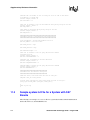
Sample system.txt File for a System with SS7 Boards . . . . . . . . . . . . . . . . . . . . . . . . . .
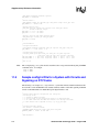
Sample config.txt File for a System with Circuits and Signalling on an SS7 Board . . . . .
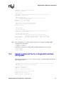
Sample config.txt File for a System with Circuits and Signaling on DTI Trunks . . . . . . .
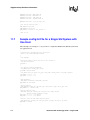
Sample system.txt File for a Single-SIU and Dual-SIU System. . . . . . . . . . . . . . . . . . . .
Sample config.txt File for a Single SIU System with One Host . . . . . . . . . . . . . . . . . . . .
Sample config.txt File for a Single-SIU System with Two Host . . . . . . . . . . . . . . . . . . . .
Sample config.txt File for SIU A in a Dual-Resilient SIU System with a Single Host . . . .
Sample config.txt File for SIU B in a Dual-Resilient SIU System with a Single Host . . . .
121
122
124
125
126
127
128
129
130
131
Glossary . . . . . . . . . . . . . . . . . . . . . . . . . . . . . . . . . . . . . . . . . . . . . . . . . . . . . . . . . . . . . . . . . . 133
Index . . . . . . . . . . . . . . . . . . . . . . . . . . . . . . . . . . . . . . . . . . . . . . . . . . . . . . . . . . . . . . . . . . . . . 137
Global Call SS7 Technology Guide – August 2005
5
Contents
Figures
1
2
3
4
5
6
7
8
9
10
6
Signaling and Information Transfer Networks . . . . . . . . . . . . . . . . . . . . . . . . . . . . . . . . . . . . . . 16
SS7 Protocol Stack Layers. . . . . . . . . . . . . . . . . . . . . . . . . . . . . . . . . . . . . . . . . . . . . . . . . . . . . 17
Intel NetStructure SS7 Board Configuration 1 . . . . . . . . . . . . . . . . . . . . . . . . . . . . . . . . . . . . . . 23
Intel NetStructure SS7 Board Configuration 2 . . . . . . . . . . . . . . . . . . . . . . . . . . . . . . . . . . . . . . 24
Intel NetStructure SS7 Board Configuration 3 . . . . . . . . . . . . . . . . . . . . . . . . . . . . . . . . . . . . . . 24
SIU Configuration 1 . . . . . . . . . . . . . . . . . . . . . . . . . . . . . . . . . . . . . . . . . . . . . . . . . . . . . . . . . . 26
SIU Configuration 2 . . . . . . . . . . . . . . . . . . . . . . . . . . . . . . . . . . . . . . . . . . . . . . . . . . . . . . . . . . 27
SIU Configuration 3 . . . . . . . . . . . . . . . . . . . . . . . . . . . . . . . . . . . . . . . . . . . . . . . . . . . . . . . . . . 28
Global Call Architecture . . . . . . . . . . . . . . . . . . . . . . . . . . . . . . . . . . . . . . . . . . . . . . . . . . . . . . . 29
Global Call SS7 Architecture . . . . . . . . . . . . . . . . . . . . . . . . . . . . . . . . . . . . . . . . . . . . . . . . . . . 30
Global Call SS7 Technology Guide – August 2005
Contents
Tables
1
2
3
4
5
6
7
8
9
10
11
12
13
14
15
16
17
18
19
20
21
22
23
24
25
26
27
28
29
30
31
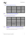
Intel NetStructure SS7 Board Configurations - Features and Benefits . . . . . . . . . . . . . . . . . . .
Capacity of SIUs . . . . . . . . . . . . . . . . . . . . . . . . . . . . . . . . . . . . . . . . . . . . . . . . . . . . . . . . . . . .
SIU Configurations - Features and Benefits . . . . . . . . . . . . . . . . . . . . . . . . . . . . . . . . . . . . . . .
SCbus Clock Configuration for PCCS6 Boards . . . . . . . . . . . . . . . . . . . . . . . . . . . . . . . . . . . . .
CT Bus Clock Configuration for Intel NetStructure SS7 CompactPCI and PCI Boards. . . . . . .
Error Codes for SS7 Server Start Failure . . . . . . . . . . . . . . . . . . . . . . . . . . . . . . . . . . . . . . . . .
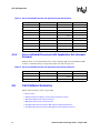
Opening a Device Scenario . . . . . . . . . . . . . . . . . . . . . . . . . . . . . . . . . . . . . . . . . . . . . . . . . . . .
Common Outbound Call Scenario . . . . . . . . . . . . . . . . . . . . . . . . . . . . . . . . . . . . . . . . . . . . . . .
Alternative Outbound Call Scenario for ITU-T Operation Only . . . . . . . . . . . . . . . . . . . . . . . . .
Outbound Call Scenario Where ACM has No Indication . . . . . . . . . . . . . . . . . . . . . . . . . . . . . .
Common Inbound Call Scenario . . . . . . . . . . . . . . . . . . . . . . . . . . . . . . . . . . . . . . . . . . . . . . . .
Alternative Inbound Call Scenario . . . . . . . . . . . . . . . . . . . . . . . . . . . . . . . . . . . . . . . . . . . . . . .
Application-Initiated Disconnect Scenario . . . . . . . . . . . . . . . . . . . . . . . . . . . . . . . . . . . . . . . . .
Network-Initiated Disconnect Scenario . . . . . . . . . . . . . . . . . . . . . . . . . . . . . . . . . . . . . . . . . . .
Server-Initiated Disconnect with Application Informed Scenario . . . . . . . . . . . . . . . . . . . . . . . .
Server-Initiated Disconnect with Application Not Informed Scenario. . . . . . . . . . . . . . . . . . . . .
Glare Scenario. . . . . . . . . . . . . . . . . . . . . . . . . . . . . . . . . . . . . . . . . . . . . . . . . . . . . . . . . . . . . .
Inbound Call Before Completion of Call Clearing Scenario . . . . . . . . . . . . . . . . . . . . . . . . . . . .
Disconnect Collision on SRL Queue . . . . . . . . . . . . . . . . . . . . . . . . . . . . . . . . . . . . . . . . . . . . .
Disconnect Collision on MQ Queue. . . . . . . . . . . . . . . . . . . . . . . . . . . . . . . . . . . . . . . . . . . . . .
Disconnect Collision on GCT Queue with Application Informed . . . . . . . . . . . . . . . . . . . . . . . .
Disconnect Collision on GCT Queue with Application Not Informed . . . . . . . . . . . . . . . . . . . . .
Successful Outbound Out-Of-Call Continuity Test Scenario . . . . . . . . . . . . . . . . . . . . . . . . . . .
Successful Inbound Out-Of-Call Continuity Test Scenario . . . . . . . . . . . . . . . . . . . . . . . . . . . .
Outbound Out-Of-Call Continuity Test One Failure Scenario . . . . . . . . . . . . . . . . . . . . . . . . . .
Inbound Out-Of-Call Continuity Test with One Failure Scenario . . . . . . . . . . . . . . . . . . . . . . . .
Successful Outbound In-Call Continuity Test Scenario . . . . . . . . . . . . . . . . . . . . . . . . . . . . . . .
Successful Inbound In-Call Continuity Test Scenario . . . . . . . . . . . . . . . . . . . . . . . . . . . . . . . .
Outbound In-Call Continuity Test with One Failure Scenario (Old Method) . . . . . . . . . . . . . . .
Outbound In-Call Continuity Test with One Failure Scenario (New Method). . . . . . . . . . . . . . .
Inbound In-Call Continuity Test with One Failure Scenario . . . . . . . . . . . . . . . . . . . . . . . . . . . .
Global Call SS7 Technology Guide – August 2005
23
25
26
35
36
50
53
54
54
55
55
56
57
57
58
58
59
59
60
60
61
61
62
63
64
64
65
66
67
68
69
7
Contents
8
Global Call SS7 Technology Guide – August 2005
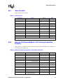
Revision History
This revision history summarizes the changes made in each published version of this document.
Document No.
Publication Date
Description of Revisions
05-2274-004
July 2005
General: Updates to acknowledge Intel NetStructure® as a registered trademark.
General: Replaced the term “DCM” with “Intel® Dialogic® configuration manager”.
General: Updates to indicate support for SS7G21 and SS7G22 Signaling Gateways
in SIU Mode.
Configuring an Intel NetStructure SS7 Board as a TDM Bus Master: Added text to
describe configuration in Linux systems.
ISUP Configuration: Added para to indicate support for CAL_MSG_HEARTBEAT
ISUP messages.
Dual-Resilient SIU Configuration Parameters: Added the SIU.Dual.TolerateCallTime
parameter and description.
Global Call Functions Supported by SS7: Added new supported utility functions:
gc_util_copy_parm_blk( ), gc_util_find_parm_ex( ),
gc_util_insert_parm_ref_ex( ) and gc_util_next_parm_ex( ) and new
unsupported functions: gc_AcceptModifyCall( ), gc_SetAuthenticationInfo( ),
gc_RejectModifyCall( ) and gc_ReqModifyCall( ).
gc_GetSigInfo( ) Variances for SS7: Rephrased note.
gc_MakeCall( ) Variances for SS7: Rephrased the statement of support for the
timeout parameter.
05-2274-003
March 2005
General: Updates to indicate support for SS7HD boards (both PCI and CompactPCI).
General: Changed board names as follows (excluding command names and book
titles):
- SPCI2S to SS7SPCI2S
- SPCI4 to SS7SPCI4
- CPM8 to SS7CPM8
05-2274-002
September 2004
SS7 Server Log File: Updated the location of the SS7 server log file under Windows.
gc_GetParm( ) Variances for SS7 : Added new GCPR_IGNORE_BCI parameter.
gc_SetParm( ) Variances for SS7 : Added new GCPR_IGNORE_BCI parameter.
Global Call SS7 Software Configuration (gcss7.cfg): Added the following
configuration parameters: Service.IgnoreBCI, Service.CleanCidBit15,
SIU.ConfigureRsiLinks.
Sample system.txt File for a System with SS7 Boards: Updated.
Sample config.txt File for a System with Circuits and Signalling on an SS7 Board:
Updated.
Sample config.txt File for a System with Circuits and Signaling on DTI Trunks:
Updated.
Sample system.txt File for a Single-SIU and Dual-SIU System: Updated.
Sample config.txt File for a Single SIU System with One Host: Updated.
Sample config.txt File for a Single-SIU System with Two Host: Updated.
Global Call SS7 Technology Guide — August 2005
9
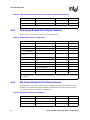
Revision History
Document No.
Publication Date
Description of Revisions
05-2274-002
September 2004
Sample config.txt File for SIU A in a Dual-Resilient SIU System with a Single Host:
Updated.
(continued)
Sample config.txt File for SIU B in a Dual-Resilient SIU System with a Single Host:
Updated.
Section 3.5, “Configuring an Intel NetStructure SS7 Board as a TDM Bus Master”, on
page 44: New section added.
Section 5.6, “Using Overlap Send and Receive”, on page 75: Updated to indicate:
1) limitations when using gc_SendMoreInfo( ), 2) gc_SndMsg( ) can still be
used to send SAM.
05-2274-002-01
March 2004
Table 1, “Intel NetStructure SS7 Board Configurations - Features and Benefits”, on
page 23: Removed reference to ISA in the caption and updated the first row to
indicate support for “four” signaling links, not “three”.
Section 3.8.1.2, “SIU Systems”, on page 49: Updated the first code segment under
step 3 to reference RSICMD.EXE.
Table 6, “Error Codes for SS7 Server Start Failure”, on page 50: Updated the error
code descriptions for 0x5001 and 0x5002.
Section 3.8.2.4, “SIU does not Function Correctly After Modification of config.txt”, on
page 51: Updated the text for step 2 to better explain that 0x0d is equivalent to a
carriage return symbol.
Section 10.1, “SS7-Specific Error Codes”, on page 115: Updated some descriptions
and added asterisks to identify codes not currently supported.
Section 10.2, “SS7-Specific Event Cause Codes”, on page 118: Added new section.
Section 11.8, “Sample config.txt File for a Single-SIU System with Two Host”, on
page 129: Added new section.
Section 11.6, “Sample system.txt File for a Single-SIU and Dual-SIU System”, on
page 127: Added mandatory LOCAL and FORK_PROCESS commands.
Section 11.9, “Sample system.txt File for a Dual-Resilient SIU System”, on page 127:
Added mandatory LOCAL and FORK_PROCESS commands.
Section 11.9, “Sample config.txt File for SIU A in a Dual-Resilient SIU System with a
Single Host”, on page 130: Updated MTP_ROUTE commands.
Section 11.10, “Sample config.txt File for SIU B in a Dual-Resilient SIU System with a
Single Host”, on page 131: Updated MTP_ROUTE commands.
10
Global Call SS7 Technology Guide — August 2005
Revision History
Document No.
Publication Date
Description of Revisions
05-2274-001
November 2003
Initial version of document. Much of the information contained in this document was
previously published in the Global Call SS7 Technology User’s Guide for Windows
Operating Systems, document number 05-1380-006 and the Global Call SS7
Technology User’s Guide for Linux Operating Systems, document number 05-1936001. Major changes since these document versions are listed below.
General: Updates to accommodate all Global Call SS7 software configuration in a
single file called gcss7.cfg.
Integrated the “Troubleshooting” chapter into the “Configuration and Startup”
chapter.
Viewing Parameter Values With the Intel Dialogic Configuration Manager: Added
section to explain that it is only possible to view key parameters values in the
configuration manager (DCM). Configuration of parameters previously
configured using DCM is now done using the gcss7.cfg file.
SS7 Call Scenarios: Replaced existing scenarios with more up-to-date and
comprehensive scenarios.
Building Global Call SS7 Applications: Added as a new chapter.
gc_OpenEx( ) Variances for SS7: Removed “:L_SS7” from the devicename string; no
longer required. (PT 30317) :
S7_SIGINFO_BLK: Updated the length parameter description; 1 must be added for
the NULL character.
Supplementary Reference Information: Updated the sample configuration files.
Global Call SS7 Technology Guide — August 2005
11
Revision History
12
Global Call SS7 Technology Guide — August 2005
About This Publication
The following topics provide information about this publication.
• Purpose
• Intended Audience
• How to Use This Publication
• Related Information
Purpose
This guide is for users of the Global Call API writing applications that use SS7 technology. This
guide provides Global Call SS7-specific information only and should be used in conjunction with
the Global Call API Programming Guide and the Global Call API Library Reference that describe
the generic behavior of the Global Call API.
Intended Audience
This guide is intended for:
• Distributors
• System Integrators
• Toolkit Developers
• Independent Software Vendors (ISVs)
• Value Added Resellers (VARs)
• Original Equipment Manufacturers (OEMs)
This publication assumes that the audience is familiar with the Windows* and Linux* operating
systems and has experience using the C programming language.
How to Use This Publication
Refer to this guide after you have installed the system software that includes the Global Call
software.
This guide is divided into the following chapters:
• Chapter 1, “SS7 Overview” gives a brief introduction to SS7 technology for novice users.
• Chapter 2, “Global Call Architecture for SS7” describes how Global Call can be used with
SS7 technology and provides an overview of the architecture.
Global Call SS7 Technology Guide — August 2005
13
About This Publication
• Chapter 4, “SS7 Call Scenarios” provides some call scenarios that are specific to SS7
technology.
• Chapter 3, “Configuration and Startup” describes how to configure the SS7 software
environment and how to start a system that contains SS7 boards.
• Chapter 5, “SS7-Specific Operations” describes how to use the Global Call API to perform
SS7-specific operations, such using overlap send and receive, performing continuity checks,
etc.
• Chapter 6, “Building Global Call SS7 Applications” provides guidelines for building Global
Call applications that use SS7 technology.
• Chapter 7, “Debugging Global Call SS7 Applications” provides information for debugging
Global Call applications that use SS7 technology.
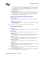
• Chapter 8, “SS7-Specific Function Information” describes the additional functionality of
specific Global Call functions used with SS7 technology.
• Chapter 9, “SS7-Specific Data Structures” provides a data structure reference for SS7-specific
data structures.
• Chapter 10, “SS7-Specific Error Codes and Event Cause Codes” provides descriptions of SS7-
specific event cause codes.
• Chapter 11, “Supplementary Reference Information” provides supplementary information
including technology references and sample configuration files.
• A Glossary and an Index can be found at the end of the document.
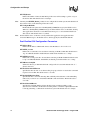
Related Information
Refer to the following documents and web sites when developing Global Call applications that use
SS7 technology:
• System7 ISUP Programmer’s Manual
• System7 TUP Programmer’s Manual
• System7 Software Environment Programmer’s Manual
• Global Call API Library Reference
• Global Call API Programming Guide
• http://developer.intel.com/design/telecom/support/ (for technical support)
• http://www.intel.com/network/csp/ (for product information)
Note:
14
The SS7 stack and system documentation is available for download at
http://resource.intel.com/telecom/support/ss7/downloads/index.htm. You will need to register with
the support site to gain access to the documentation.
Global Call SS7 Technology Guide — August 2005
SS7 Overview
1.
1
This chapter provides a brief overview of Signaling System 7 (SS7) technology. It is a high-level
description of the technology and does not intend to provide details of any aspect of SS7
technology. Some references to where more detailed information can be obtained are provided.
Topics covered by this chapter include:
• SS7 and Computer Telephony . . . . . . . . . . . . . . . . . . . . . . . . . . . . . . . . . . . . . . . . . . . . 15
• SS7 Protocol Stack . . . . . . . . . . . . . . . . . . . . . . . . . . . . . . . . . . . . . . . . . . . . . . . . . . . . 17
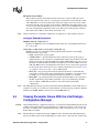
1.1
SS7 and Computer Telephony
Signaling System 7 (SS7) is a common-channel signaling (CCS) system that defines the procedures
and protocol by which network elements (signaling points) in the public switched telephone
network (PSTN) exchange information over a digital signaling network to facilitate wireline and
wireless (cellular) call setup, routing and control.
In an SS7 network, control messages (packets) are routed through the network to perform call
management (setup, maintenance, and termination) and network management functions. Therefore,
the common-channeling signaling SS7 network is a packet-switched network, even though the
network being controlled can be a circuit-switched network (PSTN).
An SS7 network is comprised of network elements connected together using signaling links. Such
a network element that is capable of handling SS7 control messages is called a Signaling Point
(SP). All signaling points in a SS7 network are identified by a unique code known as a point code.
There are three different basic types of network elements:
• Signaling Transfer Point (STP) - A signaling point that is capable of routing control
messages; that is, a message received on one signaling link is transferred to another link.
• Service Control Point (SCP) - Contains centralized network databases for providing
enhanced services. An SCP accepts queries from an SP and returns the requested information
to the originator of the query. For example, when an 800 call is initiated by a user, the
originating SP sends a query to an 800 database (at the SCP) requesting information on how to
route the call. The SCP returns the routing information to the SP originating the query and the
call proceeds.
• Service Switching Point (SSP) - A signaling point in a switching office, either a local
exchange or a tandem office. An SSP has the capability to control voice circuits via a voice
switch. The SSP can either integrate the voice switch or can be an adjunct computer to the
voice switch.
Network elements are interconnected using signaling links. A signaling link is a bidirectional
transmission path for signaling, comprised of two data channels operating together in opposite
directions at the same data rate. The standard rate on a digital transmission channel is 56 or 64
Global Call SS7 Technology Guide — August 2005
15
SS7 Overview
kilobits per second (kbps), although the minimum signaling rate for call control applications is 4.8
kbps. Network management applications may use bit rates lower than 4.8 kbps.
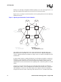
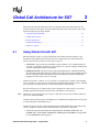
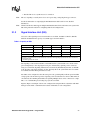
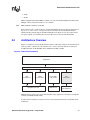
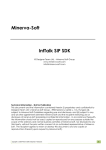
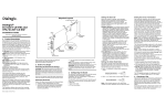
Figure 1 shows an example of an SS7 network that carries signaling information for the underlying
PSTN network nodes.
Figure 1. Signaling and Information Transfer Networks
SCP
SCP
STP
STP
SP
User
LE
SP
User
LE
STP
STP
SP
SP
LE
LE
SP
TC
PSTN Nodes:
LE - Local Exchange
TC - Transfer Center
SP
LE
SP
TC
SS7 Nodes:
SP - Signaling Point
STP - Signaling Transfer Point
The signaling network is independent of the circuit-switched network. Signaling links can be
physically located on trunks that carry voice circuits, but can also be completely independent, or
even use a different transmission medium (for example, serial V.35). SSPs are the bridges between
both networks.
To ensure reliable transfer of signaling information in an environment susceptible to transmission
disturbances or network failures, an SS7 network employs error detection and error correction on
each signaling link. An SS7 network is normally designed with redundant signaling links and
includes functions for the automatic diversion of signaling traffic to alternative paths in case of link
failures.
Another type of network element that appears in an Intelligent Network (IN) is the Intelligent
Peripheral (IP). An IN is a service-independent telecommunications network, that is, a network in
which intelligence is taken out of the switch and placed in computer nodes that are distributed
throughout the network. An IP is an SP that provides enhanced services to the SSP, usually under
16
Global Call SS7 Technology Guide — August 2005
SS7 Overview
control of an SCP. Those services range from providing user-input prompts and collecting digits to
providing a complete service application.
1.2
SS7 Protocol Stack
The hardware and software functions of the SS7 protocol are divided into functional abstractions
called levels. These levels map loosely to the Open Systems Interconnect (OSI) 7-layer reference
model defined by the International Standards Organization (ISO). This model describes the
structure for modeling the interconnection and exchange of information between users in a
communications system.
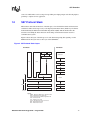
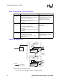
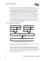
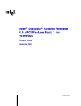
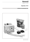
Figure 2 shows the layers of the SS7 protocol stack when transporting SS7 signaling over the
PSTN and how the layers relate to the layers of the OSI Model.
Figure 2. SS7 Protocol Stack Layers
SS7 Model
OSI Model
OMAP
ASEs
Application
TCAP
TUP
Presentation
ISUP
Session
Transport
SCCP
Network
MTP3
NSP
MTP
MTP2
Data Link
MTP1
Physical
Legend:
OMAP - Operations Maintenance Application Part
ASEs - Application Service Elements
TCAP - Transaction Capabilities Application Part
ISUP - ISDN User Part
TUP - Telephony User Part
SCCP - Signaling Connection Control Part
MTP - Message Transfer Part
NSP - Network Service Part
Global Call SS7 Technology Guide — August 2005
17
SS7 Overview
1.2.1
Lower Stack Layers for SS7 Over a Circuit-Switched
Network
When transporting SS7 signaling over a circuit-switched network, the lowest three levels of the
SS7 stack, called the Message Transfer Part (MTP), provide a reliable but connectionless
(datagram or packet style) service for routing messages through the SS7 network. This service is
used by the various user parts described in Section 1.2.2, “Upper Stack Layers”, on page 18.
The MTP is subdivided into three parts as follows:
• MTP1, also called the signaling data link layer, is concerned with the physical and electrical
characteristics of the signaling links. MTP1 corresponds to the physical layer of the OSI
model.
• MTP2, also called the signaling link layer, is a data link control protocol that provides for the
reliable sequenced delivery of data across a signaling data link. MTP2 corresponds to the data
link layer of the OSI model.
• MTP3, also called the signaling network layer, provides for routing data across multiple
STPs from control source to control destination. MTP3 corresponds to a part of the network
layer of the OSI model.
The connectionless nature of the MTP provides a low-overhead facility tailored to the requirements
of telephony. However, the MTP does not provide all the services of the corresponding OSI
Network layer. To support Integrated Services Digital Network (ISDN) applications such as
network management that requires expanded addressing capability and reliable message transfer, a
separate module is provided:
• Signaling Connection Control Part (SCCP), defines a wide variety of network-layer
services. SCCP corresponds to part of the network layer of the OSI model.
The MTP and the SCCP together form the Network Service Part (NSP). The resulting split in OSI
network functions between MTP and SCCP has the advantage that the higher-overhead SCCP
services can be used only when required, and the more efficient MTP services can be used in other
applications.
1.2.2
Upper Stack Layers
The upper parts of the SS7 protocol stack are concerned with the actual contents of the SS7
messages and are sometimes called application layers. These include:
• ISDN User Part (ISUP), provides the signaling needed for basic ISDN circuit-mode bearer
services as well as ISDN supplementary services having end-to-end significance. ISUP is the
protocol that supports ISDN in the Public Switched Telephone Network. It corresponds to the
transport, session, presentation, application layers and part of the network layer of the OSI
model.
• Telephony User Part (TUP), an ISUP predecessor in providing telephony signaling functions.
TUP has now been made obsolete by ISUP in most countries and in the international network.
The TUP corresponds to the transport, session, presentation, application layers and part of the
network layer of the OSI model.
18
Global Call SS7 Technology Guide — August 2005
SS7 Overview
• Transaction Capabilities Application Part (TCAP), provides the mechanisms for
transaction-oriented (rather than connection-oriented) applications and functions. The TCAP
corresponds to the application layer in the OSI model. TCAP is often used for database access
by the SS7 switches but has many other applications through the network.
• Operations and Maintenance Application Part (OMAP), specifies network management
functions and messages related to operations and maintenance. The OMAP corresponds to the
application layer in the OSI model.
• Application Service Elements (ASEs), represent user parts that are highly application-
specific, for example:
– Intelligent Network Application Part (INAP)
– Mobile Application Part (MAP), provides the signaling functions necessary for the
mobile capabilities of voice and non-voice applications in a mobile network
– IS41, an ANSI signaling standard used in cellular networks
For any application, all three MTP layers and at least one application layer are required. Typically,
the word “user” in modules such as ISUP, TUP and so on explicitly identifies the module as a user
of the transport mechanism MTP.
SS7 computer telephony applications that transport SS7 signaling over a circuit-switched network
can use the ISUP (on top of the MTP layers) to control voice circuits, and sometimes TCAP to
query for information or to receive commands from a SCP.
Global Call SS7 Technology Guide — August 2005
19
SS7 Overview
20
Global Call SS7 Technology Guide — August 2005
Global Call Architecture for SS7
2.
2
This chapter describes the Global Call software architecture when using SS7 technology and
provides a high-level description of how the Global Call API can be used to develop call control
applications that use SS7. Topics include:
• Using Global Call with SS7. . . . . . . . . . . . . . . . . . . . . . . . . . . . . . . . . . . . . . . . . . . . . . 21
• Architecture Overview. . . . . . . . . . . . . . . . . . . . . . . . . . . . . . . . . . . . . . . . . . . . . . . . . . 29
• Dialogic SS7 Server. . . . . . . . . . . . . . . . . . . . . . . . . . . . . . . . . . . . . . . . . . . . . . . . . . . . 31
• Global Call SS7 Library . . . . . . . . . . . . . . . . . . . . . . . . . . . . . . . . . . . . . . . . . . . . . . . . 31
• SS7 Protocol Stack . . . . . . . . . . . . . . . . . . . . . . . . . . . . . . . . . . . . . . . . . . . . . . . . . . . . 32
2.1
Using Global Call with SS7
The SS7 signaling system is a packet-switched data network that forms the backbone of the
international telecommunications network. SS7 plays an important role in both wireline and
wireless networks. SS7 provides two basic types of services:
• Call Control - SS7 provides fast and reliable common channel or out-of-band signaling for
call control. At the heart of the SS7 call control function is a network of highly-reliable packet
switches called Signal Transfer Points (STPs).
• Intelligent Network - The SS7 network enables the implementation of Intelligent Network
(IN) and Advanced Intelligent Network (AIN) services. SS7 messages traverse STPs and enlist
the use of System Control Points (SCPs), Service Switching Points (SSPs) and Intelligent
Peripherals to deliver these services to the user.
Global Call provides a common call control interface for applications, regardless of the signaling
protocol needed to connect to the local telephone network. This manual describes the use of Global
Call to perform call control functions in a network that supports SS7 signaling.
For SS7 and other protocols, Global Call provides a higher level of abstraction for call control,
shielding application developers from the need to deal with the low-level details.
Note:
Global Call covers only the call control aspects of SS7. It does not provide an API for other user
parts such as TCAP and INAP.
Currently, Global Call SS7 supports the ISUP protocol (ANSI version T1.609, ITU versions Q.761
to Q.764 and Q.767) and the TUP protocol.
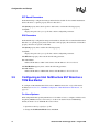
Global Call supports the SS7 solutions implemented using Intel NetStructure SS7 hardware and
software. Solutions are based on the following hardware and software components:
• SS7 Interface Boards: Intel NetStructure® PCCS6 (ISA), SS7SPCI4, SS7SPCI2S, and
SS7HDP (PCI), and SS7CPM8, SS7HDCD16, SS7HDCQ16 and SS7HDCS8 (CompactPCI)
boards. SS7HDCN16 is not supported.
Global Call SS7 Technology Guide — August 2005
21
Global Call Architecture for SS7
• Signaling Interface Units: Intel NetStructure® SIU131, SIU231, SIU520 and SS7G2x
(operating in SIU mode)
• Intel NetStructure® SS7 Protocols
Note:
2.1.1
The PCCS6 (ISA) boards are licensed to handle either 64 or 256 circuits. The SS7SPCI4 and
SS7SPCI2S (PCI) and SS7CPM8 (CompactPCI) boards can be licensed for 1024 or 4096 circuits.
SS7HDP (PCI), and SS7HDCS8, SS7HDCD16 and SS7HDCQ16 (CompactPCI) boards can be
licensed for 8192 or 32768 circuits. The SIUs can be licensed to handle up to 4,096 circuits for
SIU131, up to 16,384 circuits for SIU231, SIU520 and SS7G21 and up to 65,535 circuits for
SS7G22. Contact Intel for information about licensing.
SS7 Interface Boards
Intel NetStructure SS7 boards are intelligent SS7 signaling boards for use in PC-compatible
computers. Intel NetStructure SS7 boards combine on-board support for the SS7 common channel
signaling protocols, one, two, four or eight interfaces depending on the board type, and CT Bus
local PCM time slots on a mezzanine bus. A dedicated on-board processor ensures that
performance is independent of the load on the host PC. Downloadable operating software makes
the board easy to upgrade when protocol specification changes are necessary.
The PCCS6 board is an ISA SS7 board with one or two E1 or T1 line interfaces, and because SS7
signaling is carried separately from the PCM stream in some situations, a V.35-compatible serial
interface is also provided. The SCbus connection allows system integration with the complete set
of Intel® Dialogic® solutions and a wide range of third-party voice, data, and fax products. A
digital cross-connect switch allows voice and signaling channels to be connected between the line
interfaces, the SCbus time slots, and the protocol processor.
The SS7SPCI4 and SS7SPCI2S boards are PCI boards that feature four T1/E1 or two T1/E1
interfaces, an H.100 PCM Highway, two serial network interfaces and four SS7 links.
The SS7HDP is an SS7 PCI board that provides up to four E1/T1 interfaces, V.11 (V.35compatible) serial ports, an H.110 PCM Highway, and 64 SS7 links.
The SS7CPM8 is an SS7 CompactPCI board that provides up to eight E1/T1 interfaces, V.11 (V.35compatible) serial ports, an H.110 PCM Highway, and four SS7 links.
The SS7HDCS8 is an SS7 CompactPCI board that provides up to eight E1/T1 interfaces, V.11
(V.35-compatible) serial ports, an H.110 PCM Highway and 32 SS7 links.
The SS7HDCD16 is an SS7 CompactPCI board that provides up to sixteen E1/T1 interfaces, V.11
(V.35-compatible) serial ports, an H.110 PCM Highway and 64 SS7 links.
The SS7HDCQ16 is an SS7 CompactPCI board that provides up to sixteen E1/T1 interfaces, V.11
(V.35-compatible) serial ports, an H.110 PCM Highway and 128 SS7 links.
Note:
Currently only one Intel NetStructure SS7 board can be used in a system.
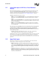
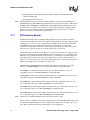
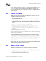
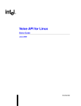
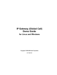
Figure 3, Figure 4, and Figure 5 show some configurations that use an Intel NetStructure SS7 board
in conjunction with Intel Dialogic boards in a single chassis that in each case supports up to 256
ports. Table 1 summarizes the features and benefits of each configuration.
22
Global Call SS7 Technology Guide — August 2005
Global Call Architecture for SS7
Table 1. Intel NetStructure SS7 Board Configurations - Features and Benefits
Configuration
Intel NetStructure
SS7 Board
Configuration 1
Features
Benefits
T1/E1 line with SS7 signaling connected to the Intel
NetStructure SS7 board
Multiple signaling reliability
with up to four signaling links
Voice channels routed through the Intel NetStructure
SS7 board via the SCbus
SS7 T1/E1 managed by the Intel NetStructure SS7
board
Intel NetStructure
SS7 Board
Configuration 2
SS7 link and bearer channels enter through Intel
Dialogic network interface board
SCbus bus clocking managed
via Intel Dialogic boards
T1/E1 with SS7 Signaling channel connects to a
voice board
All voice and data resources
managed by Intel Dialogic
boards
The SS7 signaling is routed to the Intel NetStructure
SS7 board via the SCbus
Intel NetStructure
SS7 Board
Configuration 3
The SS7 link is connected via a synchronous V.35
connection
All T1/E1 trunks (bearing voice circuits) enter through
Intel Dialogic network interface boards
Separates the signaling
channel from the bandwidth
channels
All signaling controlled using
V.35 clocking via two V.11
connections on the Intel
NetStructure SS7 board
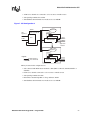
Figure 3. Intel NetStructure SS7 Board Configuration 1
PC
Application
DM/V960-4T1
CT Bus
DM/V960-4T1
E1/T1
Intel® NetStructure™
SS7 PCI or CompactPCI
Board
SS7
T1 *
T1 *
DM/V2400A
Legend:
SS7 Signaling
Voice Channels
Note: * indicates that for E1 interfaces, the equivalent
boards with E1 interfaces must be used.
The key features in this configuration are:
• The T1/E1 line with the SS7 signaling is connected to the Intel NetStructure SS7 board
• B-channels are routed through the Intel NetStructure SS7 board to voice resource via SCbus
• The SS7 T1/E1 is managed by the Intel NetStructure SS7 board
• Other T1/E1 trunks are managed by Intel Dialogic network interface boards
Global Call SS7 Technology Guide — August 2005
23
Global Call Architecture for SS7
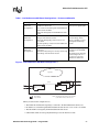
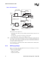
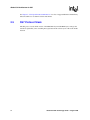
Figure 4. Intel NetStructure SS7 Board Configuration 2
PC
Application
DM/V960-4T1
CT Bus
DM/V960-4T1
T1 *
SS7
T1 *
DM/V960-4T1
Intel® NetStructure™
SS7 PCI or CompactPCI
Board
T1 *
Legend:
SS7 Signaling
Voice Channels
Note: * indicates that for E1 interfaces, the equivalent
boards with E1 interfaces must be used.
The key features in this configuration are:
• SS7 link and bearer channels enter through Intel Dialogic network interface board
• All voice and data resources managed by Intel Dialogic boards
• T1/E1 with SS7 signaling connects to a voice board
• The SS7 signaling is routed to the Intel NetStructure SS7 board via the SCbus
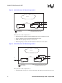
Figure 5. Intel NetStructure SS7 Board Configuration 3
PC
Application
DM/V960-4T1
CT Bus
DM/V960-4T1
SS7
V.35 Link
Intel® NetStructure™
SS7 PCI or CompactPCI
Board
T1 *
T1 *
DM/V2400A
Legend:
SS7 Signaling
Voice Channels
Note: * indicates that for E1 interfaces, the equivalent
boards with E1 interfaces must be used.
The key features in this configuration are:
• All T1/E1 trunks (bearing voice circuits) enter through Intel Dialogic network interface boards
24
Global Call SS7 Technology Guide — August 2005
Global Call Architecture for SS7
• The SS7 link is via a synchronous V.35 connection
Note:
The V.35 signaling is actually done via two V.11 ports using a using 26-pin D-type connector.
See the documentation accompanying the Intel NetStructure SS7 board for more detailed
information.
Note:
2.1.2
Global Call SS7 does not support multiple Intel NetStructure SS7 boards in the same system. The
SIU is the preferred solution for configuring multi-board configurations.
Signal Interface Unit (SIU)
A black-box SS7 signaling server. Several models are available, the SIU131, SIU231, SIU520,
SS7G21 and SS7G22. The capacity of each SIU type is shown in Table 2.
Table 2. Capacity of SIUs
SIU131
SIU231
SIU520
SS7G21
SS7G22
Signalling cards
2
12
3
3
3**
Links
6
32
12
12
128 (max)
Linksets
6
8
12
12
64
Call Rate
100/sec.*
100/sec.*
450/sec.*
???
???
* Call rates can depend on issues in the network such as the way in which signaling is presented. The values should not be
considered absolute.
** SS7HDP hig-density SS7 boards
SS7 signaling is extracted from the E1 or T1 trunks into the system and the voice circuits can be
passed transparently to the outgoing E1 or T1 ports. Alternatively, signaling can be connected
using V.35 serial links. Signaling information is automatically distributed by the SIU, via TCP/IP,
to the host that controls the telephony circuits. Typically this is the system where the voice trunks
are terminated on Intel Dialogic interface boards.
Two SIUs can be configured to share the same point code, providing fully resilient operation within
a single point code. In normal operation, signaling can be load-shared across the two SIUs. Then, if
one unit fails, the remaining unit handles all signaling. Multiple hosts can be connected to a single
SIU, or to a resilient SIU pair, allowing large systems to be built.
Figure 6, Figure 7 and Figure 8 show some configurations using the SIU in conjunction with Intel
Dialogic boards. Table 3 summarizes the features and benefits of each configuration.
Global Call SS7 Technology Guide — August 2005
25
Global Call Architecture for SS7
Table 3. SIU Configurations - Features and Benefits
Configuration
SIU
Configuration 1
Features
Benefits
V.35 SS7 connection to SIU (SIU131, SIU231,
SIU520 or SS7G21)
Manage greater number of channels
than a single card
Additional T1/E1 B channels are connected to
voice resources on media servers
Reduced maintenance cost due to
smaller overhead relative to
management of more circuits
SS7 signaling terminated on an SIU
SIU distributes SS7 information to media servers
over TCP/IP
SIU
Configuration 2
SS7 E1/T1 connected to SIU (SIU131, SIU231,
SIU520, SS7G21 or SS7G22)
SS7 signaling terminated on SIU
Additional T1/E1 B channels
available for voice resources on
media servers
Voice channels routed through SIU via “drop and
insert” E1/T1
SIU distributes SS7 information to media servers
over TCP/IP
SIU
Configuration 3
SS7 link interconnects SIUs to provide a reliable
management channel
Provides dual point code
management
Dual SS7 links to separate SIUs
Redundant SS7 links for back-up of
signaling connections
SS7 distributed through a single or separate
TCP/IP connection
Figure 6. SIU Configuration 1
TCP/IP
SS7 over TCP/IP
SS7 V.35 Link
Application
CT Bus
SIU
DM/V960-4T1
DM/V1200-4E1
E1/T1
E1/T1
E1/T1
(Bearer
Only)
Application
Platform
Application
CT Bus
E1/T1
E1/T1
E1/T1
Legend:
SS7 Signaling
Voice Channels
DM/V960-4T1
DM/V1200-4E1
(Bearer
Only)
The key features in this configuration are:
• V.35 SS7 connection to SIU (SIU131, SIU231, SIU520 or SS7G21)
26
Global Call SS7 Technology Guide — August 2005
Global Call Architecture for SS7
• T1/E1 voice channels are connected to voice resources on media servers
• SS7 signaling terminated on an SIU
• SIU distributes SS7 information to media servers over TCP/IP
Figure 7. SIU Configuration 2
TCP/IP
SS7
Signaling
T1/E1
SS7 over TCP/IP
SIU
Application
CT Bus
E1/T1
E1/T1
E1/T1
DM/V960-4T1
DM/V1200-4E1
T1/E1
Application
Platform
Application
CT Bus
Legend:
SS7 Signaling
Voice Channels
DM/V960-4T1
DM/V1200-4E1
E-1/T-1
E-1/T-1
E-1/T-1
The key features in this configuration are:
• SS7 connected with E1/T1 bearer channels to SIU (SIU131, SIU231, SIU520, SS7G21 or
SS7G22)
• E1/T1 voice channels connected to voice resources on media servers
• SS7 signaling terminated on SIU
• B channels routed through SIU via “drop and insert” E1/T1
• SIU distributes SS7 information to media servers over TCP/IP
Global Call SS7 Technology Guide — August 2005
27
Global Call Architecture for SS7
Figure 8. SIU Configuration 3
SS7 over TCP/IP
Application
CT Bus
SS7 Link
SIU #1
T1/E1
E1/T1
DM/V960-4T1
DM/V1200-4E1
E1/T1
Application
Platform
Signaling via T1 or V.35compatible (V.11) ports
Application
CT Bus
SS7 Link
SIU #2
T1/E1
DM/V960-4T1
DM/V1200-4E1
E1/T1
E1/T1
Legend:
SS7 Channel
Voice Channels
The key features in this configuration are:
• SS7 link interconnects SIUs to provide a reliability management channel (for single point code
management)
• Dual SS7 links to separate SIUs (for dual point-code management)
• SS7 distributed through a single or separate TCP/IP connection
Note:
To arrange for this set up, you are using two T1 or E1 lines out of the SIU boards. This means that
you are using one of the available slots of the SIU to pass the voice channels and signaling back out
from one SIU to the other. Therefore, depending on the amount of bandwidth being administrated,
you might need additional daughter boards.
See the documentation accompanying the SIU131, SIU231, SIU520, SS7G21 or SS7G22 product
for more detailed information.
2.1.3
SS7 Protocol Stack
The protocol stack is the software that implements the various layers of the SS7 protocol. A suite of
SS7 protocols is available and includes:
• Message Transfer Part (MTP)
• ISDN User Part (ISUP)
• Telephony User Part (TUP)
28
Global Call SS7 Technology Guide — August 2005
Global Call Architecture for SS7
• SCCP
• TCAP
MTP is supplied with all SIUs. MTP is available as an option for the Intel NetStructure SS7 boards.
Multiple country and switch variants are also available.
Note:
MTP and ISUP or TUP run on the SIU.
Each of the user parts can run on the host. See the Intel NetStructure SS7 product documentation at
http://resource.intel.com/telecom/support/ss7/downloads/index.htm for detailed information.
Global Call SS7 currently supports the ISUP and TUP layers. However, non-call-control related
user parts could be accessed using the lower-level SS7 system software environment API.
2.2
Architecture Overview
Figure 9 is a high level view of the Global Call software architecture and shows how Global Call is
used to provide a common call control interface for a variety of network interface technologies
including E1 CAS, T-1 Robbed Bit, analog, ISDN, R4 on DM3, and SS7.
Figure 9. Global Call Architecture
Application
GlobalCall API Layer (Libgc.dll)
CAS
Call Control
ISDN
Call Control
SpringWare Boards
R4 on DM3
Call Control
SS7
Call Control
DM3 Boards
SS7 Hardware
Multiple interface technologies can be mixed within a single application, allowing for example the
connection to ISDN and SS7 trunks.
See the Global Call API Programming Guide for more information about the overall Global Call
architecture.
Global Call SS7 Technology Guide — August 2005
29
Global Call Architecture for SS7
For SS7, Global Call requires integration with the SS7 system environment software. The
environment software is based on a number of communicating modules. Each module is a separate
task, process, or program (depending on the operating system type) and has a unique identifier
called a module ID. Modules communicate with each other by sending and receiving messages.
Each module has a message queue for the reception of messages. This process is called Inter
Process Communication (IPC). See the SIU131/SIU231 User’s Manual, the SIU520 Developer’s
Manual or the SS7G2x SIU Mode User Manual for more information. See also the SS7
Programmer’s Manual for PCCS6, the SS7 Programmer’s Manual for SPCI4, SPCI2S and CPM8
or the SS7HD Programmer’s Manual for more information on the software environment and the
System7 Software Environment Programmer’s Manual for more information on IPC. These
manuals are accessible via http://resource.intel.com/telecom/support/ss7/downloads/index.htm.
Global Call SS7 extends this architecture by providing an Intel Dialogic SS7 server module (with a
configurable module ID, typically 0x4d) that can communicate with existing modules. This
assignment is automatically made by the SS7 server. An example of interaction of the Global Call
SS7 software components is shown in Figure 10.
Figure 10. Global Call SS7 Architecture
Application N
Application 1
Global Call API
Other Call
Control
Library
Global Call API
Voice API
...
Libgcs7
Libgcs7
Other Call
Control
Library
Voice API
Libgcs7
Libgcs7
MQ gcss7
Messages*
MQ gcss7
Messages*
Global Call SS7 Server/Daemon
Messages
GCT Messaging Environment
Note: * indicates the IPC mechanism used internally by Global Call SS7
for communication between the library and the server.
The figure shows how multiple applications can simultaneously use Global Call SS7, provided they
do not attempt to control the same line devices (circuits).
The SS7 Call Control Library is called Libgcs7 and is responsible for the communication with
other SS7 components in the system. Consequently, an application using Global Call SS7 does not
have to care about any of the lower-level aspects and can be written to the standard Global Call API
irrespective of the interface to the SS7 stack, hardware, or communication mechanisms being used.
The integration with the actual SS7 stack software environment and the hardware only requires
attention during the configuration phase.
30
Global Call SS7 Technology Guide — August 2005
Global Call Architecture for SS7
For SS7, a Global Call line device maps directly to a telephony circuit in the PSTN. Calls made or
received on a circuit are assigned a Call Reference Number (CRN) that is used between the
application and the Global Call software to identify the call, just like any other Global Call network
interface technology.
2.3
Dialogic SS7 Server
The Intel Dialogic SS7 Server is started with all other Intel Dialogic system components and is
responsible for performing the following tasks:
• Reading and analyzing the system configuration (reads the files or pulls the configuration from
SIU(s) via FTP when applicable)
• Performing start-up tasks, such as CT Bus transmit time slot assignments for SS7SPCI4,
SS7SPCI2S or SS7HDP (PCI) and CMP8, SS7HDCS8, SS7HDCD16, or SS7HDCQ16
(CompactPCI) board systems or SCbus transmit time slot assignments for PCCS6 (ISA) board
systems
• Taking care of all communications with the underlying SS7 stack
• Handling of circuits (call control, blocking/reset etc.), groups, SIU(s) and other state
machines, thus hiding SS7 environment complexity from the application
• Automatic handling of dual resilient operations (circuit groups activation and transfer to
partner SIU)
• Managing multiple application connections
The messages dispatched by the SS7 server are handled by Libgcs7, eventually generating standard
Global Call events to the application.
In Intel NetStructure SS7 board systems, time slots that are used for voice circuits on trunks
connected to the SS7 board are automatically assigned a transmit time slot on the CT Bus for
SS7SPCI4, SS7SPCI2S or SS7HDP (PCI) and CMP8, SS7HDCS8, SS7HDCD16 or SS7HDCQ16
(CompactPCI) boards, or SCbus for PCCS6 (ISA) boards, allowing the application to perform
routing of these time slots by using the standard set of bus routing functions, without having to care
about special aspects of interconnecting Intel NetStructure SS7 boards with Intel Dialogic
hardware in the system.
The SS7 signaling can be routed over the SCbus or CT Bus and passed through a digital network
interface front end by the Intel Dialogic SS7 Server as well.
2.4
Global Call SS7 Library
The Global Call SS7 library (Libgcs7) is responsible for performing the following tasks:
• Executing Global Call API functions that are invoked by the application for SS7 line devices
• Sending telephony events, such as call state transitions (for example, GCEV_OFFERED,
GCEV_DISCONNECTED etc.), to the application
• Communicating in both directions with the SS7 server
Global Call SS7 Technology Guide — August 2005
31
Global Call Architecture for SS7
See Chapter 8, “SS7-Specific Function Information” for a list of supported Global Call SS7 library
functions and how to use them in an SS7 environment.
2.5
SS7 Protocol Stack
The SS7 protocol stack, which consists of the ISUP/TUP layer and the MTP layers, manages the
transfer of signal units (some containing messages) between the various layers of the stack and the
network.
32
Global Call SS7 Technology Guide — August 2005
Configuration and Startup
3.
3
Configuration of the SS7 environment and the Global Call SS7 software for operation in that
environment is described in the following topics:
• SS7 System Environment Configuration (system.txt) . . . . . . . . . . . . . . . . . . . . . . . . . . 33
• SS7 Protocol Stack Configuration (config.txt) . . . . . . . . . . . . . . . . . . . . . . . . . . . . . . . 35
• Global Call SS7 Software Configuration (gcss7.cfg) . . . . . . . . . . . . . . . . . . . . . . . . . . 39
• Viewing Parameter Values With the Intel Dialogic Configuration Manager. . . . . . . . . 43
• Configuring an Intel NetStructure SS7 Board as a TDM Bus Master. . . . . . . . . . . . . . 44
• Starting an Intel NetStructure SS7 Board System . . . . . . . . . . . . . . . . . . . . . . . . . . . . . 46
• Starting an SIU-based System . . . . . . . . . . . . . . . . . . . . . . . . . . . . . . . . . . . . . . . . . . . . 46
• Troubleshooting . . . . . . . . . . . . . . . . . . . . . . . . . . . . . . . . . . . . . . . . . . . . . . . . . . . . . . . 47
3.1
SS7 System Environment Configuration (system.txt)
The SS7 system environment configuration is defined by the system.txt file. This file is used by the
GCTLOAD program to create message queues and spawn appropriate child processes.
The SS7 system software uses the concept of modules that send messages to each other. Each
module has a unique module ID, which must be specified by other modules in order to exchange
messages to each other. The module IDs that exist on the host system must be defined using
LOCAL commands in the system.txt file. Many module IDs are predefined and the lines that
specify these modules in the system.txt file should be left unchanged.
The command types that are found in the system.txt file are:
LOCAL commands
These commands are used to define the IDs.
Note:
Earlier versions of the Global Call SS7 software required the inclusion of extra LOCAL commands
in the system.txt file for each application to define the Global Call SS7 application IDs, but these
are no longer required. Only the GCSS7 service module ID (typically 0x4d) should be defined in
the system.txt file.
REDIRECT commands
These commands force the SS7 runtime system environment to redirect messages intended for
a specific destination module to a different module. For example, in a Intel NetStructure® SS7
board system, this is used to redirect messages for the ISUP module to the module that
interfaces with the board (ISUP is running on the board and not on the host).
Besides normal redirections for proper operation of the SS7 system software environment (see
sample configuration files and the Intel NetStructure SS7 product documentation), a system
Global Call SS7 Technology Guide — August 2005
33
Configuration and Startup
configured for Global Call SS7 should redirect status and management messages to the SS7
server.
In an Intel NetStructure SS7 board system, this is done using the following lines (assuming the
SS7 server uses module ID 0x4d, the default value):
REDIRECT 0xdf 0x4d
* LIU/MTP2 status messages
In an SIU based system, the command is:
REDIRECT 0xcf 0x4d
* management messages
SS7 system environment trace messages can also be directed to the Global Call SS7 server.
This is convenient because it allows the synchronized logging of SS7 system environment
trace messages with ISUP, management and other messages being logged in one log file. The
command to redirect SS7 system environment trace messages to the Global Call SS7 server is:
REDIRECT 0xef 0x4d
Note:
* trace messages
Care must be taken to ensure that there is no s7_log module running with the 0xef module ID, that
is, there should not be a FORK_PROCESS ss7_log command left uncommented in the system.txt
file. There should never be more than one module reading messages with the same module ID in
the system. Failing to follow these rules will result in unpredictable results or even unstable
behavior in the system.
FORK_PROCESS commands
These commands tell the GCTLOAD program to spawn child processes. For example, in an
Intel NetStructure® PCCS6 (ISA) board system, this is used to start the SSD module (or the
SSDS module for Intel NetStructure® SS7 CompactPCI and PCI boards) that interfaces with
the board, and to start the timer modules. On SIU host systems, it can be used to launch the
RSI module that is responsible for the TCP/IP communication with the SIU units. A
FORK_PROCESS command can also be used to automatically start S7_LOG, a message
logging tool that displays system status messages.
This tool is most useful when proving or debugging a configuration because it provides a
visual indication of the PCM trunk status, the link status, and so on. However, when working
with the Global Call SS7 software, it can be easier to redirect all the trace messages into the
GCSS7 server’s trace file and therefore have all the messages in one file with real timestamps
avoiding the need to synchronize different logs for analysis. Care must be taken to avoid
having several modules reading messages for the same module ID, that is, when redirecting
0xef to GCSS7 server, there should not be an S7_LOG utility running on the stem reading
messages for the same 0xef module ID. See Section 7.1, “SS7 Call Control Library Trace
File”, on page 83 for more information.
On SIU systems, FORK_PROCESS should only be used to start the RSI module. It should not
be used to issue the RSI link activation commands (RSICMD) because these are sent
automatically by the SS7 server.
Note:
The Intel® Dialogic® SS7 software does not require any special FORK_PROCESS commands.
It is possible to configure the SS7 server to launch the GCTLOAD program automatically. In
Intel NetStructure SS7 board systems, it is necessary to add the -i option to the S7_MGT
program in order to complete the startup sequence.
For example:
FORK PROCESS S7_MGT -i0x4d
Note:
34
* notify Dialogic SS7 service
The module ID specified in the example shown should be that of the SS7 server.
Global Call SS7 Technology Guide — August 2005
Configuration and Startup
3.2
SS7 Protocol Stack Configuration (config.txt)
The SS7 protocol stack is typically configured based on the config.txt configuration file.
For Intel NetStructure SS7 board systems, this file is used by the S7_MGT program, normally
spawned by the GCTLOAD program. The S7_MGT program reads the config.txt file and sends
corresponding configuration messages to the protocol stack modules.
For SIU systems, configuration is done in two stages:
• Selection of protocol modules and assignment as either SIUA or SIUB is achieved using the
CNSYS management console command.
• Editing of SS7 protocol parameters in the config.txt file.
The following sections describe only aspects of the protocol stack configuration that are important
for operation with the Global Call SS7 software. See the Intel NetStructure SS7 product
documentation at http://resource.intel.com/telecom/support/ss7/downloads/index.htm for detailed
explanations of all the commands in the config.txt file.
3.2.1
TDM Bus Configuration of Intel NetStructure SS7 Boards
For Intel NetStructure SS7 board systems that use the CT Bus (to access voice circuits on a trunk
connected to an Intel NetStructure SS7 board, or for routing the SS7 signaling), the CT Bus
clocking must be configured.
An Intel NetStructure SS7 board can be configured to take its clock from the CT Bus, acting as an
bus “slave”, or to take it from one of its E1 interfaces and act as a bus “master”, providing the clock
for all other boards on the CT bus.
For the PCCS6 (ISA) board, the PCCS6_BOARD command in the config.txt file should have its flags
argument set as indicated in Table 4.
Table 4. SCbus Clock Configuration for PCCS6 Boards
Configuration
Flags
SCbus Slave
0x00C2
SCbus Master - clock from LIU1
0x0043
SCbus Master - clock from LIU2
0x0047
SCbus Master - Intel NetStructure SS7 board internal clock
0x0042
For the Intel NetStructure SS7 CompactPCI and PCI boards, the SEPTELCP_BOARD and
SEPTELPCI_BOARD commands respectively in the config.txt file should have the flags argument
set to one of the values indicated in Table 5.
Global Call SS7 Technology Guide — August 2005
35
Configuration and Startup
Table 5. CT Bus Clock Configuration for Intel NetStructure SS7 CompactPCI and PCI Boards
Configuration
Flags
CT Bus Slave
0x00C2
CT Bus Master - clock from one of the line interfaces
0x0043
CT Bus Master - Intel NetStructure SS7 board internal clock
0x0042
Once the Intel NetStructure SS7 board has been configured, the Intel® Dialogic® configuration
manager can be used to specify that the board is a TDM master. See Section 3.5, “Configuring an
Intel NetStructure SS7 Board as a TDM Bus Master”, on page 44 for more information.
3.2.2
MTP Configuration
When using an Intel NetStructure PCCS6 board that has links routed over the SCBus, the stream
parameter of the MTP_LINK command must always be set to 0x12 and the timeslot parameter
must be set in such a way that the same time slot of stream 0x12 is not used for more than one
signaling link. Normally, you would start with time slot 1 for the first link and increase the number
for every additional link routed over the CT Bus. For example, the following lines define two
signaling links that must be routed to/from time slots 16 of dtiB1 and dtiB2 boards.
MTP_LINK 0
MTP_LINK 1
0
0
0
1
0
1
0
0
0
1
0x12
0x12
0x01
0x02
0x06
0x06
When using an Intel NetStructure SS7 PCI or CompactPCI board that has links routed over the CT
Bus, the stream parameter should be set to 0x83, and the timeslot parameter should be set to 0 for
the first link, 1 for the second link, 2 for the third link and 3 for the fourth link. The other
parameters should be set to the correct values for the link being configured.
MTP_LINK 0
MTP_LINK 1
0
1
0
0
0
0
0
0
0
1
0x83
0x83
0
1
0x06
0x06
See the sample configuration files in Chapter 11, “Supplementary Reference Information” for more
information.
In the gcss7.cfg file, the corresponding links should be configured as well as providing the correct
Intel Dialogic board device names for every link being routed over the SCbus or the CT bus. For
example:
MtpLink <link_ID> <device_name>
where, <device_name> is the Intel Dialogic DTI time slot device name (for example, dtiB1T1 or
dtiB1T31) on which the SS7 signaling link is present.
For E1 lines, physical time slot 16 on a network interface (DTI) board is usually reserved for
signaling, but is named dtiB1T31 (because physical time slot 17 is named dtiB1T16).
36
Global Call SS7 Technology Guide — August 2005
Configuration and Startup
3.2.3
ISUP Configuration
There are two items that require special attention in the ISUP configuration for a system using
Global Call SS7 software.
The ISUP_CONFIG command must specify in its UserID argument that the module using the
ISUP component is the SS7 server. By default, the SS7 server uses module ID 0x4d.
Additionally, Global Call SS7 relies on a specific type of circuit release procedure in the ISUP
module. This is the procedure recommended and it requires that bit 2 (ISPF_ACR) and bit 4
(ISPF_NAI) of the <options> argument of the ISUP_CONFIG command be set to 1. You must
also set bit 6 (ISPF_GSPS) to 1 for proper generation of GCEV_BLOCKED and
GCEV_UNBLOCKED events.
Consequently, a standard ISUP_CONFIG line for ITU operation looks like the following
(assuming Point Code 1 and a maximum of 2 circuit groups):
ISUP_CONFIG 1 0x08 0x4d 0x0474 2 64
Also, circuit groups are defined by the ISUP_CFG_CCTGRP command in the config.txt file. For
example:
* Configure ISUP circuit groups:
* ISUP_CFG_CCTGRP <gid> <dpc> <base_cic> <base_cid> <cic_mask> <options>
*
<user_inst> <user_id> <opc> <ssf> <variant> <options2>
ISUP_CFG_CCTGRP 0 2 0x01 0x01 0x3fffffff 0x001e 0 0x4d 1 0x8 0 0
ISUP_CFG_CCTGRP 1 1 0x01 0x21 0x3fffffff 0x001e 0 0x4d 2 0x8 0 0
ISUP_CFG_CCTGRP 2 2 0x21 0x41 0x7fff7fff 0x001e 0 0x4d 1 0x8 0 0
ISUP_CFG_CCTGRP 3 1 0x21 0x61 0x7fff7fff 0x001e 0 0x4d 2 0x8 0 0
ISUP_CFG_CCTGRP 4 2 0x41 0x81 0x7fffffff 0x001e 0 0x4d 1 0x8 0 0
ISUP_CFG_CCTGRP 5 1 0x41 0xa1 0x7fffffff 0x001e 0 0x4d 2 0x8 0 0
Because an application that uses the Global Call API opens circuits by giving their device name
(for example, dtiB1T1 for the first circuit on the first DTI board), Global Call SS7 requires that
circuit groups that are being used by GCSS7 are configured in the gcss7.cfg file also. This is done
using the following command for each circuit group:
CGrp <gid> <trunk_name> [<base_TS>[<Pref_SIU>]]
where,
<gid>
Specifies the circuit group ID, which must match the corresponding group ID configured in the
config.txt file.
<trunk_name>
Specifies the physical device where the circuits in the group are terminated. This can be a
reference to an Intel Dialogic digital network interface board in which case the name is of the
form dtiBx (for example, dtiB1, dtiB2, and so on) or one of the trunks on an Intel NetStructure
SS7 board in which case the name is dkB1 for the first trunk and dkB2 for the second trunk.
The same name is used as a basis by the application for the network device name when it opens
a Global Call SS7 device. See Section 8.2.14, “gc_OpenEx( ) Variances for SS7”, on page 100
for details.
Global Call SS7 Technology Guide — August 2005
37
Configuration and Startup
The following parameters are optional:
<base_Ts>
Specifies the first time slot of the trunk that corresponds to the first circuit of the group. This
time slot number is a true physical time slot number (1-31, for E1). If omitted, the first time
slot (number 1) is assumed.
Note:
The <base_Ts> parameter is especially useful when running ANSI ISUP over E1 trunks with, for
example, two groups of 15 circuits on each E1 trunk; the second circuit group would be configured
with the same <trunk_name> as the first one, but with <Base_Ts>=17.
<Pref_SIU>
Specifies the default SIU for the group, that is, the SIU on which the group should be
preferably active (for load-balancing). Possible values are SIUA or SIUB. This parameter is
only valid for dual-resilient SIU configurations.
Each circuit group configuration command in the gcss7.cfg file must correspond to a circuit group
configuration command line in the config.txt file, that is, the group ID <gid> parameters should
match. For example, if the config.txt file contains the following circuit group definition commands:
* Configure ISUP circuit groups:
* ISUP_CFG_CCTGRP <gid> <dpc> <base_cic> <base_cid> <cic_mask> <options>
*
<user_inst> <user_id> <opc> <ssf> <variant> <options2>
ISUP_CFG_CCTGRP 0 2 0x01 0x01 0x3fffffff 0x001e 0 0x4d 1 0x8 0 0
ISUP_CFG_CCTGRP 1 1 0x01 0x21 0x3fffffff 0x001e 0 0x4d 2 0x8 0 0
ISUP_CFG_CCTGRP 2 2 0x21 0x41 0x7fff7fff 0x001e 0 0x4d 1 0x8 0 0
ISUP_CFG_CCTGRP 3 1 0x21 0x61 0x7fff7fff 0x001e 0 0x4d 2 0x8 0 0
ISUP_CFG_CCTGRP 4 2 0x41 0x81 0x7fffffff 0x001e 0 0x4d 1 0x8 0 0
ISUP_CFG_CCTGRP 5 1 0x41 0xa1 0x7fffffff 0x001e 0 0x4d 2 0x8 0 0
The following commands are valid in the gcss7.cfg file:
# Circuit Group configuration, Group ID must match the value in config.txt.
# CGrp <gid> <"trunk_name"> [<base_TS> [<"Pref_SIU">]]
CGrp 0 dkB1 2
CGrp 1 dtiB2 2
CGrp 2 dkB2
CGrp 3 dtiB1
CGrp 4 dumB1
CGrp 5 dumB2
The Global Call SS7 software also supports CAL_MSG_HEARTBEAT ISUP messages. For
details on how to configure the “Detection of Failed Host Applications” ISUP feature, see the ISUP
Programmer’s Manual. When using Global Call SS7 software, it is recommended to use this
feature in multiple-host SIU-based systems only.
3.2.4
TUP Configuration
TUP configuration is achieved in much the same way as the ISUP configuration described in
Section 3.2.3, “ISUP Configuration”, on page 37 with the following differences:
• In the system.txt file, there should be a REDIRECT command for the TUP module as follow:
REDIRECT
38
0x4A
0x20
*TUP Module
Global Call SS7 Technology Guide — August 2005
Configuration and Startup
• In the config.txt file, the appropriate binary should be downloaded and the corresponding
license applied. The following are some examples:
For a PCCS6 (ISA) board system:
PCCS6_BOARD 0 0 0 0X0042 tup76.dc2
For an Intel NetStructure SS7 PCI board system:
SEPTELPCI_BOARD 0 0X0042 SS7.dc3 TUP-L
For an Intel NetStructure SS7 CompactPCI board system:
SEPTELCP_BOARD 0 0X0042 SS7.dc3 TUP-L
See the Intel NetStructure SS7 product documentation at
http://resource.intel.com/telecom/support/ss7/downloads/index.htm for more information.
• TUP parameters must be configured. The TUP_CONFIG command is described in the SS7
Programmer’s Manual for Septel cP/Septel PCI and the SS7 Programmer’s Manual for Septel
ISA (PCCS6).
For example:
* TUP_CONFIG <reserved> <reserved> <user_id> <options> <num_grps> <num_ccts>
TUP_CONFIG 0 0 0x4d 0x8166 128 4096
The options parameter is a 16-bit value containing global run-time options for the operation of
the TUP module. The meaning of each bit is as defined for the options parameter in the TUP
Configuration Request message described in the TUP Programmer’s Manual. For Global Call
SS7 to function correctly, the following bits in the options argument must be set:
– bit 5 (TUPF_GSPS)
– bit 6 (TUPF_ACR)
– bit 15 (TUPF_NAI)
• Circuit groups are configured using the TUP_CFG_CCTGRP command (instead of the
ISUP_CFG_CCTGRP command for ISUP) and each corresponding circuit group used by the
Global Call SS7 must also be configured in the gcss7.cfg file. See Section 3.2.3, “ISUP
Configuration”, on page 37 for an example.
3.3
Global Call SS7 Software Configuration (gcss7.cfg)
The Global Call SS7 software is configured by editing the gcss7.cfg file. The gcss7.cfg file is
organized in sections where each section contains the parameters for a specific functional group.
See Section 11.2, “Sample gcss7.cfg Configuration File”, on page 122 for more information.
System Configuration Type Parameter
System.Configuration
Specifies the type of system operation. Allowed values are: “None”, “Card”, “SIU”,
“DualSIU”. The default value is “None”, that is, at startup, there will be no attempt to start a
GCSS7 server (dlgcs7d on Linux* systems, DlgcS7Srv.exe on Windows* systems).
Global Call SS7 Technology Guide — August 2005
39
Configuration and Startup
Global Call SS7 Call Control Library Parameters
Library.LogFile
Enables library logging to be activated on the first call to gc_OpenEx( ) on an SS7 circuit with
the trace file named as specified by the value of this parameter. The default trace file name is
ss7.log.
Library.LogLevels
Controls the generation of library logging information. If set to All, the library will produce a
log file that can be very useful in troubleshooting a system. The default value is All.
Library.LogMaxLines
Limits the maximum length of a library log file to the value specified in kilobytes. The default
value is 200.
SS7 Service/Daemon Parameters
Service.LogLevels
Controls the generation of SS7 server logging information. If set to All, the SS7 server will
produce a log file that can be very useful in troubleshooting a system. See Section 7.2, “SS7
Server Log File”, on page 84 for more on this topic. The default value is All.
Service.LogMaxSize
Limits the maximum length of an SS7 server’s log file to the value specified in kilobytes. The
default value is 200.
Service.GCTLOAD_Control
Determines if the GCTLOAD program should run automatically at startup. If set to Yes, the
SS7 server will try to start the GCTLOAD program automatically. The default value is No.
Note:
This option should only be used after you have adapted and fully tested your configuration since
the GCTLOAD window, which provides very useful configuration debugging information, is no
longer displayed when this option is enabled.
Service.GCTLOAD_Path
Contains the path to the GCTLOAD program file. This field must be set if the GCTLOAD
Control parameter is set to Yes. The default value is c:\septel (Windows) or /usr/septel
(Linux).
Service.ModuleID
Defines the module ID used by the SS7 server. This must be one of the module IDs declared
LOCAL in the system.txt file. Default value: 0x4d. See Section 3.1, “SS7 System Environment
Configuration (system.txt)”, on page 33.
Service.GroupCommandTimer
Defines the time interval to accumulate circuit group supervision requests (for example, reset,
block or unblock) for a circuit group. The default value is 500. Units are in milliseconds.
Service.IgnoreBCI
Inhibits the Global Call SS7 software from analyzing the Backward Call Indicator (BCI) in
incoming ACM messages and alerting the application of the call only when the “Called party’s
status indicator” fields are set to “Subscriber Free”. When this parameter is set to 1, the Global
Call SS7 software ignores the BCI content and always sends the GCEV_ALERTING event to
the application in response to an incoming ACM ISUP message. The parameter setting applies
40
Global Call SS7 Technology Guide — August 2005
Configuration and Startup
to all circuits that are being controlled by a specific host. The value specified by this parameter
can be considered the default for the GCPR_IGNORE_BCI parameter that can be set using
the gc_SetParm( ) function (see Section 8.2.21, “gc_SetParm( ) Variances for SS7”, on
page 102). The default value is 0.
Service.CleanCidBit15
Recent versions of ISUP and TUP support up to 65,535 circuits per module, which means that
a 16-bit wide CID is necessary to address all of the configured circuits. The default value of
this parameter supports a backward-compatibility mode when the most significant bit is
ignored by the GCSS7 service. The default value is 1.
Intel NetStructure SS7 Board Configuration Parameters
SeptelCard.ConfigDir
The path to the config.txt file. The default value is “c:\septel” (Windows) or “/usr/septel”
(Linux).
SeptelCard.Auto_Links_Activation
Determines if MTP links should be activated automatically. Possible values are: All and None.
The default value is “All”.
Note:
The term “septel” in configuration files relates to Intel NetStructure SS7 boards.
SIU Configuration Parameters
SIUA.HostID
The host ID of the machine. If there is only one host connected to the SIU(s), select ID 0. The
default value is 0.
SIU.A.IP_Address
Defines the IP address of SIU A. The format of the IP address is 111.112.113.114.
SIU.A.FTP_Account
Defines the account name to be used when connecting to SIU A via FTP. The default name is
“ftp”. For SIU520, SS7G21 and SS7G22, the default name should be set to “siuftp”.
SIU.A.FTP_Password
Defines the account password to be used when connecting to SIU A via FTP. The default value
is “ftp”. For SIU520, SS7G21 and SS7G22, the default password should be set to “siuftp”.
SIU.A.RemoteConfigDir
Defines the directory on SIU A in which the config.txt file is located. The default value is “.”
(the dot character).
SIU.InitTimeout
Defines the maximum time that the SS7 server will wait at startup for an SIU to come on-line
before considering it as being down. The default value is 10 seconds.
SIU.FTP_Timeout
Defines the maximum time to wait for a response from an SIU while getting the config.txt file
via FTP. The default value is 5 seconds.
Note:
Currently, the SIU.FTP_Timeout parameter is not configurable for Linux systems. The Global
Call SS7 software relies on the default ftp client timeout value.
Global Call SS7 Technology Guide — August 2005
41
Configuration and Startup
SIU.FTP_Retries
Defines the number of times the Intel Dialogic SS7 server will reattempt to get the config.txt
file from an SIU. The default value is 2 attempts.
Note:
Currently, the SIU.FTP_Retries parameter is not configurable for Linux systems. The Global Call
SS7 software relies on the default ftp client retries value.
SIU.ConfigureRsiLinks
Enables/disables the generation of the RSI_MSG_CONFIG message by the GCSS7 service.
When set to 0, RSI_MSG_CONFIG messages from the GCSS7 service are disabled, allowing
other applications that need to receive RSI status messages to co-exist with the Global Call
SS7 software. The default value is 1 (enable).
Note:
For the GCSS7 service to function correctly with another application, that application must
forward all RSI messages to the GCSS7 service, which typically has the 0x4d module ID.
Dual-Resilient SIU Configuration Parameters
SIU.B.IP_Address
Defines the IP address of SIU B. The format of the IP address is 111.112.113.114.
SIU.B.FTP_Account
Defines the account name to be used when connecting to SIU B via FTP. The default name is
“ftp”. For SIU520, SS7G21 and SS7G22, the default name should be set to “siuftp”.
SIU.B.FTP_Password
Defines the account password to be used when connecting to SIU B via FTP. The default value
is “ftp”. For SIU520, SS7G21 and SS7G22, the default password should be set to “siuftp”.
SIU.B.RemoteConfigDir
defines the directory on SIU B in which the config.txt file is located. The default value is “.”
(the dot character).
SIU.Dual.SiuCommandTimeout
Specifies the timeout value to use when waiting for group activation or deactivation command
responses from an SIU. The default value is 5 seconds.
SIU.Dual.SiuUpDebounceTime
Specifies the time to use when detecting SIU availability. This debounce avoids undertaking
unnecessary actions in case of intermittent TCP/IP connection failures. The default value is
8 seconds.
SIU.Dual.MaxCmdRetries
Specifies the maximum number of times the SS7 server reattempts sending a group
(de)activation command to an SIU before declaring failure. A resend is required when the SIU
is already performing a command for another host system. The default value is 5 attempts.
42
Global Call SS7 Technology Guide — August 2005
Configuration and Startup
SIU.Dual.TolerateCallTime
This parameter specifies the maximum amount of time (in seconds) for which the service
keeps calls in speech after control of a circuit group is transferred to another unit due to SIU
and/or RSI failure or restoration. This feature allows the complete restoration of the system’s
normal functionality after any failure event on unit(s) or RSI link(s). The functionality covers
all cases of glare where the GCSS7 service does not receive or process the REL message from
the stack caused by RSI or SIU failure and recovery. The format of this parameter is Integer.
The default value is 600 seconds; 0 means the feature is off.
Note:
All the parameters for a single SIU configuration are applicable to a dual-resilient system also.
config.txt Related Parameters
MtpLink <link_id> <“link_source”>
Identifies the MTP link source and link ID and must match the corresponding information in
the config.txt file.
CGrp <gid> <“trunk_name”> [<base_TS> [<“Pref_SIU”>]]
Identifies circuit group configuration and group ID and must match the corresponding
information in the config.txt file.
• <gid> – Specifies the circuit group ID.
• <“trunk_name”> – Specifies the physical device where the circuits in the group are
terminated. This can be a reference to an Intel Dialogic digital network interface board in
which case the name is of the form dtiBx (for example, dtiB1, dtiB2, and so on) or one of
the trunks on an Intel NetStructure SS7 board in which case the name is dkB1 for the first
trunk and dkB2 for the second trunk. The same name is used as a basis by the application
for the network device name when it opens a Global Call SS7 device. See Section 8.2.14,
“gc_OpenEx( ) Variances for SS7”, on page 100 for details.
• <base_Ts> – An optional parameter that specifies the first time slot of the trunk that
corresponds to the first circuit of the group. This time slot number is a true physical time
slot number (1-31, for E1). If omitted, the first time slot (number 1) is assumed.
• <Pref_SIU> – An optional parameter that specifies the default SIU for the group, that is,
the SIU on which the group should be preferably active (for load-balancing). Possible
values are SIUA or SIUB. This parameter is only valid for dual-resilient SIU
configurations.
Note:
3.4
The <base_Ts> parameter is especially useful when running ANSI ISUP over E1 trunks with, for
example, two groups of 15 circuits on each E1 trunk; the second circuit group would be configured
with the same <trunk_name> as the first one, but with <Base_Ts>=17.
Viewing Parameter Values With the Intel Dialogic
Configuration Manager
Caution:
Using the Intel Dialogic configuration manager to set parameters for Intel NetStructure SS7 boards
or SIUs is not supported. However, the Intel Dialogic configuration manager can be used to view
the values of a number of key configuration parameters, such as the path to the gcss7.cfg file and
the IP addresses for SIUs.
Note:
The Intel Dialogic configuration manager cannot be used to manually add an Intel NetStructure
SS7 board or SIU. Always allow the Intel Dialogic system service to detect devices automatically.
Global Call SS7 Technology Guide — August 2005
43
Configuration and Startup
SS7 Board Parameters
In the Intel Dialogic configuration manager main windows, double-click on an Intel NetStructure
SS7 board device to open the property sheets for that device.
The System property sheet, that is specific to SS7 boards, contains the following property:
ConfigFile
Displays the path to the gcss7.cfg file that contains configurable parameters.
SIU Parameters
In the Intel Dialogic configuration manager main windows, double-click on an Intel NetStructure®
SIU device to open the property sheets for that device. The property sheets window contains three
property sheets that are specific to SS7 SIUs.
The System property sheet contains the following property:
ConfigFile
Displays the path to the gcss7.cfg file that contains configurable parameters.
The SIU Server property sheet contains the following parameter:
SIU A IP Address
Defines the IP address of SIU A. The format of the IP address is 111.112.113.114.
The Dual Resilient property sheet contains the following parameter:
SIU B IP Address
Defines the IP address of SIU B. The format of the IP address is 111.112.113.114.
3.5
Configuring an Intel NetStructure SS7 Board as a
TDM Bus Master
To configure an Intel NetStructure SS7 board as a TDM bus master, the config.txt file must be
modified (see Section 3.2.1, “TDM Bus Configuration of Intel NetStructure SS7 Boards”, on
page 35).
On Linux Systems
When using Intel® Dialogic® System Release 6.1 for Linux or later, to configure an SS7 board as
the primary TDM bus master, it is necessary to set the clock daemon mode to PASSIVE (by
default, the mode is set to ACTIVE). Proceed as follows:
1. Open the /usr/dialogic/cfg/dlgsys.cfg file.
2. Change the ClockDaemonMode field to PASSIVE.
44
Global Call SS7 Technology Guide — August 2005
Configuration and Startup
The updated file should look like the following:
; Copyright (C) 2004.
Intel Corporation. All Rights Reserved.
; Intel Dialogic System-wide Configuration File
; The following parameters are
; ClockDaemonMode
;
ACTIVE
- Clock Daemon
;
PASSIVE
- Clock Daemon
;
DISABLED
- Clock Daemon
[TDMBus 0] {
;ClockDaemonMode
ClockDaemonMode
}
currently supported.
is started
is started in passive mode
is not started
: ACTIVE
: PASSIVE
The update above applies to all mixed system configurations when making an SS7 board the
primary TDM bus master. These include:
• SS7 and DM3 boards in a mixed system configuration
• SS7 and Springware boards in a mixed system configuration
• SS7, DM3 and Springware in a mixed system configuration
The update also applies in systems where a third-party board is the TDM bus master irrespective of
the mix of SS7, DM3 and Springware boards in the system.
Note:
When Springware boards are included in a mixed system, it is important to ensure that all
Springware boards are configured in SLAVE clocking mode, otherwise, two boards will be
configured as TDM bus master in the system. For DM3 boards, it is not as important to ensure that
all DM3 boards are configured in SLAVE clocking mode, because the clocking daemon in
PASSIVE mode esnures that all DM3 boards are in SLAVE clocking mode.
To ensure that each Springware board is set in SLAVE clocking mode, check that the
PrimaryMaster field in the /usr/dialogic/cfg/dialogic.cfg configuration file is set to NONE for
each Springware board.
If a DM3 or Springware board is the primary TDM bus master, with the SS7 board as a TDM slave,
the ClockDaemonMode parameter in the /usr/dialogic/cfg/dlgsys.cfg file must be set to ACTIVE.
On Windows Systems
When the Intel Dialogic configuration manager is invoked, it is possible to set the Intel
NetStructure SS7 board as the primary master FRU. This is achieved as follows:
1. In the Intel Dialogic configuration manager, double-click on Configured Devices.
2. Double-click on TDM Bus.
3. Double-click on Bus-0 to open the Properties window.
4. Scroll down and click on Primary Master FRU (User Defined).
Global Call SS7 Technology Guide — August 2005
45
Configuration and Startup
5. In the Values field, choose the name of the SS7 board that you want to be the CT Bus master.
6. Click OK, then close the Intel Dialogic configuration manager.
Caution:
3.6
If an Intel NetStructure SS7 board is a CT Bus master and it is being removed from the Intel
Dialogic configuration manager configuration or the system, it is imperative to set another board as
the CT Bus master before making the configuration changes or removing the Intel NetStructure
SS7 board from the system.
Starting an Intel NetStructure SS7 Board System
The Intel Dialogic system service downloads the required firmware to Intel Dialogic boards, starts
all Intel Dialogic device drivers, and assigns CT Bus time slots.
Starting the system involves two steps:
1. Start the SS7 system environment. This involves starting the gctload program, which sets up
the IPC (Inter Process Communication) and messaging system.
The gctload program also launches the s7_mgt program that reads the config.txt, downloads
the specified firmware to the board and configures the stack as specified in the config.txt file.
2. Start the Intel Dialogic system service that automatically performs all initialization steps
required by the Global Call SS7 system (excluding the preceding step 1).
Note:
3.7
Starting the gctload program can be done manually by launching the gctload program from the
/usr/septel directory on Linux* systems or the c:\Septel directory on Windows* systems. It can also
be started automatically during the Intel Dialogic system service startup as controlled by the
GCTLOAD_Control setting in the gcss7.cfg file. See Section 3.3, “Global Call SS7 Software
Configuration (gcss7.cfg)”, on page 39 for more information.
Starting an SIU-based System
When you start an SIU-based system, the Intel Dialogic system service downloads the required
firmware to Intel Dialogic boards, starts all Intel Dialogic device drivers, and assigns time slots.
Caution:
At least one SIU must be up and running when you start the service. This is required because the
configuration is read from the SIU.
Starting the system involves two steps:
1. Start the SS7 system software environment. This involves starting the gctload program,
which sets up the IPC (Inter Process Communication) and messaging system.
If the system.txt file is correctly configured, the gctload program loads the RSI module
responsible for communicating with the server(s). However, the actual connection to the
server(s) is made by the Intel Dialogic SS7 server.
46
Global Call SS7 Technology Guide — August 2005
Configuration and Startup
2. Start the Intel Dialogic system service that automatically performs all initialization steps
required by the Global Call SS7 system.
Note:
3.8
Starting the gctload program can be done manually by launching the gctload program from the
/usr/septel directory in Linux* systems or the c:\Septel directory in Windows* systems. It can also
be started automatically during the Intel Dialogic system service startup as controlled by the
GCTLOAD_Control setting in the gcss7.cfg file. See Section 3.3, “Global Call SS7 Software
Configuration (gcss7.cfg)”, on page 39 for more information.
Troubleshooting
This section provides information on troubleshooting problems encountered when configuring and
starting up a system. Topics include:
• Proving the Configuration
• Common Problems and Solutions
3.8.1
Proving the Configuration
An important step in troubleshooting a Global Call SS7 system is proving the SS7 stack
configuration and the SS7 network connection (links), independently of any Intel Dialogic
component.
3.8.1.1
Intel NetStructure SS7 Board Systems
Verify an Intel NetStructure SS7 board system configuration as follows:
1. Depending on the type of Intel NetStructure SS7 board being used, add debug flags to the
system.txt file as follows:
For PCCS6 (ISA) board systems: Add debugging flags to SSD and S7_MGT modules and
make sure S7_LOG is launched:
FORK_PROCESS
FORK_PROCESS
FORK_PROCESS
FORK_PROCESS
FORK_PROCESS
FORK_PROCESS
.\SSD.EXE -d
.\SSD_POLL.EXE
.\TIM_NT.EXE
.\TICK_NT.EXE
.\S7_MGT.EXE -d
.\S7_LOG.EXE -m0xef
For Intel NetStructure SS7 CompactPCI and PCI board systems: Add debugging flags to SSD
and S7_MGT modules and make sure S7_LOG is launched:
FORK_PROCESS
FORK_PROCESS
FORK_PROCESS
FORK_PROCESS
FORK_PROCESS
.\SSDS.EXE -d
.\TIM_NT.EXE
.\TICK_NT.EXE
.\S7_MGT.EXE -d
.\S7_LOG.EXE -m0xef
2. Start GCTLOAD and watch out for any error message (for example, “Timeout waiting for…”).
A first part of the boot sequence should show messages similar to the following:
Global Call SS7 Technology Guide — August 2005
47
Configuration and Startup
(61)gctload: Initialisation complete
S7_log : mod ID=0xef, options=0xaf0d
S7MGT >> M-t7f0f-i0000-fcf-dcf-s00-p(8)00ff000000000000
S7MGT << M-t7f0f-i0000-fcf-dcf-s00-p(8)00ff000000000000
S7MGT >> M-t7680-i0000-fcf-d20-s00-p(24)200000cf70637337332e646331000000000
0000000000010
ssd : 16 boards
S7MGT << M-t3680-i0000-fcf-dcf-s00-p(24)200000cf70637337332e646331000000000
0000000000010
S7MGT >> M-t7681-i0000-fcf-d20-s00-p(24)0001000000006973757037362e646332000
0000000000000
ssd[0] : pccs6
ssd[0] : reset requested
S7MGT << M-t3681-i0000-fcf-dcf-s00-p(24)0001000000006973757037362e646332000
0000000000000
ssd[0] : code download requested
ssd[0] : code download started(isup76.dc2)
ssd[0] : code download complete
ssd[0] : run requested
ssd[0] : running
If a “Timer expiry” message is displayed after the “ssd[0] : reset requested” line above, it is
likely that the I/O settings are incorrect. Try different I/O port and/or SRAM address settings.
These settings can be changed using the PCCSXCFG tool as described in the SS7
Programmer’s Manual for PCCS6. Remember that the I/O port value must also be changed
accordingly on the SW1 switch on the board.
If a “Reset failed” message is displayed on the console, check that the PCCS device is started.
In Windows systems, Open the “Devices” part of the Windows NT Control Panel and check
the status of the PCCS device. The PCCS device is started when you run the PCCSXCFG toll.
However, the PCCS device is set to manual mode and is consequently not restarted when you
reboot your system. It is recommended to change the startup mode to Automatic.
For Intel NetStructure CompactPCI and PCI boards, there should be an Intel NetStructure SS7
device. In Windows 2000, right click on My Computer, then choose Manage to open the
Computer Management dialog. Select Device Manager, then choose Show hidden devices
from the View menu. Under Non-Plug and Play Drivers, there should be an Intel
NetStructure SS7 device and you can check if it has started or not.
Note:
If an Intel NetStructure SS7 device does not appear in the Non-Plug and Play Drivers list, type
net start Septel at the command line.
At this point, the last thing you should see on the console is “S7_MGT Boot Complete” and a
final S7_MGT message:
S7MGT << M-t3311-i0001-fcf-dcf-s00-p(16)00010171000100060000000000000000
S7MGT >> M-t7312-i0000-fcf-d22-s00-p(32)00000002000000000000002000000000000
00000000000000000000000000000
S7MGT << M-t3312-i0000-fcf-dcf-s00-p(32)00000002000000000000002000000000000
00000000000000000000000000000
S7MGT >> M-t7700-i0000-fcf-d23-s00-p(40)0475234d4d22004d0001000a00020040011
085000000000000000000000000000000000000000000
S7MGT << M-t3700-i0000-fcf-dcf-s00-p(40)0475234d4d22004d0001000a00020040011
085000000000000000000000000000000000000000000
S7MGT >> M-t7701-i0000-fcf-d23-s00-p(30)0000000100000002000100017fff7fff001e
000000000000000000000000
S7MGT << M-t3701-i0000-fcf-dcf-s00-p(30)0000000100000002000100017fff7fff001e
000000000000000000000000
S7MGT >> M-t7701-i0001-fcf-d23-s00-p(30)0000000100000002002100217fff7fff001e
48
Global Call SS7 Technology Guide — August 2005
Configuration and Startup
000000000000000000000000
S7MGT << M-t3701-i0001-fcf-dcf-s00-p(30)0000000100000002002100217fff7fff001e
000000000000000000000000
****************************
*
S7_MGT Boot complete
*
****************************
S7MGT << M-t3f0f-i0000-fcf-dcf-s00-p(8)00ff000000000000
3. Check that all messages on this last screen have a status of 0, indicating success. The status is
indicated as -sXX in each message, where XX is an hexadecimal number.
4. If, instead of the “S7_MGT Boot complete” message, you receive an “S7_MGT: Timeout
occurred” message, check that the firmware you have specified in your config.txt file
corresponds to the license button installed on the board.
5. Activate the MTP link(s) using the MTPSL tool (assuming linkset id 0 and link 0):
MTPSL ACT 0 0
If the MTP link is configured properly and activated at the adjacent point code and your
system is properly clocked (this might require that Intel Dialogic boards be downloaded if the
PCCS6 (ISA) board is taking its clock from the SCbus), you should see messages similar to the
ones below. The important thing to check for is the presence of “Destination available”.
S7L:I00 MTP Event : linkset_id/link_ref=0000 Changeback
S7L:I00 MTP Event : linkset_id=00 Link set recovered
S7L:I00 MTP Event : linkset_id=00 Adjacent SP accessible
S7L:I00 MTP Event : point code=00000002
Destination available
If no other message appears on the console after a couple of minutes, you can reasonably
assume that your configuration is correct.
3.8.1.2
SIU Systems
For proving the configuration of an SIU based system, follow the steps described in this section.
This description assumes a single host system connected to a single SIU.
1. Check that your system.txt file on the host system contains all standard LOCAL module
definitions and the following FORK_PROCESS commands:
FORK_PROCESS
FORK_PROCESS
.\S7_LOG.EXE -m0xef
.\RSI.EXE -r.\RSI_LNK.EXE -l1
2. Run GCTLOAD and power up the SIU.
3. Establish the TCP/IP link with the SIU using the following command (where
<SIU_IP_Address> is the actual IP address assigned to the SIU):
RSICMD.EXE 0 0xef 0 <SIU_IP_Address> 9000
When the SIU is booted, you should see the following messages on the S7_LOG screen (where
GCTLOAD is running):
Global Call SS7 Technology Guide — August 2005
49
Configuration and Startup
S7L:I00 RSI_MSG_LNK_STATUS : Link 0 now down
S7L:I00 RSI_MSG_LNK_STATUS : Link 0 now up
The second message indicates that the host system is able to communicate with the SIU. If the
link remains down, check that all LEDs on the SIU are lit. Also check the IP address of the
SIU by doing a ping to it. If not all the LEDs are lit before establishing the TCP/IP link, it may
indicate a mistake in the configuration of the SIU (config.txt or system settings) or a hardware
problem. See the documentation for the specific SIU model for more information on
diagnosing and solving such problems.
Once the TCP/IP link between the host system and the SIU is established, the SIU will start
activating its MTP links. Messages similar to the following ones should appear on the console:
S7L:I00
S7L:I00
S7L:I00
S7L:I00
S7L:I00
Level 2 State : id=0 INITIAL ALIGNMENT
Level 2 State : id=0 ALIGNED READY
Level 2 State : id=0 IN SERVICE
MTP Event : linkset_id/link_ref=0000 Changeback
MTP Resume, dpc=00000001
The last message indicates that the destination point code (00000001 in this example) is
reachable. If you do not see this and the link is activated at the adjacent point code, check the
config.txt file on the SIU. Start by checking the point codes, the Signaling Link Code (SLC)
and Sub-Service Field (SSF) parameters.
3.8.2
Common Problems and Solutions
The following paragraphs list mistakes that are often made while installing and configuring a
Global Call SS7 system. The symptoms are described together with suggested approach to fix the
problem.
3.8.2.1
Intel® Dialogic® SS7 Server Fails to Start
The Global Call SS7 server returns a meaningful error code when it fails to start. The relevant error
codes in this context are given in Table 6.
Table 6. Error Codes for SS7 Server Start Failure
Error Code
50
Description
0x5001
Error reading configuration; phase A: SYSTEM (gcss7.cfg).
0x5002
Error reading configuration; phase B: SEPTEL (config.txt)
0x5003
Error starting the GCTLOAD program
0x5007
Failed to attach to GCT messaging environment
0x5009
Unable to initialize SIU(s) correctly.
0x500a
Error initializing CardController, phase A;
ReserveTimeSlotRange(m_numTS) if needed.
0x500b
Error initializing CardController, phase B;
load DTI, activate links, route CT Bus etc.
0x500c
Failed to create QMsg messaging environment
Global Call SS7 Technology Guide — August 2005
Configuration and Startup
Table 6. Error Codes for SS7 Server Start Failure (Continued)
Error Code
Description
0x500d
Error creating final Init thread (Windows only)
0x500e
Timeout waiting for DSS (Dialogic services)
In Windows* systems, view the system log using the NT Event Viewer. If there are several error
events, locate the one that happened first in time, it is likely to be the one with the more precise
description of the failure. Other error events are usually consequences of the first one.
Note:
3.8.2.2
It is always helpful to check the contents of the DlgcS7.log file in case the server fails to start.
Intel Dialogic SS7 Server Consumes 100% of the CPU Cycles
Check that the module ID for the SS7 server is correctly defined as a LOCAL module ID in the
gcss7.cfg file.
3.8.2.3
Intel Dialogic SS7 Server Hangs During Startup
During startup, the SS7 server retrieves the config.txt file from the SIU via ftp. Currently, the
Global Call SS7 software for Linux uses the system’s default ftp-client timeout and retries values.
The timeout could be significant, up to three minutes. One of the possible reasons for ftp to fail and
consequently force the SS7 server to wait for a long time is an incorrect IP configuration setting for
the SIU.
If the SIU and the host are in different subnets and the subnet mask or a gateway are not set
properly, the host and the SIU will not be able to communicate with each other. The value of the
subnet mask and a gateway can easily be checked by using telnet to access the SIU and checking
the SIU’s configuration. For example:
telnet 111.122.133.144 8100
>cnsyp;
In the resulting display, check that the SUBNET and the GATEWAY values are set correctly.
For details on configuring SIUs and all the MML commands, see the SIU131/SIU231 User’s
Manual, the SIU520 Developer’s Manual, or the SS7G2x SIU Mode User Manual, available for
download via http://resource.intel.com/telecom/support/ss7/downloads/index.htm.
3.8.2.4
SIU does not Function Correctly After Modification of config.txt
Proceed as follows:
1. Download the config.txt file from the SIU via ftp using binary file transfer mode.
Global Call SS7 Technology Guide — August 2005
51
Configuration and Startup
2. Check that the file does not contain any 0x0d symbols, that is, carriage return (<cr>) symbols
that do not have a graphical representation in the ASCII table. If it does, remove all the 0x0d
symbols using a text editor.
3. Upload the corrected config.txt file back to the SIU and restart it.
3.8.2.5
Intel Dialogic SS7 Server Freezes at Startup (Linux Only)
Using the ps -ef command lists the dlgcs7d process as <defunct>, /var/dialogic/log/DlgcS7.log
contains 0 bytes.
This can occur on some Linux builds due to incorrect behavior of the gettimeofday( ) system
function. This issue will be resolved in future releases of the Global Call SS7 software.
Check the time zone setting on your Linux machine as follows:
echo $TZ
If the variable is empty, set the appropriate value before starting the SS7 Server, for example:
export TZ=CST
52
Global Call SS7 Technology Guide — August 2005
4
SS7 Call Scenarios
4.
This chapter describes some common call setup and call release scenarios when using SS7
technology. The first topic below describes how the scenarios are presented in this chapter,
subsequent topics describe each specific scenario:
• Scenario Presentation . . . . . . . . . . . . . . . . . . . . . . . . . . . . . . . . . . . . . . . . . . . . . . . . . . 53
• Opening a Device Scenario . . . . . . . . . . . . . . . . . . . . . . . . . . . . . . . . . . . . . . . . . . . . . . 53
• Application-Initiated Outbound Call Scenarios . . . . . . . . . . . . . . . . . . . . . . . . . . . . . . 54
• Network-Initiated Inbound Call Scenarios . . . . . . . . . . . . . . . . . . . . . . . . . . . . . . . . . . 55
• Disconnect Scenarios. . . . . . . . . . . . . . . . . . . . . . . . . . . . . . . . . . . . . . . . . . . . . . . . . . . 56
• Call Collision Scenarios . . . . . . . . . . . . . . . . . . . . . . . . . . . . . . . . . . . . . . . . . . . . . . . . 58
• Continuity Testing Scenarios. . . . . . . . . . . . . . . . . . . . . . . . . . . . . . . . . . . . . . . . . . . . . 62
4.1
Scenario Presentation
Each scenario is presented in tabular format. The tables provide the following information:
• Application - Shows functions issued by the application (::>).
• Libgcs7 - Shows SS7 call control library activities including Global Call events sent to the
application (<::) and messages sent to the Global Call SS7 server (==>)
• Server - Shows Global Call SS7 server activities including messages sent to the Global Call
SS7 library (<==) and messages sent to the SS7 stack (-->).
• Stack - Shows SS7 stack activities including messages received from the SS7 stack (<--).
Notes: 1. All scenarios described in this chapter operate in asynchronous mode.
2. For simplicity, all tables use ISUP message type names instead of primitive names.
3. The term “Stack” in each table represents the interface to the ISUP module and does not identify
messages sent to or received from the network.
4.2
Opening a Device Scenario
Table 7 shows the scenario.
Table 7. Opening a Device Scenario
Application
Libgcs7
Server
Stack
gc_OpenEx( ) ::>
Global Call SS7 Technology Guide — August 2005
53
SS7 Call Scenarios
Table 7. Opening a Device Scenario (Continued)
Application
Libgcs7
Server
Stack
Open_REQ ==>
<== Open_CONF
4.3
Application-Initiated Outbound Call Scenarios
Details on the following scenarios are provided:
• Common Outbound Call Scenario
• ITU-T Alternative Outbound Call Scenario
• Outbound Call Where ACM Has No Indication Scenario
4.3.1
Common Outbound Call Scenario
Table 8 shows a common application-initiated outbound call scenario.
Table 8. Common Outbound Call Scenario
Application
Libgcs7
Server
Stack
gc_MakeCall( ) ::>
MakeCall_REQ ==>
IAM -->
<-- ACM
<== Alerting_IND
<:: GCEV_ALERTING
<-- ANM
<== Connected_IND
<:: GCEV_CONNECTED
4.3.2
ITU-T Alternative Outbound Call Scenario
Table 9 shows an alternative application-initiated outbound scenario for ITU-T operation only.
Table 9. Alternative Outbound Call Scenario for ITU-T Operation Only
Application
Libgcs7
Server
Stack
gc_MakeCall( ) ::>
MakeCall_REQ ==>
IAM -->
<-- CON
54
Global Call SS7 Technology Guide — August 2005
SS7 Call Scenarios
Table 9. Alternative Outbound Call Scenario for ITU-T Operation Only (Continued)
Application
Libgcs7
Server
Stack
<== Connected_IND
<:: GCEV_CONNECTED
4.3.3
Outbound Call Where ACM Has No Indication Scenario
Table 10 shows an application-initiated outbound call scenario where the ACM has “no
indication”.
Table 10. Outbound Call Scenario Where ACM has No Indication
Application
Libgcs7
Server
Stack
gc_MakeCall( ) ::>
MakeCall_REQ ==>
IAM -->
<-- ACM
<-- CPG
<== Alerting_IND
<:: GCEV_ALERTING
<-- ANM
<== Connected_IND
<:: GCEV_CONNECTED
4.4
Network-Initiated Inbound Call Scenarios
Details on the following scenarios are provided:
• Common Inbound Call Scenario
• Alternative Inbound Call Scenario
4.4.1
Common Inbound Call Scenario
Table 11 shows a common network-initiated inbound call scenario.
Table 11. Common Inbound Call Scenario
Application
Libgcs7
Server
Stack
gc_WaitCall( ) ::>
WaitCall_REQ ==>
<-- IAM
Global Call SS7 Technology Guide — August 2005
55
SS7 Call Scenarios
Table 11. Common Inbound Call Scenario (Continued)
Application
Libgcs7
Server
Stack
<== Offered_IND
<:: GCEV_OFFERED
gc_AcceptCall( ) ::>
Accept_REQ ==>
<:: GCEV_ACCEPT
ACM -->
gc_AnswerCall( ) ::>
Answer_REQ ==>
<:: GCEV_ANSWERED
4.4.2
ANM -->
Alternative Inbound Call Scenario
Table 12 shows an alternative network-initiated inbound call scenario.
Table 12. Alternative Inbound Call Scenario
Application
Libgcs7
Server
Stack
gc_WaitCall( ) ::>
WaitCall_REQ ==>
<-- IAM
<== Offered_IND
<:: GCEV_OFFERED
gc_AnswerCall( ) ::>
Answer_REQ ==>
<:: GCEV_ANSWERED
4.5
CON -->
Disconnect Scenarios
Details on the following scenarios are provided:
• Application-Initiated Disconnect Scenario
• Network-Initiated Disconnect Scenario
• Server-Initiated Disconnect with Application Informed Scenario
• Server-Initiated Disconnect with Application Not Informed Scenario
4.5.1
Application-Initiated Disconnect Scenario
Table 13 shows an application-initiated disconnect scenario.
56
Global Call SS7 Technology Guide — August 2005
SS7 Call Scenarios
Table 13. Application-Initiated Disconnect Scenario
Application
Libgcs7
Server
Stack
gc_DropCall( ) ::>
DropCall_REQ ==>
REL -->
<-- RLC
<== DropCall_CONF
<:: GCEV_DROPCALL
gc_ReleaseCallEx( ) ::>
<:: GCEV_RELEASECALL
4.5.2
Network-Initiated Disconnect Scenario
Table 14 shows a network-initiated disconnect scenario.
Table 14. Network-Initiated Disconnect Scenario
Application
Libgcs7
Server
Stack
<-- REL
<== Disconnect_IND
<:: GCEV_DISCONNECTED
REL -->
gc_DropCall( ) ::>
DropCall_REQ ==>
RLC -->
<-- RLC
<== DropCall_CONF
<:: GCEV_DROPCALL
gc_ReleaseCallEx( ) ::>
<:: GCEV_RELEASECALL
4.5.3
Server-Initiated Disconnect with Application Informed
Scenario
Table 15 shows a server-initiated disconnect scenario when the application is informed. This
scenario is commonly used in continuity check procedures.
Global Call SS7 Technology Guide — August 2005
57
SS7 Call Scenarios
Table 15. Server-Initiated Disconnect with Application Informed Scenario
Application
Libgcs7
Server
Stack
<== Disconnect_IND
<:: GCEV_DISCONNECTED
gc_DropCall( ) ::>
DropCall_REQ ==>
REL -->
<-- RLC
<== DropCall_CONF
<:: GCEV_DROPCALL
gc_ReleaseCallEx( ) ::>
<:: GCEV_RELEASECALL
4.5.4
Server-Initiated Disconnect with Application Not Informed
Scenario
Table 16 shows a server-initiated disconnect scenario when the application is not informed. This
scenario is commonly when processing unsuccessful calls with overlap receive.
Table 16. Server-Initiated Disconnect with Application Not Informed Scenario
Application
Libgcs7
Server
Stack
<-- IAM
REL -->
<-- RLC
4.6
Call Collision Scenarios
Details on the following scenarios are provided:
• Glare Scenario
• Inbound Call Received Before Call Clearing Completion Scenario
• SRL Queue-Related Call Collision Scenario
• MQ Queue-Related Call Collision Scenario
• GCT Queue-Related Call Collision With Application Informed Scenario
• GCT Queue-Related Call Collision With Application Not Informed Scenario
58
Global Call SS7 Technology Guide — August 2005
SS7 Call Scenarios
4.6.1
Glare Scenario
Table 13 shows a glare scenario.
Table 17. Glare Scenario
Application
Libgcs7
Server
Stack
gc_MakeCall(#1) ::>
MakeCall_REQ ==>
IAM -->
<-- IAM
<== Offered_IND
<:: GCEV_DISCONNECTED (#1)
<:: GCEV_OFFERED (#2)
gc_DropCall(#1) ::>
<:: GCEV_DROPCALL (#1)
gc_ReleaseCallEx(#1) ::>
<:: GCEV_RELEASECALL (#1)
Continue call setup (#2) ...
4.6.2
Inbound Call Received Before Call Clearing Completion
Scenario
Table 18 shows a call collision scenario where an inbound call is received before the completion of
call clearing on an existing call.
Table 18. Inbound Call Before Completion of Call Clearing Scenario
Application
Libgcs7
Server
Stack
<-- REL
<== Disconnect_IND
<:: GCEV_DISCONNECTED (#1)
REL -->
gc_DropCall(#1) ::>
DropCall_REQ ==>
RLC -->
<-- RLC
<== DropCall_CONF
<:: GCEV_DROPCALL (#1)
<-- IAM
<== Offered_IND
<:: GCEV_OFFERED (#2)
Global Call SS7 Technology Guide — August 2005
59
SS7 Call Scenarios
Table 18. Inbound Call Before Completion of Call Clearing Scenario (Continued)
Application
Libgcs7
Server
Stack
gc_ReleaseCallEx(#1) ::>
<:: GCEV_RELEASECALL (#1)
Continue call setup (#2) ...
4.6.3
SRL Queue-Related Call Collision Scenario
Table 19 shows a call collision scenario related to the SRL queue.
Table 19. Disconnect Collision on SRL Queue
Application
Libgcs7
Server
Stack
<-- REL
<:: GCEV_DISCONNECTED sent
<== Disconnect_IND
REL -->
gc_DropCall( ) ::>
Application must ignore
this event.
<:: GCEV_DISCONNECTED
DropCall_REQ ==>
RLC -->
<-- RLC
<== DropCall_CONF
<:: GCEV_DROPCALL
gc_ReleaseCallEx( ) ::>
<:: GCEV_RELEASECALL
Note: The two references to GCEV_DISCONNECTED in the table above represent one GCEV_DISCONNECTED event at
two different points in time; the first when the event is sent by the Libgcs7 library and the second when the event is received
by the application.
4.6.4
MQ Queue-Related Call Collision Scenario
Table 20 shows a call collision scenario related to the MQ queue. MQ is the abbreviation for the
Inter Process Communication (IPC) mechanism used internally by the Global Call SS7 software
for communication between the library and the server.
Table 20. Disconnect Collision on MQ Queue
Application
Libgcs7
Server
Stack
gc_DropCall( ) ::>
<-- REL
DropCall_REQ ==>>
<== Disconnect_IND
REL -->
60
Global Call SS7 Technology Guide — August 2005
SS7 Call Scenarios
Table 20. Disconnect Collision on MQ Queue (Continued)
Application
Libgcs7
Ignored Disconnect_IND <==
Server
Stack
==> DropCall_REQ
RLC -->
<-- RLC
<== DropCall_CONF
<:: GCEV_DROPCALL
gc_ReleaseCallEx( ) ::>
<:: GCEV_RELEASECALL
4.6.5
GCT Queue-Related Call Collision With Application
Informed Scenario
Table 21 shows a call collision scenario related to the GCT queue where the application is
informed.
Table 21. Disconnect Collision on GCT Queue with Application Informed
Application
Libgcs7
Server
Stack
gc_DropCall( ) ::>
DropCall_REQ ==>>
REL -->
<-- REL
RLC -->
<-- RLC
<== DropCall_CONF
<:: GCEV_DROPCALL
gc_ReleaseCallEx( ) ::>
<:: GCEV_RELEASECALL
4.6.6
GCT Queue-Related Call Collision With Application Not
Informed Scenario
Table 22 shows a call collision scenario related to the GCT queue where the application is not
informed. This scenario is used for processing unsuccessful calls that use overlap receive.
Table 22. Disconnect Collision on GCT Queue with Application Not Informed
Application
Libgcs7
Server
Stack
<-- IAM
REL -->
Global Call SS7 Technology Guide — August 2005
61
SS7 Call Scenarios
Table 22. Disconnect Collision on GCT Queue with Application Not Informed (Continued)
Application
Libgcs7
Server
Stack
<-- REL
RLC -->
<-- RLC
4.7
Continuity Testing Scenarios
Details on the following scenarios are provided:
• Successful Outbound Out-Of-Call Continuity Test Scenario
• Successful Inbound Out-Of-Call Continuity Test Scenario
• Outbound Out-Of-Call Continuity Test with One Failure Scenario
• Inbound Out-Of-Call Continuity Test with One Failure Scenario
• Successful Outbound In-Call Continuity Test Scenario
• Successful Inbound In-Call Continuity Test Scenario
• Outbound In-Call Continuity Test Scenario with One Failure (Old Method)
• Outbound In-Call Continuity Test Scenario with One Failure (New Method)
• Inbound In-Call Continuity Test with One Failure Scenario
4.7.1
Successful Outbound Out-Of-Call Continuity Test Scenario
Table 23 shows a successful outbound out-of-call continuity test scenario.
Table 23. Successful Outbound Out-Of-Call Continuity Test Scenario
Application
Libgcs7
Server
Stack
gc_Extension( ) ::>
(ext_id =
REQUESTCONTCHECK)
COT_Outbound_REQ ==>
<:: GCEV_EXTENSION
(ext_id = CONTCHECK)
SZE -->
(ANSI only; do
nothing)
<-- LPA
gc_Extension( ) ::>
(ext_id =
SENDCONTCHECKRESULT)
COT_Result_REQ ==>
REL -->
<-- RLC
62
Global Call SS7 Technology Guide — August 2005
SS7 Call Scenarios
Table 23. Successful Outbound Out-Of-Call Continuity Test Scenario (Continued)
Application
Libgcs7
Server
Stack
<== DropCall_CONF
<:: GCEV_EXTENSION
(CONTCHECK_END)
4.7.2
Successful Inbound Out-Of-Call Continuity Test Scenario
Table 24 shows a successful inbound out-of-call continuity testing scenario.
Table 24. Successful Inbound Out-Of-Call Continuity Test Scenario
Application
Libgcs7
Server
Stack
<-- SZE
<== Detected_IND
<:: GCEV_DETECTED
<== ApplyLoop_IND
ApplyLoopback( )
(Internal)
LPA -->
(shortcut if ANSI)
<-- REL
<== RemoveLoop_IND
RemoveLoopback( )
(internal)
<== Disconnect_IND
<:: GCEV_DISCONNECTED
gc_DropCall( ) ::>
DropCall_REQ ==>
RLC -->
<-- RLC
<== DropCall_CONF
<:: GCEV_DROPCALL
gc_ReleaseCallEx( ) ::>
<:: GCEV_RELEASECALL
4.7.3
Outbound Out-Of-Call Continuity Test with One Failure
Scenario
Table 25 shows an outbound out-of-call continuity test scenario with one failure.
Global Call SS7 Technology Guide — August 2005
63
SS7 Call Scenarios
Table 25. Outbound Out-Of-Call Continuity Test One Failure Scenario
Application
Libgcs7
Server
Stack
gc_Extension( ) ::>
(ext_id =
REQUESTCONTCHECK)
COT_Outbound_REQ ==>
<:: GCEV_EXTENSION
(ext_id = CONTCHECK)
SZE -->
(ANSI only; do nothing)
<-- LPA
gc_Extension( ) ::>
(ext_id =
SENDCONTCHECKRESULT)
(failure)
COT_Result_REQ ==>
(failure)
COT -->
gc_Extension( ) ::>
(ext_id =
REQUESTCONTCHECK)
COT_Outbound_REQ ==>
<:: GCEV_EXTENSION
(ext_id = CONTCHECK)
SZE -->
(ANSI only; do nothing)
<-- LPA
gc_Extension( ) ::>
(ext_id =
SENDCONTCHECKRESULT)
COT_Result_REQ ==>
REL -->
<-- RLC
<== DropCall_CONF
<:: GCEV_EXTENSION
(ext_id = CONTCHECK_END)
4.7.4
Inbound Out-Of-Call Continuity Test with One Failure
Scenario
Table 26 shows an inbound out-of-call continuity test scenario with one failure.
Table 26. Inbound Out-Of-Call Continuity Test with One Failure Scenario
Application
Libgcs7
Server
Stack
<-- SZE
<== Detected_IND
64
Global Call SS7 Technology Guide — August 2005
SS7 Call Scenarios
Table 26. Inbound Out-Of-Call Continuity Test with One Failure Scenario (Continued)
Application
Libgcs7
Server
Stack
<:: GCEV_DETECTED
<== ApplyLoop_IND
ApplyLoopback( )
(internal)
LPA -->
(shortcut if ANSI)
failure
<-- COT
<-- REL
<== RemoveLoop_IND
RemoveLoopback( )
(internal)
RLC -->
<-- SZE
<== ApplyLoop_IND
ApplyLoopback( )
(internal)
LPA -->
(shortcut if ANSI)
<-- REL
<== RemoveLoop_IND
RemoveLoopback( )
(internal)
<== Disconnect_IND
<:: GCEV_DISCONNECTED
gc_DropCall( ) ::>
DropCall_REQ ==>
RLC -->
<-- RLC
<== DropCall_CONF
<:: GCEV_DROPCALL
gc_ReleaseCallEx( ) ::>
<:: GCEV_RELEASECALL
4.7.5
Successful Outbound In-Call Continuity Test Scenario
Table 27 shows a successful outbound in-call continuity test scenario.
Table 27. Successful Outbound In-Call Continuity Test Scenario
Application
gc_MakeCall( ) ::>
Libgcs7
Server
Stack
Continuity Check Required...
MakeCall_REQ ==>
Global Call SS7 Technology Guide — August 2005
Continuity Check
Required...
65
SS7 Call Scenarios
Table 27. Successful Outbound In-Call Continuity Test Scenario (Continued)
Application
Libgcs7
Server
Stack
<:: GCEV_EXTENSION( )
(ext_id = CONTCHECK)
IAM -->
(ANSI only; do nothing)
<-- LPA
gc_Extension( ) ::>
(ext_id =
SENDCONTCHECKRESULT)
COT_Result_REQ ==>
<:: GCEV_EXTENSION
(ext_id = CONTCHECK_END)
COT -->
(success)
Continue normal call setup...
4.7.6
Successful Inbound In-Call Continuity Test Scenario
Table 28 shows a successful inbound in-call continuity test scenario.
Table 28. Successful Inbound In-Call Continuity Test Scenario
Application
Libgcs7
Server
Continuity Check
Required...
Stack
<-- IAM
<== Detected_IND
<:: GCEV_DETECTED
<== ApplyLoop_IND
ApplyLoopback( )
(internal)
LPA -->
(shortcut if ANSI)
<-- COT
(success)
<== RemoveLoop_IND
RemoveLoopback( )
(internal)
<== Offered_IND
<:: GCEV_OFFERED
Continue normal call setup...
4.7.7
Outbound In-Call Continuity Test Scenario with One Failure
(Old Method)
Table 29 shows an older variation of the outbound in-call continuity test with one failure scenario.
66
Global Call SS7 Technology Guide — August 2005
SS7 Call Scenarios
Table 29. Outbound In-Call Continuity Test with One Failure Scenario (Old Method)
Application
gc_MakeCall( ) ::>
Libgcs7
Server
Stack
Continuity Check Required...
MakeCall_REQ ==>
Continuity Check
Required...
<:: GCEV_EXTENSION
(ext_id = CONTCHECK)
IAM -->
(ANSI only; do nothing)
<-- LPA
gc_DropCall( ) ::>
(reason =
CONTCHECK_FAILED)
COT_Result_REQ ==>
(failure)
COT -->
gc_Extension( ) ::>
(ext_id =
REQUESTCONTCHECK)
COT_Outbound_REQ ==>
<:: GCEV_EXTENSION
(ext_id = CONTCHECK)
SZE -->
(ANSI only; do nothing)
<-- LPA
gc_Extension( ) ::>
(ext_id =
SENDCONTCHECKRESULT)
COT_Result_REQ ==>
<:: GCEV_EXTENSION
(ext_id = CONTCHECK_END)
REL -->
<-- RLC
<== AbortCall_IND
<:: GCEV_DROPCALL
gc_ReleaseCallEx( ) ::>
<::GCEV_RELEASECALL
4.7.8
Outbound In-Call Continuity Test Scenario with One Failure
(New Method)
Table 30 shows a newer variation of the outbound in-call continuity test with one failure scenario.
Global Call SS7 Technology Guide — August 2005
67
SS7 Call Scenarios
Table 30. Outbound In-Call Continuity Test with One Failure Scenario (New Method)
Application
gc_MakeCall( ) ::>
Libgcs7
Server
Stack
Continuity Check Required...
MakeCall_REQ ==>
Continuity Check
Required...
<:: GCEV_EXTENSION
(ext_id = CONTCHECK)
IAM -->
(ANSI only; do nothing)
<-- LPA
gc_Extension( ) ::>
(ext_id =
SENDCONTCHECKRESULT)
(failure)
COT_Result_REQ ==>
(failure)
COT -->
gc_Extension( ) ::>
(ext_id =
REQUESTCONTCHECK)
COT_Outbound_REQ ==>
<:: GCEV_EXTENSION
(ext_id = CONTCHECK)
SZE -->
(ANSI only, do nothing)
<-- LPA
gc_Extension( ) ::>
(ext_id =
SENDCONCHECKRESULT)
COT_Result_REQ ==>
<:: GCEV_EXTENSION
(ext_id = CONTCHECK_END)
REL -->
<-- RLC
<== AbortCall_IND
<:: GCEV_DISCONNECTED
gc_DropCall( ) ::>
<:: GCEV_DROPCALL
gc_ReleaseCallEx( ) ::>
<:: GCEV_RELEASECALL
4.7.9
Inbound In-Call Continuity Test with One Failure Scenario
Table 31 shows the inbound in-call continuity test with one failure scenario.
68
Global Call SS7 Technology Guide — August 2005
SS7 Call Scenarios
Table 31. Inbound In-Call Continuity Test with One Failure Scenario
Application
Libgcs7
Server
Stack
Continuity Check
Required...
<-- IAM
<== Detected_IND
<:: GCEV_DETECTED
<== ApplyLoop_IND
ApplyLoopback( )
(internal)
LPA -->
(shortcut if ANSI)
<-- COT
(failure)
<-- REL
<== RemoveLoop_IND
RemoveLoopback( )
(internal)
RLC -->
<-- SZE
<== ApplyLoop_IND
ApplyLoopback( )
(internal)
LPA -->
(shortcut if ANSI)
<-- REL
<== RemoveLoop_IND
RemoveLoopback( )
(internal)
<== Disconnect_IND
<:: GCEV_DISCONNECTED
gc_DropCall( ) ::>
DropCall_REQ ==>
RLC -->
<-- RLC
<== DropCall_CONF
<:: GCEV_DROPCALL
gc_ReleaseCallEx( ) ::>
<:: GCEV_RELEASECALL
Global Call SS7 Technology Guide — August 2005
69
SS7 Call Scenarios
70
Global Call SS7 Technology Guide — August 2005
5
SS7-Specific Operations
5.
This chapter describes how Global Call is used to perform certain SS7-specific operations. These
tasks include:
• Handling of Glare Conditions . . . . . . . . . . . . . . . . . . . . . . . . . . . . . . . . . . . . . . . . . . . . 71
• Controlling Priority in Circuit Groups. . . . . . . . . . . . . . . . . . . . . . . . . . . . . . . . . . . . . . 72
• SCBus or CT Bus Routing. . . . . . . . . . . . . . . . . . . . . . . . . . . . . . . . . . . . . . . . . . . . . . . 72
• Connecting Multiple Hosts to SIUs. . . . . . . . . . . . . . . . . . . . . . . . . . . . . . . . . . . . . . . . 74
• Using Dual Resilient SIU Configurations . . . . . . . . . . . . . . . . . . . . . . . . . . . . . . . . . . . 74
• Using Overlap Send and Receive . . . . . . . . . . . . . . . . . . . . . . . . . . . . . . . . . . . . . . . . . 75
• Suspending and Resuming Calls . . . . . . . . . . . . . . . . . . . . . . . . . . . . . . . . . . . . . . . . . . 76
• Performing Continuity Checks . . . . . . . . . . . . . . . . . . . . . . . . . . . . . . . . . . . . . . . . . . . 77
• Sending and Receiving ISUP/TUP Messages . . . . . . . . . . . . . . . . . . . . . . . . . . . . . . . . 79
5.1
Handling of Glare Conditions
A glare condition occurs when an outgoing call has been initiated (gc_MakeCall( ) succeeded) and
an incoming call is detected. Global Call SS7 and the SS7 stack almost completely hide this
condition from the application that will see its outbound call fail and will then be notified of the
inbound call. See Section 4.6.1, “Glare Scenario”, on page 59 for an example.
However, in order to avoid adding delay to the handling of the inbound call, the SS7 call control
library does not wait for the failed outbound call to be released before it notifies the application of
the inbound call. This means that, in case of glare, the following type of scenario can be seen:
Application
Libgcs7
gc_MakeCall(crn1)
-->
GCEV_DISCONNECTED(crn1)
<-gc_DropCall(crn1)
-->
GCEV_OFFERED(crn2)
<--
This shows that an application running on bidirectional circuits should be ready to handle two
CRNs on a single line device. However, the application can be purely “reactive” with respect to the
failed call (crn1) and just respond to events using their associated CRN: simply perform a
gc_ReleaseCallEx( ) upon reception of any GCEV_DROPCALL, whether the CRN is the “active”
one or not. Using this procedure, the application only needs to store one CRN per line device.
Global Call SS7 Technology Guide — August 2005
71
SS7-Specific Operations
Another case of glare condition is at disconnection. If the application calls gc_DropCall( ) while a
GCEV_DISCONNECTED has already been put in the SRL event queue, the application will
receive it after it does gc_DropCall( ) when it is waiting for GCEV_DROPCALL. This late
GCEV_DISCONNECTED event must be ignored by the application. The call control library will
send the GCEV_DROPCALL as usual when the call is dropped. Other glare conditions at
disconnection are all hidden from the application.
5.2
Controlling Priority in Circuit Groups
ISUP allows the setting of different priority schemes on a per circuit group basis:
• Priority to incoming call on all circuits
• Priority to outgoing call on all circuits
• Highest point code has priority on even CICs (Circuit Identification Codes)
• Highest point code has priority on odd CICs
The third scheme is the one recommended by the ITU (Q.764). With the SS7 stack, the priority
scheme can be selected in the <options> field of the ISUP_CFG_CCTGRP commands in the
config.txt file. Once priority has been given to one of the calls by the SS7 stack, upper software
layers (Global Call SS7 and the application) must conform.
Because of the multiple layers of the software architecture and the asynchronous nature of the
communication between them, it is possible that collisions appear to exist even though there has
not been a true glare condition on the signaling link. For example, if the SS7 stack has posted an
IAM message for the Global Call SS7 call control library but that the application issues a
gc_MakeCall( ) before this message is received, the application will see the equivalent of a glare
condition: the outbound call will fail and the inbound call will be offered. This can happen
regardless of the configured priority scheme, even with priority given to outbound calls on all
circuits.
5.3
SCBus or CT Bus Routing
Routing is described under the following topics:
• Routing Functions
• Time Slot Assignment for Intel NetStructure SS7 Boards
• Using Time Slot 16 on Intel Dialogic E1 Network Interface Boards
5.3.1
Routing Functions
The Global Call SS7 Call Control Library (Libgcs7) supports the Global Call routing functions
(gc_Listen( ), gc_UnListen( ), and gc_GetXmitSlot( )). These functions are available to user
application for performing routing of SS7 circuits regardless of their physical location (for
example, on an Intel® Dialogic® network interface (DTI) board or on an Intel NetStructure® SS7
72
Global Call SS7 Technology Guide — August 2005
SS7-Specific Operations
board). This allows the application to use one single set of functions without having to know where
the circuit is located (that is, on a DTI board or on an Intel NetStructure SS7 board).
The following functions are provided:
• int gc_Listen(LINEDEV linedev, SC_TSINFO *sctsinfo_p, mode)
• int gc_Unlisten(LINEDEV linedev, mode)
• int gc_GetXmitSlot(LINEDEV linedev, SC_TSINFO *sctsinfo_p, mode)
5.3.2
Time Slot Assignment for Intel NetStructure SS7 Boards
The SS7 server automatically assigns CT Bus transmit time slots for telephony circuits located on
an Intel NetStructure SS7 board. The SS7 server also performs the full-duplex routing required for
the signaling connection, when the signaling links are routed over the CT Bus between an Intel
NetStructure SS7 board and a network interface (DTI) board. The configuration required for this to
happen is described in Chapter 4.
5.3.3
Using Time Slot 16 on Intel Dialogic E1 Network Interface
Boards
Traditionally, E1 trunks reserve physical time slot 16 for signaling, which is designated as
dtiB#T31, where # is the logical number of the trunk. With SS7 however, signaling can be on a
different physical trunk than the telephony circuits. The signalling time slots can then be used for a
normal voice circuit.
With Intel Dialogic E1 network interface boards, setting time slot 16 to the “clear channel” mode
requires that special ISDN firmware to be downloaded to the board and that ISDN D channel be
disabled. For Springware boards, this can be done using the CTR4 (ISCTR4 v6.65) firmware for
example and by changing parameter 16 in the CTR4.PRM parameter file to 2. For DM3 boards, the
special _TS16 firmware can be used, but see the limitation below.
Similarly, if an SS7 link is routed from time slot 16 of an Intel Dialogic E1 network interface board
to an Intel NetStructure SS7 board, the Intel Dialogic board must leave time slot 16 in clear
channel mode, as described.
When using DM3 boards, due to some backward-incompatible changes to the *_ts16.config and
corresponding *_ts16.fcd files in recent releases, each appropriate *_ts16.config file must be
reconfigured, and the corresponding *_ts16.fcd file regenerated, to restore the correct time slot
assignment, that is, TS16 = “dtiBxT31” and TS17 = “dtiBxT16 etc., required for correct operation
of the Global Call SS7 software. This is achieved as follows:
1. In the Intel® Dialogic® configuration manager, double-click on the board device to open the
property sheets, click on the Misc property sheet if not already selected, and check the name
next to the FCDFileName property.
2. Open the corresponding *_ts16.config file in a text editor.
3. Replace the lines that start with defineBSet with the following lines:
Global Call SS7 Technology Guide — August 2005
73
SS7-Specific Operations
defineBSet=10,1,1,31,
defineBSet=20,2,1,31,
defineBSet=30,3,1,31,
defineBSet=40,4,1,31,
0,0,0,1,20,1,
0,0,0,1,20,1,
0,0,0,1,20,1,
0,0,0,1,20,1,
1,1,3,15,
1,1,3,15,
1,1,3,15,
1,1,3,15,
16,17,3,15,
16,17,3,15,
16,17,3,15,
16,17,3,15,
31,16,3,1,
31,16,3,1,
31,16,3,1,
31,16,3,1,
0
0
0
0
4. Run the fcdgen utility on the *_ts16.config file to generate the correct *_ts16.fcd file.
5. Start the Dialogic system service.
5.4
Connecting Multiple Hosts to SIUs
SIU systems may have multiple hosts connected to the same SIU or pair of SIUs. In this case, each
host is responsible for the telephony circuits that it terminates. This must be specified in the
config.txt file on the SIU(s). Each ISUP_CFG_CCTGRP command must specify in its <host_id>
field which host is responsible for the circuit group. Additionally, the config.txt file must also
specify, using the SIU_HOSTS command, the number of hosts that will be used.
On each host, the SIU.HostID parameter must be set to reflect which one is the local host. This
allows Global Call SS7 to correctly identify the host when communicating with the SIU(s) and to
know which circuit groups are configured on the local host.
5.5
Using Dual Resilient SIU Configurations
A dual-resilient SIU configuration brings an additional level of fault tolerance to a Global Call SS7
system. It consists of two SIUs configured as a single point code in the SS7 network. Host systems
are connected via TCP/IP to both servers.
Under normal circumstances (both SIUs up and running) the load is shared between both units (see
Section 3.2.3, “ISUP Configuration”, on page 37). If one unit fails, either the whole unit or its
communication with the hosts - the partner unit maintains MTP operation of the node. However,
telephony circuit groups that were active on the failing SIU need to be transferred to the partner
SIU in order to be restored. With Global Call SS7, this procedure is performed automatically by the
Intel Dialogic SS7 server. The application will only see that circuits are blocked
(GCEV_BLOCKED event is received) and then unblocked after they are successfully transferred
to the partner SIU. The application should handle this as any other case of blocked circuits.
Global Call SS7 automatically handles the restoration of the circuit groups to their “preferred” SIU
when it comes back up after a failure. Again, the only thing the application will notice is that
circuits are blocked before they are transferred and unblocked when the transfer is complete.
Because this transfer must be done for a complete circuit group, Global Call SS7 will block each
circuit in the group as they become idle. Circuits that have an active call are only blocked after the
call is finished. Once all circuits are blocked, the transfer to the preferred SIU is performed and
circuits are then unblocked.
74
Global Call SS7 Technology Guide — August 2005
SS7-Specific Operations
5.5.1
Configuration of Dual Resilient SIUs
Dual-resilient SIU systems must have two SIUs configured. This configuration is done in the
gcss7.cfg file. SIUs are configured as either SIU A or SIU B. The first SIU configured must be SIU
A, and the second SIU must be B.
For Global Call SS7 to be able to automatically handle dual-resilient SIU operations, the gcss7.cfg
file must specify which is the preferred SIU for each circuit group. See the sample configuration
files in Chapter 11, “Supplementary Reference Information”.
5.6
Using Overlap Send and Receive
The S77 call control library supports overlap sending using the gc_SendMoreInfo( ) function.
When using gc_SendMoreInfo( ), the only info_id parameter value supported by the SS7 call
control library is DESTINATION_ADDRESS (DNIS). See the Global Call API Library Reference
for more information.
Note:
To use gc_SendMoreInfo( ) for overlap sending, the GCST_SENDMOREINFO call state must be
enabled using the gc_SetConfigData( ) function. See the section on “Call State Configuration” in
the Global Call API Programming Guide.
An older method of overlap sending is also still supported, that is, using the gc_SndMsg( )
function to send a Subsequent Address Message (SAM). See Section 8.2.24, “gc_SndMsg( )
Variances for SS7”, on page 103 for more information.
Two methods of overlap receiving are supported, the preferred method, and an older method
maintained for backward compatibility reasons only. Both methods are described below.
The preferred method for implementing overlap receiving is as follows:
1. Issue gc_CallAck(GCACK_SERVICE_INFO) to determine if digits are available.
2. Receive a GCEV_MOREINFO event.
3. Use gc_ResultValue( ) to determine the status, which is one of the following:
• GCRV_INFO_PRESENT_ALL - The requested digits are now available.
• GCRV_INFO_PRESENT_MORE - The requested digits are now available.
More/additional digits are available.
• GCRV_INFO_SOME_TIMEOUT - Only some digits are available due to a time out.
• GCRV_INFO_SOME_NOMORE - Only some digits are available, no more digits will be
received.
• GCRV_INFO_NONE_TIMEOUT - No digits are available due to a time out.
• GCRV_INFO_NONE_NOMORE - No more digits are available.
4. Issue gc_GetCallInfo(DESTINATION_ADDRESS) to retrieve the digits.
5. If the status returned via GCEV_MOREINFO in step 3 indicates that more digits are available,
the application can do the following:
• Issue gc_ReqMoreInfo( ) to request the additional digits.
• Receive a GCEV_MOREINFO event with a status as indicated in step 3 above.
Global Call SS7 Technology Guide — August 2005
75
SS7-Specific Operations
• Issue gc_GetCallInfo(DESTINATION_ADDRESS) to retrieve the additional digits.
6. Repeat step 5 until all information has been retrieved.
The following method of overlap receiving continues to be supported for backward compatibility
reasons only:
1. Issue gc_CallAck(GCACK_SERVICE_DNIS) identifying the number of digits to retrieve
(dnis.accept) in the GC_CALLACK_BLK structure pointed to by the callack_blkp function
parameter.
2. Receive a GCEV_MOREDIGITS event.
3. Issue gc_GetDNIS( ) to retrieve the digits.
Note:
To retrieve a certain number of digits at a time, specify that number in the dnis.accept field and
repeat steps 1, 2 and 3 above until all information has been retrieved.
See the Global Call API Programming Guide for more detailed information on overlap sending and
receiving in general and the Global Call API Library Reference for more information about the
functions mentioned above.
5.7
Suspending and Resuming Calls
Call suspend and resume features are supported using the gc_HoldCall( ) and gc_RetrieveCall( )
functions. A call can be suspended by the application or by the network.
When a call is in the Connected state, the application can issue gc_HoldCall( ) on the CRN of the
current call to put the call in the suspended state. The application receives a GCEV_HOLDACK
event indicating that the call has entered the suspended state. The call remains in the suspended
state until a gc_RetrieveCall( ) is issued on the CRN for the call. The application receives a
GCEV_RETRIEVEACK event when this occurs.
If the action of suspending a call is initiated by the network (with an SS7 SUS message), the
application receives a GCEV_HOLDCALL event. When the network resumes the call, the
application receives a GCEV_RETRIEVECALL event. If the network decides to drop the call or
the call remains in the suspended state for too long, the application will not receive the
GCEV_RETRIEVECALL event but instead receives a GCEV_DROPCALL event. While a call is
in the suspended state, it can be dropped or released by the application.
Notes: 1. The Global Call call state, as returned by gc_GetCallState( ), for a suspended call is
GCST_ONHOLD.
2. A suspended call can only be resumed by the side that originally put the call in the suspended
state. If a call has been placed in the suspended state by the network, the application cannot
resume the call using the gc_RetrieveCall( ) function. The gc_RetrieveCall( ) function will fail
if this is attempted. Similarly, if a call has been placed in the suspended state by the application,
an SS7 RES message from the network will not resume the call.
76
Global Call SS7 Technology Guide — August 2005
SS7-Specific Operations
5.8
Performing Continuity Checks
The continuity check feature is implemented using the gc_Extension( ) function and the associated
GCEV_EXTENSION event.
The structure associated with the GCEV_EXTENSION event (METAEVENT structure) contains
the extevtdatap field which is a pointer to an EXTENSIONEVTBLK structure. The value of the
ext_id field in the EXTENSIONEVTBLK structure can be:
• S7_EXT_CONTCHECK to indicate the beginning of a continuity check process
• S7_EXT_CONTCHECK_END to signal the end of a continuity check process
The parmblk field in the EXTENSIONEVTBLK structure contains additional information. The
parmblk field, which is of type GC_PARM_BLK, contains only one element of parameter data of
type GC_PARM_DATA. The set ID of this parameter is S7SET_CONTCHECK and the parameter
ID is S7PARM_CONTCHECK_TYPE. The parm_data_size is sizeof(int).
Note:
In earlier releases of the Global Call SS7 software, S7SET_ parameter sets and S7PARM_
parameter IDs were defined with values that are different than the current release. An application
that uses the S7SET_ and S7PARM_ defines must be recompiled with the correct header file from
the current release.
In this feature, the gc_Extension( ) function does not require any GC_PARM_BLK data, except
when sending continuity check result and the outcome of the test must be sent. Also, the
gc_Extension( ) function does not return anything via the retblkp parameter.
5.8.1
Inbound Continuity Check
When a continuity check request is received from the network, the call control library does the
following:
1. Saves, if necessary, the current time slot assignment of the current line.
2. Sends a GCEV_DETECTED event to the application to prevent attempts to make outbound
calls.
Note:
The application should first enable the GCEV_DETECTED event. Enabling the
GCEV_DETECTED event is not required for correct operation of the inbound continuity check,
but it is recommended in order to minimize the possiblity of call collisions.
3. Puts the line in loopback for the continuity test.
When the continuity check completes:
1. The Global Call SS7 software removes the loopback and restores the previous CT Bus routing.
Note:
For CT Bus routing to be restored correctly, it is important that any routing be done using Global
Call API routing functions and not using other available routing options, such as using the dt_*
functions or the nr_* CT Bus routing functions, or the sending of CT Bus routing messages directly
to the board.
2. The application receives a GCEV_OFFERED event (for an in-call continuity check) or a
GCEV_DISCONNECTED event (for an out-of-call continuity check).
Global Call SS7 Technology Guide — August 2005
77
SS7-Specific Operations
3. The application should continue processing the call in the normal way.
5.8.2
Outbound Continuity Check
As for the inbound continuity check, the outbound continuity check can be done outside of any call
(Out-of-Call) or as part of an outgoing call (In-Call). However, in the outbound case, since the
check is initiated by the application, the procedures for both types of check differ.
5.8.2.1
Outbound Out-of-Call Continuity Check
When requesting an outbound out-of-call continuity check on a circuit, the line device must be in
the Idle state, that is, the circuit must be unblocked and cannot have any active calls. The
application can then use the gc_Extension( ) function with an ext_id of
S7_EXT_REQUESTCONTCHECK to send an SS7 CCR message to the network.
The application receives a GCEV_EXTENSION event with an ext_id of S7_EXT_CONTCHECK
and with a parameter value of S7RV_CC_OUTBOUND to indicate that it can begin the continuity
check by connecting the test equipment to the line.
When the continuity check is completed and the result analyzed, the application must call
gc_Extension( ) with an ext_id of S7_EXT_SENDCONTCHECKRESULT to communicate the
results of the check to the remote party. To achieve this, the application must build a
GC_PARM_BLK structure. The set_ID must be S7SET_CONTCHECK and the param_ID must be
S7PARM_CONTCHECK_RESULT and the parameter value must be either CONTI_SUCCESS or
CONTI_FAILURE.
If the function is called with CONTI_SUCCESS, the continuity check process is finished and the
application is notified by a GCEV_EXTENSION event with an ext_id of
S7_EXT_CONTCHECK_END and with a parameter value of S7RV_CCEND_OUTBOUND.
When the application receives this event, the line can be used for making or receiving calls.
If the function is called with CONTI_FAILURE, the remote side is waiting for a re-check, and
therefore the application does not receive a GCEV_EXTENSION event with an ext_id of
S7_EXT_CONTCHECK_END.
5.8.2.2
Outbound In-Call Continuity Check
To request an in-call continuity check, the application must call gc_MakeCall( ) with the
continuity_check_indicator field in the S7_MAKECALL_BLK structure set to
CCI_CC_REQUIRED, so that the Global Call library sends an SS7 IAM message, with continuity
check requested, to the network.
The application receives a GCEV_EXTENSION event with an ext_id of S7_EXT_CONTCHECK
and with a parameter value of S7RV_CC_OUTBOUND to indicate that it can begin the continuity
check by connecting the test equipment to the line.
If the continuity check is successful, the application indicates the success to the remote side by
calling gc_Extension( ) with an ext_id of S7_EXT_SENDCONTCHECKRESULT and a
parameter value of CONTI_SUCCESS. Since the continuity check process is now finished, the
78
Global Call SS7 Technology Guide — August 2005
SS7-Specific Operations
application receives a GCEV_EXTENSION event with an ext_id of
S7_EXT_CONTCHECK_END with a parameter value of S7RV_CCEND_OUTBOUND. When
the application receives this event, the call proceeds in the normal way.
If the continuity check fails, to indicate the failure to the remote side, the application must call
either gc_Extension( ) with an ext_id of S7_EXT_SENDCONTCHECKRESULT and a parameter
value of CONTI_FAILURE or the gc_DropCall( ) function with a cause value of
CONTCHECK_FAILED. The call is cleared internally by Global Call and the other side will have
no knowledge of the call. The other side only recognizes a failed continuity check test and waits for
a re-check.
Caution:
If a failure result is sent to the other side, the other side will expect a re-check on the circuit.
Therefore, another call to gc_Extension( ) with an ext_id of S7_EXT_REQUESTCONTCHECK
should be issued by the application, until the continuity check succeeds. Alternatively, the
application could reset the circuit using gc_ResetLineDev( ) on the corresponding line device. In
this case, the application does not receive a GCEV_EXTENSION event, but receives a
GCEV_RESETLINEDEV event corresponding to the gc_ResetLineDev( ) function call.
The GCEV_EXTENSION event with an ext_id of S7_EXT_CONTCHECK_END may be received
in two other cases:
• If the parameter value is S7RV_CCEND_OUTBOUND_ERROR, an error occurred during the
continuity check, for example, if the time waiting for the SS7 REL message at the remote side
expires.
• If the parameter value is S7RV_CCEND_OUTBOUND_GLARE, a glare condition occurred,
for example, while seizing the line for a continuity check, an SS7 IAM message was received.
Caution:
5.9
In both cases of the GCEV_EXTENSION event with ext_id of EXT_CONTCHECK_END above,
the continuity check process is abandoned by the Global Call library. The application should not try
to perform the physical continuity test again or try to send any continuity check results because the
remote side is not ready to receive the results and the send operation will fail.
Sending and Receiving ISUP/TUP Messages
The gc_SndMsg( ) function can be used to send any ISUP/TUP message (for example, facility)
that does not alter the call state or circuit state. See Section 8.2.24, “gc_SndMsg( ) Variances for
SS7”, on page 103 for more information.
Incoming ISUP/TUP messages that trigger Global Call events can be retrieved using the
gc_GetSigInfo( ) function. See Section 8.2.11, “gc_GetSigInfo( ) Variances for SS7”, on page 97
for more information.
Global Call can also be used to configure a line device to receive ISUP/TUP messages processed
by the underlying stack but not recognized by the SS7 call control library. To configure a line
device to receive these ISUP/TUP messages, use the gc_SetParm( ) function as follows:
GC_PARM t_gcparm;
t_gcparm.intvalue = true;
gc_SetParm(ldev, GCPR_UNKNOWN_ISUP_MSGS, t_gcparm);
Global Call SS7 Technology Guide — August 2005
79
SS7-Specific Operations
When an ISUP/TUP message is received on the line device, a GCEV_EXTENSION event with an
ext_id of S7_EXT_ISUP_EVENT is generated. The application can retrieve the message
parameters using code similar to the following:
void getextevtdata(METAEVENT* a_me_p) {
int ext_id = ((EXTENSIONEVTBLK*)(a_me_p->extevtdatap))->ext_id;
if (S7_EXT_ISUP_EVENT == ext_id) {
GC_PARM_BLKP t_parmblk_p =
&(((EXTENSIONEVTBLK*)a_me_p->extevtdatap)->parmblk);
GC_PARM_DATAP t_parm_p =
gc_util_find_parm(t_parmblk_p, S7SET_ISUP_EVENT,
S7PARM_ISUP_EVENT_PARM);
if (t_parm_p) {
printf(" parm size=%d. 0x...", t_parm_p->value_size);
for (int i=0; i < t_parm_p->value_size; ++i) {
printf(" %02x", t_parm_p->value_buf[i]);
}
}
}
}
For a GCEV_EXTENSION event that was caused by an unprocessed ISUP message, the
gc_GetSigInfo( ) function can be used instead of parsing the EXTENSIONEVTBLK data
structure, assuming that the GCPR_RECEIVE_INFO_BUF parameter has been set (by the
gc_SetParm( ) function) to enable the retrieval of the messages. See Section 8.2.11,
“gc_GetSigInfo( ) Variances for SS7”, on page 97 for more information.
80
Global Call SS7 Technology Guide — August 2005
Building Global Call SS7
Applications
6.
6
This chapter describes the SS7-specific header files and libraries required when building
applications. Topics include:
• Header Files . . . . . . . . . . . . . . . . . . . . . . . . . . . . . . . . . . . . . . . . . . . . . . . . . . . . . . . . . . 81
• Required Libraries . . . . . . . . . . . . . . . . . . . . . . . . . . . . . . . . . . . . . . . . . . . . . . . . . . . . . 81
• Required System Software . . . . . . . . . . . . . . . . . . . . . . . . . . . . . . . . . . . . . . . . . . . . . . 81
6.1
Header Files
When compiling Global Call applications for the SS7 technology, it is necessary to include the
following header files in addition to the standard Global Call header files, which are listed in the
Global Call API Library Reference and Global Call API Programming Guide:
Libgcs7.h
Contains defines and definitions specific to using the Global Call SS7 software.
Note:
6.2
The Libgcs7.h file has an include statement for the cc_s7.h file that contains many of the definitions
used by the Global Call SS7 software. The cc_s7.h file should not be included directly when
developing Global Call SS7 applications.
Required Libraries
When building Global Call applications for SS7 technology, it is not necessary to link any libraries
other than the standard Global Call library, libgc.lib.
6.3
Required System Software
The Intel® Dialogic® system software must be installed on the development system. See the
Software Installation Guide for your system release for more information.
Global Call SS7 Technology Guide — August 2005
81
Building Global Call SS7 Applications
82
Global Call SS7 Technology Guide — August 2005
Debugging Global Call SS7
Applications
7.
7
This chapter describes the tools available for testing and debugging SS7 applications. Topics
include:
• SS7 Call Control Library Trace File . . . . . . . . . . . . . . . . . . . . . . . . . . . . . . . . . . . . . . . 83
• SS7 Server Log File. . . . . . . . . . . . . . . . . . . . . . . . . . . . . . . . . . . . . . . . . . . . . . . . . . . . 84
7.1
SS7 Call Control Library Trace File
When the library trace is enabled by the Library.LogFile and Library.LogLevels parameters in
the gcss7.cfg file or by calling the gc_StartTrace( ) function, a binary trace file is generated. The
trace file includes the following information:
• Call control requests from the application
• Events sent to the application
• Messages sent to the SS7 Server
• Messages received from the SS7 Server
• Call state changes
• Error conditions
The file includes real time stamps to mark when the events took place. Where applicable the
concerned circuit and call are contained in the logged data. Trace entries contain time stamps in
milliseconds.
The trace file is in a binary format, as opposed to plain readable text, in order to optimize system
performance and minimize the file size. Use the ss7trace utility to generate a readable text file
equivalent.
The following is a short extract from a library trace file:
24.03.2003 12:48
12:48 00.688 LocalConfigFile::Open(AutoTest.cfg) SUCCEEDED
12:48 00.809 GCDK product version: 3,0,0,3
12:48 01.119 ::>
s7_OpenEx(:N_dkB1T1:P_SS7:V_dxxxB1C1)
12:48 01.119
==> MT_CONFIG_REQ
size=2
Global Call SS7 Technology Guide — August 2005
83
Debugging Global Call SS7 Applications
The following is a guide to the format of the text file that is generated from the binary library trace
file:
______ messages or calls to/from the application
| _____ Library
| | ____ messages to/from Server
| | |
v v v
<== Received from Server
<== [CID] Received from Server for LineDevice
==> [CID] Sent to Server by LineDevice
==> Sent to Server
::>
User's application call
::>
[CID] User's application call to LineDevice
<::
[CID] Message sent to the User's application by LineDevice
<::
Message sent to the User's application
<*** Received from MQ
Any other internal message
Note:
All error messages are prefixed with an ERROR: label and all warning messages are prefixed with
a WARNING: label.
For additional help analyzing the contents of the trace file, contact customer support via the web
site at http://developer.intel.com/design/telecom/support/.
7.2
SS7 Server Log File
By default, logging is enabled, but it can be disabled by editing the Service.LogLevels parameter
in the gcss7.cfg file.
The Intel® Dialogic® SS7 server writes logging information to the
%DLGCROOT%\log\DlgcS7.log (Windows) or the ${DLGCROOT}/log/DlgcS7.log (Linux) file.
This binary file contains status messages received from the SS7 stack, SIU failure indications, and
circuit groups activation information with real time stamps of when the information occurred.
The trace file is in a binary format, as opposed to plain readable text, in order to optimize system
performance and minimize the file size. Use the ss7trace utility to generate a readable text file
equivalent.
The following is a guide to the format of the text file that is generated from the binary SS7 server
log file:
______ messages to/from the library
| _____ Server
| | ____ messages to/from DK stack
| | |
v v v
<-- Received from DK stack
<-- [CID] Received from DK stack by Circuit
<-- <GID> Received from DK stack by Group
--> Sent to DK stack
--> [CID] Sent to DK stack by Circuit
--> <GID> Sent to DK stack by Group
==>
(d) Received from Application id number d
84
Global Call SS7 Technology Guide — August 2005
Debugging Global Call SS7 Applications
==>
<==
<==
***>
Note:
[CID] (d) Received by Circuit from Application id number d
[CID] (d) Sent by Circuit to Application id number d
(d) Sent to Application id number d
Received from MQ
Any other internal message
All error messages are prefixed with an ERROR: label and all warning messages are prefixed with
a WARNING: label.
For additional help analyzing the contents of the SS7 server log file, contact customer support via
the web site at http://developer.intel.com/design/telecom/support/.
Note:
It is possible to redirect all SS7 system environment trace messages to the Global Call SS7 server
trace file so that all logging information is in one file. This is achieved using a REDIRECT
command in the system.txt file. See Section 3.1, “SS7 System Environment Configuration
(system.txt)”, on page 33 for more information.
Global Call SS7 Technology Guide — August 2005
85
Debugging Global Call SS7 Applications
86
Global Call SS7 Technology Guide — August 2005
SS7-Specific Function
Information
8.
8
This chapter describes the Global Call API functions that have additional functionality or perform
differently when used in with SS7 technology. The function descriptions are presented
alphabetically and contain information that is specific to SS7 applications. Generic function
description information (that is, information that is not technology-specific) is provided in the
Global Call API Library Reference.
• Global Call Functions Supported by SS7 . . . . . . . . . . . . . . . . . . . . . . . . . . . . . . . . . . . 87
• Global Call Function Variances for SS7 . . . . . . . . . . . . . . . . . . . . . . . . . . . . . . . . . . . . 94
8.1
Global Call Functions Supported by SS7
The following is a list of all functions in the Global Call API library. The description under each
function indicates whether the function is supported, not supported, or supported with variances.
gc_AcceptCall( )
Supported with variances described in Section 8.2.1, “gc_AcceptCall( ) Variances for SS7”, on
page 94.
gc_AcceptModifyCall( )
Not supported.
gc_AcceptInitTransfer( )
Not supported.
gc_AcceptXfer( )
Not supported.
gc_AlarmName( )
Not Supported.
gc_AlarmNumber( )
Not Supported.
gc_AlarmNumberToName( )
Not Supported.
gc_AlarmSourceObjectID( )
Not Supported.
gc_AlarmSourceObjectIDToName( )
Not Supported.
gc_AlarmSourceObjectName( )
Not Supported.
Global Call SS7 Technology Guide — August 2005
87
SS7-Specific Function Information
gc_AlarmSourceObjectNameToID( )
Not Supported.
gc_AnswerCall( )
Supported with variances described in Section 8.2.2, “gc_AnswerCall( ) Variances for SS7”,
on page 94.
gc_Attach( ) (deprecated)
Supported.
gc_AttachResource( )
Not Supported.
gc_BlindTransfer( )
Not supported.
gc_CallAck( )
Supported with variances described in Section 8.2.3, “gc_CallAck( ) Variances for SS7”, on
page 95.
gc_CallProgress( )
Not supported.
gc_CCLibIDToName( )
Supported.
gc_CCLibNameToID( )
Supported.
gc_CCLibStatus( ) (deprecated)
Supported.
gc_CCLibStatusAll( ) (deprecated)
Supported.
gc_CCLibStatusEx( )
Supported.
gc_Close( )
Supported.
gc_CompleteTransfer( )
Not supported.
gc_CRN2LineDev( )
Supported.
gc_Detach( )
Supported.
gc_DropCall( )
Supported with variances described in Section 8.2.4, “gc_DropCall( ) Variances for SS7”, on
page 95.
gc_ErrorInfo( )
Supported.
88
Global Call SS7 Technology Guide — August 2005
SS7-Specific Function Information
gc_ErrorValue( ) (deprecated)
Supported with variances described in Section 8.2.5, “gc_ErrorValue( ) Variances for SS7”, on
page 95.
gc_Extension( )
Supported with variances described in Section 8.2.6, “gc_Extension( ) Variances for SS7”, on
page 95.
gc_GetAlarmConfiguration( )
Not Supported.
gc_GetAlarmFlow( )
Not Supported.
gc_GetAlarmParm( )
Not supported.
gc_GetAlarmSourceObjectList( )
Not Supported.
gc_GetAlarmSourceObjectNetworkID( )
Not Supported.
gc_GetANI( ) (deprecated)
Supported.
gc_GetBilling( )
Not supported.
gc_GetCallInfo( )
Supported with variances described in Section 8.2.7, “gc_GetCallInfo( ) Variances for SS7”,
on page 96.
gc_GetCallProgressParm( )
Not supported.
gc_GetCallState( )
Supported.
gc_GetConfigData( )
Not supported.
gc_GetCRN( )
Supported.
gc_GetCTInfo( )
Not supported.
gc_GetDNIS( ) (deprecated)
Supported with variances described in Section 8.2.8, “gc_GetDNIS( ) Variances for SS7”, on
page 96.
gc_GetFrame( ) (deprecated)
Not supported.
gc_GetInfoElem( ) (deprecated)
Not supported.
Global Call SS7 Technology Guide — August 2005
89
SS7-Specific Function Information
gc_GetLineDev( )
Supported.
gc_GetLinedevState( )
Supported.
gc_GetMetaEvent( )
Supported.
gc_GetMetaEventEx( ) (Windows extended asynchronous model only)
Supported.
gc_GetNetCRV( ) (deprecated)
Not supported.
gc_GetNetworkH( ) (deprecated)
Supported with variances described in Section 8.2.9, “gc_GetNetworkH( ) Variances for SS7”,
on page 97.
gc_GetParm( )
Supported with variances described in Section 8.2.10, “gc_GetParm( ) Variances for SS7”, on
page 97.
gc_GetResourceH( )
Supported.
gc_GetSigInfo( )
Supported with variances described in Section 8.2.11, “gc_GetSigInfo( ) Variances for SS7”,
on page 97.
gc_GetUserInfo( )
Not supported.
gc_GetUsrAttr( )
Supported.
gc_GetVer( )
Supported.
gc_GetVoiceH( ) (deprecated)
Supported.
gc_GetXmitSlot( )
Supported.
gc_HoldACK( )
Not supported.
gc_HoldCall( )
Supported with variances described in Section 8.2.12, “gc_HoldCall( ) Variances for SS7”, on
page 98.
gc_HoldRej( )
Not supported.
gc_InitXfer( )
Not supported.
90
Global Call SS7 Technology Guide — August 2005
SS7-Specific Function Information
gc_InvokeXfer( )
Not supported.
gc_LinedevToCCLIBID( )
Supported.
gc_Listen( )
Supported.
gc_LoadDxParm( )
Not supported.
gc_MakeCall( )
Supported with variances described in Section 8.2.13, “gc_MakeCall( ) Variances for SS7”, on
page 99.
gc_Open( ) (deprecated)
Supported.
gc_OpenEx( )
Supported with variances described in Section 8.2.14, “gc_OpenEx( ) Variances for SS7”, on
page 100.
gc_QueryConfigData( )
Not supported.
gc_RejectInitXfer( )
Not supported.
gc_RejectModifyCall( )
Not supported.
gc_RejectXfer( )
Not supported.
gc_ReleaseCall( ) (deprecated)
Supported.
gc_ReleaseCallEx( )
Supported.
gc_ReqANI( )
Not supported.
gc_ReqModifyCall( )
Not supported.
gc_ReqMoreInfo( )
Supported.
gc_ReqService( )
Not supported.
gc_ResetLineDev( )
Supported with variances described in Section 8.2.15, “gc_ResetLineDev( ) Variances for
SS7”, on page 100.
gc_RespService( )
Not supported.
Global Call SS7 Technology Guide — August 2005
91
SS7-Specific Function Information
gc_ResultInfo( )
Supported.
gc_ResultMsg( ) (deprecated)
Supported.
gc_ResultValue( ) (deprecated)
Supported with variances described in Section 8.2.16, “gc_ResultValue( ) Variances for SS7”,
on page 101.
gc_RetrieveAck( )
Not supported.
gc_RetrieveCall( )
Supported with variances described in Section 8.2.17, “gc_RetrieveCall( ) Variances for SS7”,
on page 101.
gc_RetrieveRej( )
Not supported.
gc_SendMoreInfo( )
Supported.
gc_SetAlarmConfiguration( )
Not supported.
gc_SetAlarmFlow( )
Not supported.
gc_SetAlarmNotifyAll( )
Not supported.
gc_SetAlarmParm( )
Not supported.
gc_SetAuthenticationInfo( )
Not supported.
gc_SetBilling( )
Supported with variances described in Section 8.2.18, “gc_SetBilling( ) Variances for SS7”, on
page 101.
gc_SetCallingNum( ) (deprecated)
Supported.
gc_SetCallProgressParm( )
Not supported.
gc_SetChanState( )
Supported with variances described in Section 8.2.19, “gc_SetChanState( ) Variances for
SS7”, on page 101.
gc_SetConfigData( )
Supported with variances described in Section 8.2.23, “gc_SetConfigData( ) Variances for
SS7”, on page 103.
gc_SetEvtMsk( ) (deprecated)
Supported.
92
Global Call SS7 Technology Guide — August 2005
SS7-Specific Function Information
gc_SetInfoElem( ) (deprecated)
Supported with variances described in Section 8.2.20, “gc_SetInfoElem( ) Variances for SS7”,
on page 101.
gc_SetParm( )
Supported with variances described in Section 8.2.21, “gc_SetParm( ) Variances for SS7”, on
page 102.
gc_SetupTransfer( )
Not supported.
gc_SetUserInfo( )
Not supported.
gc_SetUsrAttr( )
Supported.
gc_SndFrame( ) (deprecated)
Not supported.
gc_SndMsg( ) (deprecated)
Supported with variances described in Section 8.2.24, “gc_SndMsg( ) Variances for SS7”, on
page 103.
gc_Start( )
Supported.
gc_StartTrace( )
Supported with variances described in Section 8.2.22, “gc_StartTrace( ) Variances for SS7”,
on page 103.
gc_Stop( )
Supported.
gc_StopTrace( )
Supported with variances described in Section 8.2.25, “gc_StopTrace( ) Variances for SS7”,
on page 104.
gc_StopTransmitAlarms( )
Not supported.
gc_SwapHold( )
Not supported.
gc_TransmitAlarms( )
Not supported.
gc_UnListen( )
Supported.
gc_util_copy_parm_blk( )
Supported.
gc_util_delete_parm_blk( )
Supported.
gc_util_find_parm( )
Supported.
Global Call SS7 Technology Guide — August 2005
93
SS7-Specific Function Information
gc_util_find_parm_ex( )
Supported.
gc_util_insert_parm_ref( )
Supported.
gc_util_insert_parm_ref_ex( )
Supported.
gc_util_insert_parm_val( )
Supported.
gc_util_next_parm( )
Supported.
gc_util_next_parm_ex( )
Supported.
gc_WaitCall( )
Supported.
8.2
Global Call Function Variances for SS7
The Global Call function variances that apply when using SS7 technology are described in the
following sections. See the Global Call API Library Reference for generic (technologyindependent) descriptions of the Global Call API functions.
Notes: 1. For SS7, all the Global Call API functions that have a mode argument must be used in
asynchronous mode, except the routing functions (gc_Listen( ), gc_UnListen( ), and
gc_GetXmitSlot( )) that must be used in synchronous mode.
2. The SS7 specific constants and data structures are defined in the Libgcs7.h and cc_s7.h header
files. An application should only include Libgcs7.h (cc_s7.h being included by the latter).
8.2.1
gc_AcceptCall( ) Variances for SS7
The gc_AcceptCall( ) function is used to send an Address Complete Message (ACM). The rings
parameter is ignored.
8.2.2
gc_AnswerCall( ) Variances for SS7
The gc_AnswerCall( ) function is used to send an Answer Message (ANM). In the case of ITU-T
operation, if no ACM message has been sent, the gc_AnswerCall( ) function sends a Connect
message (CON) instead of an ANM message. The rings parameter is ignored.
94
Global Call SS7 Technology Guide — August 2005
SS7-Specific Function Information
8.2.3
gc_CallAck( ) Variances for SS7
The GCST_GETMOREINFO and GCST_SENDMOREINFO states must be enabled by issuing
the gc_SetConfigData( ) function with a target_type of GCTGT_GCLIB_CHAN and a
target_ID of a line device, and passing the GCSET_CALLSTATE_MSK set ID and the
GCACT_ADDMSK parameter ID with one of the following values:
• GCMSK_GETMOREINFO_STATE
• GCMSK_SENDMOREINFO_STATE
See the gc_SetConfigData( ) function description in the Global Call API Library Reference and
the section on Call State Configuration in the Global Call API Programming Guide for more
information.
8.2.4
gc_DropCall( ) Variances for SS7
The gc_DropCall( ) function sends a Release message (REL) to the SS7 stack if the active call has
not been released by the other side. The REL message contains an SS7 cause translated from a
Global Call cause specified as an argument to the gc_DropCall( ) function. Otherwise, the
gc_DropCall( ) function sends a Release Complete message (RLC).
Bits 8 to 11 from the gc_DropCall( ) parameter are being transparently packed into the location
field of the cause value. See the “Cause Indicators” section in ITU-T Recommendation Q.763,
“Signaling System No. 7 - ISDN User Part Formats and Codes” for more information.
8.2.5
gc_ErrorValue( ) Variances for SS7
The SS7 call control library provides both standard Global Call error codes and SS7-specific error
codes (cclib_errorp argument), which are useful when diagnosing function failures. See
Chapter 10, “SS7-Specific Error Codes and Event Cause Codes” for more information. The error
codes are also listed in the cc_s7.h header file, that is included by including the Libgcs7.h file when
compiling and building applications.
Note:
8.2.6
The gc_ErrorValue( ) function is deprecated. The preferred alternative is gc_ErrorInfo( ).
gc_Extension( ) Variances for SS7
The gc_Extension( ) function and corresponding GCEV_EXTENSION event is used to support
the Continuity Check feature.
For the GCEV_EXTENSION event, the extevtdatap field of the METAEVENT structure is a
pointer to an EXTENSIONEVTBLK structure. The ext_id member of EXTENSIONEVTBLK can
be:
• S7_EXT_CONTCHECK - Indicating the beginning of a Continuity Check.
• S7_EXT_CONTCHECK_END - Indicating the end of a Continuity Check
Global Call SS7 Technology Guide — August 2005
95
SS7-Specific Function Information
The parmblk field of the EXTENSIONEVTBLK structure contains additional information. The
parmblk field is of type GC_PARM_BLK and contains only a GC_PARM_DATA structure. The
set_ID of GC_PARM_DATA is S7SET_CONTCHECK, and the parm_ID is
S7PARM_CONTCHECK_TYPE. The parm_data_size is sizeof(int).
Note:
In earlier releases of the Global Call SS7 software, S7SET_ parameter sets and S7PARM_
parameter IDs were defined with values that are different than the current release. An application
that uses the S7SET_ and S7PARM_ defines must be recompiled with the correct header file from
the current release.
For an outbound, out-of-call Continuity Check request, the application can use the gc_Extension( )
function with an ext_id of S7_EXT_REQUESTCONTCHECK. See Section 5.8.2, “Outbound
Continuity Check”, on page 78 for more information.
For an outbound, in-call Continuity Check request, the application must use the gc_MakeCall( )
function. See Section 8.2.13, “gc_MakeCall( ) Variances for SS7”, on page 99 for more
information.
8.2.7
gc_GetCallInfo( ) Variances for SS7
The gc_GetCallInfo( ) function can retrieve the following information:
CATEGORY_DIGIT
The calling party category for the call.
DESTINATION_ADDRESS
The destination address. This method of retrieving the destination address is preferred over the
equivalent gc_GetDNIS( ) function.
ORIGINATION_ADDRESS
The origination address. This method of retrieving the origination address is preferred over the
equivalent gc_GetANI( ) function.
PRESENT_RESTRICT
The calling party presentation restriction.
REDIRECTING_NUMBER
The destination address before the last redirection (forward or diversion).
Other info_id values are not currently supported for SS7. The functionality of the U_IES
(Unformatted Information Elements) info_id can be obtained by using the more appropriate
gc_GetSigInfo( ) functions that associates messages with Global Call events. See Section 8.2.11,
“gc_GetSigInfo( ) Variances for SS7”, on page 97 for more details.
8.2.8
gc_GetDNIS( ) Variances for SS7
The gc_GetDNIS( ) function returns the full DNIS string available, including any digits received in
overlap mode after the Initial Address Message (IAM).
Note:
96
The gc_GetDNIS( ) function is deprecated; use gc_GetCallInfo( ).
Global Call SS7 Technology Guide — August 2005
SS7-Specific Function Information
8.2.9
gc_GetNetworkH( ) Variances for SS7
The gc_GetNetworkH( ) function is supported for backward compatibility only. The function can
be used to retrieve the network device handle associated with the line device. For circuits located
on an Intel® Dialogic® network interface board (DTI), the returned handle can then be used when
invoking Dialogic DTI functions. For circuits located on an Intel NetStructure® SS7 board, the
returned handle will be the same as the specified line device. This handle cannot be used with DTI
functions.
Typical usage of this function was to perform routing of a Global Call line device (dt_listen( ),
dt_getxmitslot( )). However, this call control library supports the Global Call routing functions
(gc_Listen( ), gc_GetXmitSlot( )) that can be used regardless of the type of network interface
device (DTI or SS7) and allow correct operation of a loopback in a circuit for inbound continuity
checks. See Section 5.8.1, “Inbound Continuity Check”, on page 77 for more information.
Therefore, for routing of SS7 line devices, it is strongly recommended to always use the Global
Call functions instead of the DTI functions. This makes the network device type transparent to the
application.
See Section 5.3, “SCBus or CT Bus Routing”, on page 72 later in this document for more on
routing.
Note:
8.2.10
The gc_GetNetworkH( ) function is deprecated. The preferred alternative is
gc_GetResourceH( ).
gc_GetParm( ) Variances for SS7
The gc_GetParm( ) function can be used to retrieve the following parameters:
GCPR_CALLINGPARTY
Default Calling Party Address.
GCPR_IGNORE_BCI
Inhibits the Global Call SS7 software from analyzing the Backward Call Indicator (BCI) in
incoming ACM messages and alerting the application of the call only when the “Called party’s
status indicator” fields are set to “Subscriber Free”. When this parameter is set to 1, the Global
Call SS7 software ignores the BCI content and always sends the GCEV_ALERTING event to
the application in response to an incoming ACM ISUP message. By default, this parameter is
set to 0.
GCPR_MINDIGITS
The minimum number of digits to collect before reporting an OFFERED call.
GCPR_RECEIVE_INFO_BUF
The size, that is, the number of messages that can be stored in the cyclic buffer. Messages can
be retrieved using the gc_GetSigInfo( ) function. See Section 8.2.11, “gc_GetSigInfo( )
Variances for SS7”, on page 97 for details.
8.2.11
gc_GetSigInfo( ) Variances for SS7
The gc_GetSigInfo( ) function enables an application to retrieve the content of the message that
triggered an event. This can be used if the application requires access to some SS7 specific message
Global Call SS7 Technology Guide — August 2005
97
SS7-Specific Function Information
parameter that is not directly accessible using another Global Call function. It is then up to the
application to parse the message and extract the information it requires.
Since events are delivered to the application using an asynchronous mechanism (SRL event queue),
it is possible that a subsequent message may already be received and other events already be put in
the queue by the time the application calls the gc_GetSigInfo( ) function. Therefore the SS7 call
control library stores messages in a cyclic buffer so that the application can retrieve a message
associated with a particular event. The event for which the application wishes to retrieve the
associated message is specified by passing the Global Call metaevent to the function.
The maximum number of messages that can be stored in the cyclic buffer is configurable by using
the gc_SetParm( ) function and specifying the GCPR_RECEIVE_INFO_BUF parameter. There
is one cyclic buffer for each circuit. Since, by default, the cyclic buffer is configured to store
0 (zero) messages, an application that wishes to use the gc_GetSigInfo( ) function must set the
GCPR_RECEIVE_INFO_BUF parameter for each line device. For most practical uses of this
mechanism, a cyclic buffer depth of 8 messages should be sufficient, although the Global Call SS7
library limits this number to 777 in order to prevent extremely inefficient memory use. See
Section 8.2.21, “gc_SetParm( ) Variances for SS7”, on page 102 for more information.
Note:
The third parameter in the gc_GetSigInfo( ) function signature, info_id, is currently not used by
the SS7 call control library. It must be set to zero unless otherwise specified.
The returned messages contain 2 bytes indicating the length at the beginning of the buffer followed
by the message data that is encoded as specified in the “Application Message - User Data Format”
section in the Intel NetStructure® SS7 Protocols ISUP Programmer’s Manual (Issue 12).
The following code demonstrates the use of gc_GetSigInfo( ):
METAEVENT metaevt;
gc_GetMetaEvent(&metaevt);
char buffer[322]; // max size of DK message + length
if (GC_SUCCESS == gc_GetSigInfo(m_ldid, buffer, 0, &metaevt)) {
S7_IE_BLK *blk_p = (S7_IE_BLK *)buffer;
// further parsing of an obtained message
} else {
// process error here
}
Notes: 1. The cc_S7.h file mistakenly defines S7_MAXLEN_IEDATA as 254. The correct value is 320.
2. The S7_SIGINFO_BLK and S7_IE structures defined in the cc_s7.h file can be used for parsing
of received messages, but should never be used for allocation of buffers.
8.2.12
gc_HoldCall( ) Variances for SS7
At any time after a call is in the Connected state, the application can call the gc_HoldCall( )
function to put the call in the Suspended state. The application receives a GCEV_HOLDACK event
indicating that the call has entered the Suspended state. The call remains in the Suspended state
until the gc_RetrieveCall( ) function is called with the same CRN to resume the call. See
Section 8.2.17, “gc_RetrieveCall( ) Variances for SS7”, on page 101 for related information.
98
Global Call SS7 Technology Guide — August 2005
SS7-Specific Function Information
8.2.13
gc_MakeCall( ) Variances for SS7
The SS7 call control library supports the timeout parameter regardless of the fact that the
gc_MakeCall( ) function can be used in ASYNC mode only.
The GC_MAKECALL_BLK data structure contains a cclib field. When the cclib field is set to
zero, default values are used for all call setup parameters. When the cclib field is set to a pointer to
an S7_MAKECALL_BLK data structure which contains parameters usually set in an Initial
Address Message (IAM), the specified fields overwrite the default values in the IAM.
The S7_MAKECALL_BLK structure contains the following IAM parameters:
• destination_number_type
• destination_number_plan
• internal_network_number
• origination_phone_number
• origination_number_type
• oringination_number_plan
• calling_party_category
• origination_present_restrict
• origination_screening
• forward_call_indicators
• trans_medium_req
• satellite_indicator
• echo_device_indicator
• continuity_check_indicator
• user_to_user_indicators
Notes: 1. The fields in the S7_MAKECALL_BLK structure that are not used must be set to 0 (zero) before
calling the gc_MakeCall( ) function.
2. Other parameters can be added using the gc_SetInfoElem( ) function. See Section 8.2.20,
“gc_SetInfoElem( ) Variances for SS7”, on page 101 for more information.
3. It is the responsibility of the application to ensure that the parameters that are being added via the
S7_MAKECALL_BLK data structure are not duplicated in gc_SetInfoElem( ) calls for use with
the same gc_MakeCall( ). Otherwise, it is not possible to guarantee which parameter value will
be processed by the underlying stack.
The gc_MakeCall( ) function can be used to request an in-call continuity check. The
continuity_check_indicator in the S7_MAKECALL_BLK structure must be set to
CCI_CC_REQUIRED so that Global Call will send an SS7 IAM message with continuity check to
the network. See Section 5.8.2, “Outbound Continuity Check”, on page 78 for more information.
Global Call SS7 Technology Guide — August 2005
99
SS7-Specific Function Information
8.2.14
gc_OpenEx( ) Variances for SS7
Global Call device naming conventions apply to SS7 telephony devices. The protocol name to use
is SS7. A voice device name may be specified, in which case this device will be opened and its
handle will be available through the gc_GetVoiceH( ) function. An application should use the
following device name format:
N_network_device_name:P_SS7:V_voice_device_name
See the Global Call API Library Reference for more on the device name format.
The result of specifying a voice device name in the Global Call device name given to
gc_OpenEx( ) is equivalent to opening the voice device separately, using dx_open( ), performing a
gc_Attach( ), then routing the network and the voice devices together. A voice device opened as
part of a Global Call line device can later be detached from the line device using gc_Detach( ). A
voice device that has been opened together with a Global Call line device but that has later been
detached from it is not closed during the corresponding gc_Close( ).
The network device that is specified is the physical time slot where the voice circuit is located. This
is completely independent of the signaling path. The latter need only be specified in the
configuration of the system. The circuit time slot can reside on a Intel Dialogic board that includes
network interfaces (for example, a DM/V960-4T1 or a DM/V1200-4E1) or on an Intel
NetStructure SS7 board.
For an Intel Dialogic board with network interfaces, the standard device names are used: dtiBxTy
where x is the logical board number and y is the logical circuit number (from 1 to the number of
circuit on the trunk, no gaps are left for unused time slots or time slots used for signaling).
For Intel NetStructure SS7 boards, the device names used are: dkBxTy where x is 1 for the first
trunk of the board and 2 for the second trunk (if present) and y is the logical circuit number (same
as for DTI boards).
Notes: 1. When a voice device is specified in the devicename string, a full duplex routing is established
between the network interface device and the voice resource. The full duplex routing is
performed regardless of whether or not the network device name is a DTI device (dtiBxTy, on an
Intel Dialogic network interface board) or an SS7 device (dkBxTy, on an Intel NetStructure SS7
board).
2. In this release of the software, trunk device (for example,dtiB1) may not be opened for SS7.
As part of executing gc_OpenEx( ), Global Call SS7 will start initializing the circuit. The
application must wait for a GCEV_UNBLOCKED event to be received before it can start using
the opened line device.
8.2.15
gc_ResetLineDev( ) Variances for SS7
The gc_ResetLineDev( ) function releases any resource allocated to the circuit and any of its
associated calls and performs a reset of the telephony circuit.
This function also cancels gc_WaitCall( ) and sets the channel state to GCLS_INSERVICE. See
Section 8.2.19, “gc_SetChanState( ) Variances for SS7”, on page 101 for more information.
100
Global Call SS7 Technology Guide — August 2005
SS7-Specific Function Information
A GCEV_RESETLINEDEV event indicates successful completion of the function. Upon reception
of this event, the application may issue a new gc_WaitCall() in order to start receiving calls again.
8.2.16
gc_ResultValue( ) Variances for SS7
The call control library-specific result value will indicate the actual SS7 network cause value, if
available.
Note:
8.2.17
The gc_ResultValue( ) function is deprecated. The preferred alternative is gc_ResultInfo( ).
gc_RetrieveCall( ) Variances for SS7
An application can use the gc_RetrieveCall( ) function to resume a call previously placed in the
Suspended state by using the gc_HoldCall( ) function. The application receives a
GCEV_RETRIEVEACK event if the call is resumed successfully. If the network has placed the
call in the Suspended state, a call to gc_RetrieveCall( ) to resume the call will fail. See
Section 8.2.12, “gc_HoldCall( ) Variances for SS7”, on page 98 for related information.
8.2.18
gc_SetBilling( ) Variances for SS7
The gc_SetBilling( ) function may be used before calling gc_AcceptCall( ) or gc_AnswerCall( )
to control charging (charge or no-charge). After the gc_SetBilling( ) function is called, Global Call
sets accordingly the BCI (Backward Call Indicator) parameter in each ACM or CON message that
it sends.
• If the specified rate type is any value other than GCR_NOCHARGE, the charge indicator of
the BCI is set to charge.
• If the specified rate type is GCR_NOCHARGE, the charge indicator of the BCI is set to no
charge.
The charge indicator is left in the default value in case the gc_SetBilling( ) function is not called by
the application.
8.2.19
gc_SetChanState( ) Variances for SS7
The gc_SetChanState( ) function allows an application to block a circuit. This release of Global
Call SS7 will always perform maintenance blocking, whether the specified state is
GCLS_MAINTENANCE or GCLS_OUT_OF_SERVICE. Consequently, any active call on the
circuit will always proceed unaffected but further calls will be blocked. Setting the channel state to
GCLS_INSERVICE unblocks the circuit.
8.2.20
gc_SetInfoElem( ) Variances for SS7
The gc_SetInfoElem( ) function allows the application to add ISUP message parameters (that is,
information elements) to outgoing messages sent by the SS7 call control library while executing a
Global Call call control function. The format of the information elements is typically identical to
the ISUP format, with the exception that all parameters are formatted as optional parameter
Global Call SS7 Technology Guide — August 2005
101
SS7-Specific Function Information
(parameter name, length, and contents). It is possible to add multiple information elements in one
gc_SetInfoElem( ) function call. The parameters must be put in an S7_IE_BLK structure, a pointer
to which is set in the cclib field of the GC_IE_BLK specified as argument to the function. The
following code fragment illustrates the use of the function:
/* Add User-to-user information to Initial Address Message */
S7_IE_BLK ie_blk;
GC_IE_BLK gc_ie_blk;
ie_blk.length = 5;
ie_blk.data[0] = 0x20;
ie_blk.data[1] = 0x03;
ie_blk.data[2] = 'A';
ie_blk.data[3] = 'B';
ie_blk.data[4] = 'C';
/*
/*
/*
/*
/*
Parameter
Parameter
Parameter
Parameter
Parameter
name - User-to-user info */
length - 3 bytes */
value - 1st byte */
value - 2nd byte */
value - 3rd byte */
gc_ie_blk.gclib = NULL;
gc_ie_blk.cclib = &ie_blk;
if (gc_SetInfoElem(linedev, &gc_ie_blk) != GC_SUCCESS) /* Process error */
if (gc_MakeCall(linedev, &crn, "7124311", NULL, 15, EV_ASYNC) != GC_SUCCESS)
/* Process error */
Note:
8.2.21
Parameter values (such as 0x20 in the example above, which corresponds to the User-to-User
Information parameter) should correspond to parameter values from the ISUP/TUP specifications.
gc_SetParm( ) Variances for SS7
The gc_SetParm( ) function can be used to configure the following line device parameters:
GCPR_CALLINGPARTY
The default calling party address for the circuit. This parameter is overwritten by the one in the
S7_MAKECALL_BLK if specified. Use the paddress field of the GC_PARM union.
GCPR_IGNORE_BCI
This parameter inhibits the Global Call SS7 software from analyzing the Backward Call
Indicator (BCI) in incoming ACM messages and alerting the application of the call only when
the “Called party’s status indicator” fields are set to “Subscriber Free”. When this parameter is
set to 1, the Global Call SS7 software ignores the BCI content and always sends the
GCEV_ALERTING event to the application in response to an incoming ACM ISUP message.
Use the intvalue field of the GC_PARM union. By default, this parameter is set to 0.
GCPR_MINDIGITS
The minimum number of digits to collect before reporting an OFFERED call. An overlap
receive procedure is used in case the initial number of digits does not reach the minimum
number set using this function. Use the intvalue field of the GC_PARM union.
GCPR_RECEIVE_INFO_BUF
The depth of the cyclic IE buffer. Sets the number of messages that can be stored in the cyclic
buffer. The recommended number of messages is 8. Messages can be retrieved using the
gc_GetSigInfo( ) function. See Section 8.2.11, “gc_GetSigInfo( ) Variances for SS7”, on
page 97 for details. Use the intvalue field of the GC_PARM union.
GCPR_UNKNOWN_ISUP_MSGS
Enables the configuration of a line device to receive ISUP messages not recognized by the SS7
call control library. See Section 5.9, “Sending and Receiving ISUP/TUP Messages”, on
page 79 for more information.
102
Global Call SS7 Technology Guide — August 2005
SS7-Specific Function Information
8.2.22
gc_StartTrace( ) Variances for SS7
The gc_StartTrace( ) function starts SS7 call control library tracing. See Section 7.1, “SS7 Call
Control Library Trace File”, on page 83 for more information. Starting a trace on one channel starts
a process-wide tracing, that is, tracing on all circuits opened within the process in which
gc_StartTrace( ) was called. The function must be called on a circuit line device.
8.2.23
gc_SetConfigData( ) Variances for SS7
The gc_SetConfigData( ) function is supported for the purpose of enabling call states only. For
example, the gc_SetConfigData( ) function can be used to enable the GCST_GETMOREINFO
and GCST_SENDMOREINFO states that are used for overlap send and receive. See Section 8.2.3,
“gc_CallAck( ) Variances for SS7”, on page 95 and Section 5.6, “Using Overlap Send and
Receive”, on page 75 for more information.
8.2.24
gc_SndMsg( ) Variances for SS7
The gc_SndMsg( ) function enables sending of application-ISUP messages, as long as they do not
alter the call state or circuit state.
Messages must be formatted as required by the SS7 stack. This format is very similar to the ISUP
format with the exception that all message parameters are coded as optional parameters (parameter
name, length and contents).
The ISUP message type (also know as primitive) is specified in the msg_type argument. The
message parameters are specified in the S7_IE_BLK pointed to by the cclib field of the
GC_IE_BLK given as an argument to this function. Multiple parameters can be put one after the
other in the data field of the S7_IE_BLK structure. The total length of the parameters section must
be set in the length field of the structure.
The following code fragment illustrates the use of gc_SndMsg( ) for SS7:
/* Send a Subsequent Address Message
* (SAM) with digits 234 (overlap sending)
*/
S7_IE_BLK ie_blk;
GC_IE_BLK gc_ie_blk;
ie_blk.length = 5;
ie_blk.data[0] = 0x05;
ie_blk.data[1] = 0x03;
ie_blk.data[2] = 0x80;
ie_blk.data[3] = 0x32;
ie_blk.data[4] = 0x04;
/*
/*
/*
/*
/*
Parameter
Parameter
Parameter
Parameter
Parameter
1
1
1
1
1
name - Subsequent Number */
length - 3 bytes */
value - odd number of digits */
value - digits '2' and '3' */
value - digit '4' */
gc_ie_blk.gclib = NULL;
gc_ie_blk.cclib = &ie_blk;
ret = gc_SndMsg(linedev, crn, 0x02 /* SAM */, &gc_ie_blk);
Note:
Parameter values (for example, 0x05 which corresponds to the Subsequent Number parameter)
should correspond to parameter values from the ISUP/TUP specifications. Similarly, message type
values (for example, 0x02 in the gc_SndMsg( ) function call above) should correspond to message
type values from the ISUP/TUP specification.
Global Call SS7 Technology Guide — August 2005
103
SS7-Specific Function Information
8.2.25
gc_StopTrace( ) Variances for SS7
The gc_StopTrace( ) function stops the process-wide tracing associated with a specific channel.
See Section 7.1, “SS7 Call Control Library Trace File”, on page 83. The function must be called on
a circuit line device.
104
Global Call SS7 Technology Guide — August 2005
SS7-Specific Data Structures
9.
9
This chapter describes the data structures that are specific to SS7 technology.
Note:
These data structures are defined in the cc_s7.h header file, but are included by including the
Libgcs7.h header file when compiling and linking applications. The cc_s7.h file should not be
included directly.
• S7_MAKECALL_BLK. . . . . . . . . . . . . . . . . . . . . . . . . . . . . . . . . . . . . . . . . . . . . . . . . 1087
• S7_IE . . . . . . . . . . . . . . . . . . . . . . . . . . . . . . . . . . . . . . . . . . . . . . . . . . . . . . . . . . . . . . . 106
• S7_IE_BLK . . . . . . . . . . . . . . . . . . . . . . . . . . . . . . . . . . . . . . . . . . . . . . . . . . . . . . . . . . 107
• S7_SIGINFO_BLK . . . . . . . . . . . . . . . . . . . . . . . . . . . . . . . . . . . . . . . . . . . . . . . . . . . . 113
Global Call SS7 Technology Guide — August 2005
105
S7_IE — describes an ISUP message parameter
S7_IE
describes an ISUP message parameter
typedef struct {
unsigned char parm;
unsigned char length;
unsigned char value;
} S7_IE;
/* Parameter type */
/* Number of bytes in the value part */
/* First byte of the value part (there may be more) */
Description
The S7_IE data structure describes an ISUP message parameter. This structure should not be used
to allocate storage space for message parameters because its value field is defined as a single byte
whereas an actual parameter value may be multi-byte. The S7_IE_BLK structure can be used to
allocate storage for a block of parameters, if required.
Field Descriptions
The fields of the S7_IE data structure are described as follows:
parm
The parameter type.
length
The number of bytes in the value part.
value
The first byte of the value part.
106
Global Call SS7 Technology Guide — August 2005
contains ISUP message parameters — S7_IE_BLK
S7_IE_BLK
contains ISUP message parameters
typedef struct {
short length;
char data[S7_MAXLEN_IEDATA];
} S7_IE_BLK, *S7_IE_BLK_PTR;
/* must be less than MAXLEN_IEDATA
/* First IE (there may be more)
*/
*/
Description
The S7_IE_BLK data structure contains ISUP message parameters.
Field Descriptions
The fields of the S7_IE_BLK data structure are described as follows:
length
IE data block length, which must be less than S7_MAXLEN_IEDATA. This length includes a
trailing 0 that is included in each message.
Note:
The cc_S7.h header file mistakenly defines S7_MAXLEN_IEDATA as 254. The correct value is
320.
data[s7_MAXLEN_IEDATA]
Message parameters themselves, one after the other.
Global Call SS7 Technology Guide — August 2005
107
S7_MAKECALL_BLK — holds SS7-specific parameters
S7_MAKECALL_BLK
holds SS7-specific parameters
typedef union {
struct ss7 {
unsigned char trans_medium_req;
/*
TMR_SPEECH
TMR_64K_UNREST
TMR_3DOT1K_AUDIO
TMR_64K_PREFERRED
TMR_2_64K_UNREST
TMR_386K_UNREST
TMR_1536K_UNREST
TMR_1920K_UNREST
TMR_3_64K_UNREST
TMR_4_64K_UNREST
TMR_5_64K_UNREST
TMR_7_64K_UNREST
TMR_8_64K_UNREST
TMR_9_64K_UNREST
...
TMR_23_64K_UNREST
TMR_25_64K_UNREST
...
TMR_29_64K_UNREST
*/
unsigned char destination_number_type;
/*
SS7_UNKNOWN_NUMB_TYPE
- spare
SS7_SUBSCRIBER_NUMBER
- Subscriber number (national use)
SS7_UNKNOWN_NATIONAL
- Unknown (national use)
SS7_NATIONAL_NUMBER
- National (significant) number
SS7_INTERNATIONAL_NUMBER - International number
SS7_NETWORK_SPECIFIC
- Network-specific number (national use)
*/
unsigned char destination_number_plan;
/*
SS7_UNKNOWN_NUMB_PLAN
- Unknown plan
SS7_ISDN_NUMB_PLAN
- ISDN numb. plan E.164
SS7_DATA_NUMB_PLAN
- Data numb. plan X.121
SS7_TELEX_NUMB_PLAN
- Telex numb. plan F.69
*/
unsigned char internal_network_number;
/*
INN_ALLOWED
- routing to internal network allowed
INN_NOT_ALLOWED
- routing to internal network not allowed
*/
unsigned char origination_number_type;
/*
SS7_UNKNOWN_NUMB_TYPE
- spare
SS7_SUBSCRIBER_NUMBER
- Subscriber number (national use)
SS7_UNKNOWN_NATIONAL
- Unknown (national use)
SS7_NATIONAL_NUMBER
- National (significant) number
SS7_INTERNATIONAL_NUMBER - International number
SS7_NETWORK_SPECIFIC
- Network-specific number (national use)
*/
108
Global Call SS7 Technology Guide — August 2005
holds SS7-specific parameters — S7_MAKECALL_BLK
unsigned char origination_number_plan;
/*
SS7_UNKNOWN_NUMB_PLAN
- Unknown plan
SS7_ISDN_NUMB_PLAN
- ISDN numb. plan E.164
SS7_DATA_NUMB_PLAN
- Data numb. plan X.121
SS7_TELEX_NUMB_PLAN
- Telex numb. plan F.69
*/
char origination_phone_number[MAXPHONENUM];
unsigned char origination_present_restrict;
/*
PRESENTATION_ALLOWED
PRESENTATION_RESTRICTED
PRESENTATION_NOT_AVAILABLE
*/
unsigned char origination_screening;
/*
SCREEN_USER_PROVIDED
SCREEN_USER_PROVIDED_VERIFIED
SCREEN_USER_PROVIDED_FAILED
SCREEN_NETWORK_PROVIDED
*/
unsigned short calling_party_category;
/*
SS7_UNKNOWN_CATEGORY
SS7_FR_OPERATOR_CATEGORY
SS7_EN_OPERATOR_CATEGORY
SS7_GE_OPERATOR_CATEGORY
SS7_RU_OPERATOR_CATEGORY
SS7_SP_OPERATOR_CATEGORY
SS7_RESERVED_CATEGORY
SS7_ORDINARY_SUBS_CATEGORY
SS7_PRIORITY_SUBS_CATEGORY
SS7_DATA_CATEGORY
SS7_TEST_CATEGORY
SS7_PAYPHONE_CATEGORY
*/
unsigned short forward_call_indicators;
/* bitmask - see defines below */
void *usrinfo_bufp;
/* RFU */
unsigned char satellite_indicator;
/*
SI_NOSATELLITES
SI_1SATELLITE
SI_2SATELLITES
*/
unsigned char echo_device_indicator;
/*
EDI_ECHOCANCEL_NOTINCLUDED
EDI_ECHOCANCEL_INCLUDED
*/
unsigned char continuity_check_indicator;
/*
CCI_CC_NOTREQUIRED
CCI_CC_REQUIRED
CCI_CC_ONPREVIOUS
*/
Global Call SS7 Technology Guide — August 2005
109
S7_MAKECALL_BLK — holds SS7-specific parameters
unsigned char user_to_user_indicators;
long rfu[6];
} ss7;
} S7_MAKECALL_BLK,
Note:
/* RFU */
*S7_MAKECALL_BLK_PTR;
The comment /* bitmask - see defines below */ in the preceding code listing refers to the fact that
the bitmask is created using an OR operation on the defines from the header file.
Description
The S7_MAKECALL_BLK union contains SS7-specific parameter values for a specific call.
Field Descriptions
The fields of the S7_MAKECALL_BLK union are described as follows:
trans_medium_req
Specifies the format of the transmission medium requirement. Possible values are:
• TMR_SPEECH – speech
• TMR_64K_UNREST – 64 kbps unrestricted
• TMR_3DOT1K_AUDIO – 3.1 KhZ audio
• TMR_64K_PREFERRED – 64 kbps preferred
• TMR_2_64K_UNREST – 2x 64 kbps unrestricted
• TMR_386K_UNREST – 386 kbps unrestricted
• TMR_1536K_UNREST – 1536 kbps unrestricted
• TMR_1920K_UNREST – 1920 kbps unrestricted
• TMR_3_64K_UNREST – 3x 64 kbps unrestricted
• TMR_4_64K_UNREST – 4x 64 kbps unrestricted
• TMR_5_64K_UNREST – 5x 64 kbps unrestricted
• TMR_7_64K_UNREST – 7x 64 kbps unrestricted
• TMR_8_64K_UNREST – 8x 64 kbps unrestricted
• TMR_9_64K_UNREST – 9x 64 kbps unrestricted
…
• TMR_23_64K_UNREST – 23x 64 kbps unrestricted
• TMR_25_64K_UNREST – 9x 64 kbps unrestricted
…
• TMR_29_64K_UNREST – 9x 64 kbps unrestricted
destination_number_type
Specifies the destination number type. Possible values are:
• SS7_UNKNOWN_NUMB_TYPE – spare
• SS7_SUBSCRIBER_NUMBER – Subscriber number (national use)
• SS7_UNKNOWN_NATIONAL – Unknown (national use)
• SS7_NATIONAL_NUMBER – National (significant) number
• SS7_INTERNATIONAL_NUMBER – International number
• SS7_NETWORK_SPECIFIC – Network-specific number (national use)
destination_number_plan
Specifies the destination number plan. Possible values are:
• SS7_UNKNOWN_NUMB_PLAN – Unknown plan
• SS7_ISDN_NUMB_PLAN – ISDN number plan E.164
110
Global Call SS7 Technology Guide — August 2005
holds SS7-specific parameters — S7_MAKECALL_BLK
• SS7_DATA_NUMB_PLAN – Data number plan X.121
• SS7_TELEX_NUMB_PLAN – Telex number plan F.69
internal_network_number
Specifies whether routing is allowed to an internal network. Possible values are:
• INN_ALLOWED – Routing to internal network allowed
• INN_NOT_ALLOWED – Routing to internal network not allowed
origination_number_type
Specifies the origination number type. Possible values are:
• SS7_UNKNOWN_NUMB_TYPE – Spare
• SS7_SUBSCRIBER_NUMBER – Subscriber number (national use)
• SS7_UNKNOWN_NATIONAL – Unknown (national use)
• SS7_NATIONAL_NUMBER – National (significant) number
• SS7_INTERNATIONAL_NUMBER – International number
• SS7_NETWORK_SPECIFIC – Network-specific number (national use)
origination_number_plan
Specifies the origination number plan. Possible values are:
• SS7_UNKNOWN_NUMB_PLAN – Unknown plan
• SS7_ISDN_NUMB_PLAN – ISDN number plan E.164
• SS7_DATA_NUMB_PLAN – Data number plan X.121
• SS7_TELEX_NUMB_PLAN – Telex number plan F.69
origination_phone_number [MAXPHONENUM]
Specifies the calling party address. If not specified, default to the address set using
gc_SetCallingNum( ) or gc_SetParm( ).
origination_present_restrict
Specifies the calling party address presentation restrictions. Possible values are:
• PRESENTATION_ALLOWED – Presentation allowed.
• PRESENTATION_RESTRICTED – Presentation restricted.
• PRESENTATION_NOT_AVAILABLE – Address not available.
origination_screening
Specifies calling party address screening. Possible values are:
• SCREEN_USER_PROVIDED – Address is user provided, not verified (National use
only).
• SCREEN_USER_PROVIDED_VERIFIED – Address is user provided, verified and
passed.
• SCREEN_USER_PROVIDED_FAILED – Address is user provided, verified and failed
(Notional use only).
• SCREEN_NETWORK_PROVIDED – Address is network provided.
calling_party_category
Information sent in the forward direction indicating the category of the calling party and, in
case of semi-automatic calls, the service language to be spoken by the incoming, delay and
assistance operators. Possible values are:
• SS7_UNKNOWN_CATEGORY – unknown category
• SS7_FR_OPERATOR_CATEGORY – French language operator
• SS7_EN_OPERATOR_CATEGORY – English language operator
• SS7_GE_OPERATOR_CATEGORY – German language operator
• SS7_RU_OPERATOR_CATEGORY – Russian language operator
• SS7_SP_OPERATOR_CATEGORY – Spanish language operator
Global Call SS7 Technology Guide — August 2005
111
S7_MAKECALL_BLK — holds SS7-specific parameters
•
•
•
•
•
•
SS7_RESERVED_CATEGORY – Reserved
SS7_ORDINARY_SUBS_CATEGORY – Ordinary subscriber
SS7_PRIORITY_SUBS_CATEGORY – Priority subscriber
SS7_DATA_CATEGORY – specifies a data call using voice-band data.
SS7_TEST_CATEGORY – Specifies a test call.
SS7_PAYPHONE_CATEGORY – Specifies a pay phone call.
forward_call_indicators
Specifies forward call indicators. Bitmask built by “ORing” defines from the header file.
satellite_indicator
Specifies the presence of satellites along the voice path. Possible values are:
• SI_NOSATELLITES – No satellite.
• SI_1SATELLITE – One satellite.
• SI_2SATELLITES –
echo_device_indicator
Specifies whether echo cancellation devices are being used or not. Possible values are:
• EDI_ECHOCANCEL_NOTINCLUDED – Echo cancellation devices not being used.
• EDI_ECHOCANCEL_INCLUDED – Echo cancellation devices are being used.
continuity_check_indicator
Specifies whether a continuity check should be performed on the circuit as part of the call, if it
is being performed on a previous circuit, or if it is not requested at all. Possible values are:
• CCI_CC_NOTREQUIRED – Continuity check is not required.
• CCI_CC_REQUIRED – Continuity check is required.
• CCI_CC_ONPREVIOUS – Continuity check being performed on the previous circuit.
user_to_user_indicators
Specifies the type of user-to-user service that is supported in the outbound call. Possible values
are:
• UUI_UUS1_REQ_NE – Service 1, request, non-essential
• UUI_UUS1_REQ_E – Service 1, request, essential
• UUI_UUS2_REQ_NE – Service 2, request, non-essential
• UUI_UUS2_REQ_E – Service 2, request, essential
• UUI_UUS3_REQ_NE – Service 3, request, non-essential
• UUI_UUS3_REQ_E – Service 3, request, essential
• UUI_UUS1_RSP_P – Service 1, response, provided
• UUI_UUS2_RSP_P – Service 2, response, provided
• UUI_UUS3_RSP_P – Service 3, response, provided
• UUI_UUSx_RSP_P – Service 1, 2, and 3, response, provided
112
Global Call SS7 Technology Guide — August 2005
contains ISUP message information — S7_SIGINFO_BLK
S7_SIGINFO_BLK
contains ISUP message information
typedef struct {
short length;
/* length of SigInfo block plus 1 */
unsigned char prim;
/* ISUP primitive */
S7_IE data;
/* First IE of the message (there may be more) */
} S7_SIGINFO_BLK, *S7_SIGINFO_BLK_PTR;
Description
The S7_SIGINFO_BLK data structure contains ISUP messages as returned by the
gc_GetSigInfo( ) function. This structure should not be used to allocate storage space for message
parameters because its value field is defined as a single byte, whereas an actual parameter value
may be multiple bytes. The S7_IE_BLK structure can be used to allocate storage for a block of
parameters.
Field Descriptions
The fields of the S7_SIGINFO_BLK data structure are described as follows:
length
Block length, including the “primitive” byte (prim) and the parameters (data), plus 1 for the
NULL character.
prim
ISUP primitive (IAM, ANM, REL…)
data
Message parameters, one after the other.
Global Call SS7 Technology Guide — August 2005
113
S7_SIGINFO_BLK — contains ISUP message information
114
Global Call SS7 Technology Guide — August 2005
SS7-Specific Error Codes and
Event Cause Codes
10.
10
This chapter lists the supported SS7-specific error codes and event cause codes and provides a
description of each code. The codes are defined in the cc_s7.h header file, that is included by
including the Libgcs7.h in the application.
10.1
SS7-Specific Error Codes
When a function fails, the gc_ErrorInfo( ) function, or the gc_ErrorValue( ) function
(deprecated), can be used to retrieve error code information.
When the gc_ErrorInfo( ) function is used, the a_Infop parameter is a pointer to a GC_INFO
structure that contains both the standard Global Call error value (gcValue field), and an SS7specific error value (ccValue field).
When the gc_ErrorValue( ) function is used, function parameters point to a standard Global Call
error code (gc_errorp function parameter), and an SS7-specific error code (cclib_errorp function
parameter).
The SS7-specific error codes are presented in hex code value order. A dagger symbol (†) next to an
error code indicates that the error code is not currently supported.
S7ERR_NO_SESSION (0x8001)
No session was established with SS7 server
S7ERR_UNSUPPORTED (0x8002)
Function or function parameter not supported. The code is returned when a user calls:
- gc_CallAck( ) with GC_CALLACK_BLK->type=GCACK_SERVICE_INFO and
GC_CALLACK_BLK->service.info.info_type=ORIGINATION_ADDRESS
- gc_CallAck( ) with GC_CALLACK_BLK->type=GCACK_SERVICE_PROC
- gc_ReqMoreInfo( ) with info_id=ORIGINATION_ADDRESS
- gc_SendMoreInfo( ) with info_id=ORIGINATION_ADDRESS
- gc_Extension( ) with any ext_id that is not supported by the SS7 call control library
- gc_GetCallInfo( ) with any info_id that is not supported by the SS7 call control library
S7ERR_INV_PARM (0x8003)
Invalid parameter
S7ERR_INV_INFO_ID (0x8004)
Invalid Call Info ID
S7ERR_INV_PARM_ID (0x8005)
Invalid Parameter ID (in Set/GetParm)
S7ERR_INV_SIGINFO_SIZE (0x8006) †
Invalid SigInfo buffer size
Global Call SS7 Technology Guide — August 2005
115
SS7-Specific Error Codes and Event Cause Codes
S7ERR_LDEV_RELATED (0x8007)
Event is related to a LineDevice (therefore no CRN, no SigInfo)
S7ERR_NO_SIGINFO (0x8008)
No SigInfo was associated with the event
S7ERR_NO_SCBUSCONNECTOR (0x8009)
Device does not support routing functions
S7ERR_INV_DEVNAME (0x800A)
Invalid Device Name
S7ERR_INV_STATE (0x800B)
Invalid State (Call/LineDev)
S7ERR_INV_CRN (0x800C)
Invalid CRN
S7ERR_INV_CID (0x800D)
Internal Error
S7ERR_INV_LINEDEV (0x800E)
Invalid LineDevice
S7ERR_INV_TRUNKDEV (0x800F) †
Invalid TrunkDevice
S7ERR_INV_CHANNEL (0x8010) †
TrunkDevice has no such channel (ts)
S7ERR_NO_BASE_TS (0x8011) †
BaseTimeSlot not defined for the Trunk
S7ERR_TLS_NULL (0x8012) †
ThreadLocalStorage is NULL
S7ERR_PING_EVENT (0x8013) †
System Error
S7ERR_MSGQ_FULL (0x8014) †
Internal Error
S7ERR_INV_PARM_SIZE (0x8015) †
Internal Error
S7ERR_SRL (0x8016) †
SRL Error
S7ERR_SRL_PUTEVT (0x8017) †
SRL PutEvt Error
S7ERR_DTI_GENERIC (0x8018) †
Unspecified DTI error
S7ERR_DTI_OPEN (0x8019)
Error opening DTI device
S7ERR_DTI_GETXMIT (0x801A) †
Error getting DTI TX time slot
116
Global Call SS7 Technology Guide — August 2005
SS7-Specific Error Codes and Event Cause Codes
S7ERR_DTI_LISTEN (0x801B)
Error listening on DTI device
S7ERR_DTI_UNLISTEN (0x801C) †
Error unlistening on DTI device
S7ERR_LOG_ATTACH (0x801D) †
Error attaching file to logger
S7ERR_NOMEM (0x801E) †
Out of memory
S7ERR_GCT_SYSTEM (0x801F) †
Error in GCT System
S7ERR_COM_SYSTEM (0x8020) †
Error in COM system
S7ERR_TIMER_INIT (0x8021) †
Error initializing Timer sub-system
S7ERR_TIMER_ACTIVE (0x8022) †
Attempt to start an already active timer
S7ERR_NO_MORE_CRN (0x8023) †
Too many CRNs allocated on the LineDevice
S7ERR_ISUP_CODING (0x8024) †
Generic error while coding ISUP message
S7ERR_ISUP_DECODING (0x8025) †
Generic error while decoding ISUP message
S7ERR_INV_MODE (0x8026)
SYNC/ASYNC Mode not supported
S7ERR_OPEN_VOICE (0x8027)
Error opening voice device (in gc_OpenEx)
S7ERR_NO_VOICE (0x8028) †
No voice resource attached
S7ERR_VOX_LISTEN (0x8029)
Error in routing voice resource (dx_listen function failed)
S7ERR_VOX_GETXMIT (0x802A)
Error in routing voice resource (dx_getxmitslot function failed)
S7ERR_INIT_EVTMSK (0x802B) †
Internal error
S7ERR_CIRCUIT_IN_USE (0x802C)
Circuit is already in use in another process
S7ERR_SERVICE_NOT_READY (0x802D) †
SS7 server is not running or not correctly initialized
S7ERR_NOT_ATTACHED (0x802E) †
Internal error
Global Call SS7 Technology Guide — August 2005
117
SS7-Specific Error Codes and Event Cause Codes
S7ERR_WATCHDOG_FAIL (0x802F) †
Internal error
S7ERR_NO_MORE_DIGITS (0x8030)
No additional digit can be obtained
S7ERR_GC_CME (0x8031) †
Internal error
S7ERR_GC_DB (0x8032)
Internal error
S7ERR_SRL_DEPOSIT (0x8033) †
Internal error
S7ERR_UNKNOWN (0x80FF)
Unknown error
10.2
SS7-Specific Event Cause Codes
When an event is received, the gc_ResultInfo( ) function, or the gc_ResultValue( ) function
(deprecated), can be used to retrieve event cause code information.
When the gc_ResultInfo( ) function is used, the a_Info parameter is a pointer to a GC_INFO
structure that contains both the standard Global Call event cause code (gcValue field), and an SS7specific event cause code (ccValue field).
When the gc_ResultValue( ) function is used, function parameters point to a standard Global Call
event cause code (gc_resultp function parameter), and an SS7-specific event cause code
(cclib_resultp function parameter).
The SS7-specific event cause codes are presented below in hex code value order. A dagger symbol
(†) next to an event cause code indicates that the event cause code is not currently supported.
S7RV_SUCCESS (0x4000)
Success, no error
S7RV_TIMEOUT (0x4001) †
A timeout has occurred, for example, in a gc_MakeCall( )
S7RV_SIU_TRANSFER (0x4002) †
SIU Failure
S7RV_GLARE (0x4003) †
Indicates a glare condition
S7RV_BLK_LOCAL_MAINT (0x4004) †
Circuit is locally maintenance blocked
S7RV_BLK_LOCAL_HARD (0x4005) †
Circuit is locally hardware blocked
S7RV_BLK_REMOTE_MAINT (0x4006) †
Circuit is remotely maintenance blocked
118
Global Call SS7 Technology Guide — August 2005
SS7-Specific Error Codes and Event Cause Codes
S7RV_BLK_REMOTE_HARD (0x4007) †
Circuit is remote hardware blocked
S7RV_BLK_MTP (0x4008) †
Blocked at MTP level (DPC not available)
S7RV_BLK_SIU_DOWN (0x4009) †
Blocked because of SIU failure
S7RV_MGMT (0x400A) †
Event caused by management operation
The following event cause codes relate to the GCEV_EXTENSION event, where the extension ID
(ext_id) is S7_EXT_CONTCHECK:
S7RV_CC_INBOUND (0x4080) †
Inbound continuity check; must apply loopback.
S7RV_CC_OUTBOUND (0x4081)
May proceed with the outbound continuity check
The following event cause codes relate to the GCEV_EXTENSION event, where the extension ID
(ext_id) is S7_EXT_CONTCHECK_END:
S7RV_CCEND_INBOUND_FAILURE (0x4090) †
Inbound continuity check failed
S7RV_CCEND_INBOUND_SUCCESS (0x4091)
Inbound continuity check succeeded
S7RV_CCEND_OUTBOUND_ERROR (0x4092) †
Outbound continuity check encountered an error
S7RV_CCEND_OUTBOUND_GLARE (0x4093) †
Outbound continuity check ended due to glare with incoming IAM or CCR
S7RV_CCEND_OUTBOUND (0x4094)
Outbound continuity check ended by the S7_EXT_SENDCONTCHECKRESULT
The following event cause codes relate to the GCEV_MOREDIGITS and GCEV_MOREINFO
events:
S7RV_INFO_PRESENT_ALL (0x40a0)
The requested information is available
S7RV_INFO_PRESENT_MORE (0x40a1)
The requested information is available. More information can be requested.
S7RV_INFO_SOME_TIMEOUT (0x40a2)
The requested information is not yet available. Only some of the information is present.
S7RV_INFO_SOME_NOMORE (0x40a3)
The requested information is not yet available. No more information is coming in.
S7RV_INFO_NONE_TIMEOUT (0x40a4)
The requested information is not available. No information came in.
S7RV_INFO_NONE_NOMORE (0x40a5)
The requested information is not available. No information came in and none is expected.
Global Call SS7 Technology Guide — August 2005
119
SS7-Specific Error Codes and Event Cause Codes
S7RV_INFO_SENT (0x40a6) †
The information has been sent successfully
S7RV_DESTINATION_ADDRESS_REQ (0x40a7) †
The destination information has been requested by the remote side
S7RV_ORIGINATION_ADDRESS_REQ (0x40a8) †
The origination information has been requested by the remote side
120
Global Call SS7 Technology Guide — August 2005
Supplementary Reference
Information
1.
11
This chapter lists references to publications about SS7 technology and includes some samples of
configuration files as follows:
• References to More Information . . . . . . . . . . . . . . . . . . . . . . . . . . . . . . . . . . . . . . . . . . 121
• Sample gcss7.cfg Configuration File. . . . . . . . . . . . . . . . . . . . . . . . . . . . . . . . . . . . . . . 122
• Sample system.txt File for a System with SS7 Boards . . . . . . . . . . . . . . . . . . . . . . . . . 124
• Sample config.txt File for a System with Circuits and Signalling on an SS7 Board . . 125
• Sample config.txt File for a System with Circuits and Signaling on DTI Trunks. . . . . 126
• Sample system.txt File for a Single-SIU and Dual-SIU System . . . . . . . . . . . . . . . . . . 127
• Sample config.txt File for a Single SIU System with One Host . . . . . . . . . . . . . . . . . . 128
• Sample config.txt File for a Single-SIU System with Two Host. . . . . . . . . . . . . . . . . . 129
• Sample config.txt File for SIU A in a Dual-Resilient SIU System with a Single Host. 130
• Sample config.txt File for SIU B in a Dual-Resilient SIU System with a Single Host. 131
11.1
References to More Information
The following publications provide information about SS7 fundamentals:
• Common-Channel Signaling, Richard J. Manterfield, IEEE Telecommunications Series 26
1991, Peter Peregrinus Ltd. on behalf of the IEEE
ISBN 0 86341 240 8
• Signaling System #7, Travis Russel
1995, McGraw-Hill
ISBN 0-07-054991-5
• ISDN - Concepts, Facilities and Services, Gary C. Kessler, Peter V. Southwick, (Chapter 10)
1997, McGraw-Hill, 3rd Edition
ISBN 0-07-034249-0
• ISDN & SS7 - Architectures for Digital Signaling Networks, Uyless Black
1997, Prentice Hall
ISBN 0-13-259193-6
• High-Speed Networks: TCP/IP and ATM Design Principles,
William Stallings
1997, Prentice Hall
ISBN: 0135259657
• SS7 Basics, Toni Beninger
1991, Telephony Division of Intertec Publishing Corp.
Global Call SS7 Technology Guide — August 2005
121
Supplementary Reference Information
The following web sites provide background information on SS7 fundamentals when SS7 signaling
is used over a circuit-switched network:
• Microlegend SS7 Tutorial - http://www.pt.com/tutorials/ss7/
• Web ProForums - http://www.iec.org/online/tutorials/ss7/
• CellStream SS7 online tutorial - http://www.cellstream.com/prod01.htm
The following web site provides more information on SS7:
• Intel® Telecom Solutions web page for SS7 solutions -
http://www.intel.com/network/csp/solutions/ngn/7194web.htm
All URLs and site content were verified at the time of writing.
11.2
Sample gcss7.cfg Configuration File
The following is an example of a gcss7.cfg file:
#
# Intel (Dialogic) GlobalCall SS7 Configuration File (gcss7.cfg)
#
#
for Windows
#
################################
# Type of System Configuration #
################################
# Leave commented out or set to "None" when not using Dialogic SS7.
# Depending on the value of this parameter, the sections below, that
# are specific to some configurations (SeptelCard, SIU, SIU.Dual) will be
# used or not.
# Format: String - ["None", "Card", "SIU", "DualSIU"]
System.Configuration = "None"
##########################################################
# Parameters for the GlobalCall SS7 Call Control Library #
##########################################################
# If defined, this parameter will cause the library logging to be
# activated at the first gc_Open() of an SS7 ciruit and the trace
# file will have the specified name.
# Format: String
Library.LogFile = "ss7.log"
# Logging Level for the library
# Format: String - ["None", "Errors", "All"]
# Default: "Errors" (and Warnings)
Library.LogLevels = "All"
# Maximum size of the library log in kilobytes
# Format: Integer, Default: 200
#Library.LogMaxSize = 200
##################################################
# Parameters for the Dialogic SS7 service/deamon #
##################################################
# Logging Level for the service (DlgcS7.log)
122
Global Call SS7 Technology Guide — August 2005
Supplementary Reference Information
# Format: String - ["None", "Errors", "All"]
# Default: "Errors" (and Warnings)
Service.LogLevels = "All"
# Maximum size of the service log in kilobytes
# Format: Integer, Default: 200
#Service.LogMaxSize = 200
# Does the service need to start GCTLOAD automatically?
# Format: String - ["Yes", "No"]
Service.GCTLOAD_Control = "No"
# Path to GCTLOAD (Used only if GCTLOAD_Control is set to "Yes")
# For Setpel Cards, the parameter defaults to the same path as ConfigDir
# Format: String
#Service.GCTLOAD_Path = "c:\septel"
# GCT-environment module id used by the service
# Format: Integer, Default: 0x4d
Service.ModuleID = 0x4d
# Maximum timeout (in seconds) for server-application keep-alive mechanisme
# (NOT SUPPORTED IN THIS RELEASE)
# Format: Integer
#Service.WatchDogMaxTime = 8
# Time (in ms) during which to accumulate Circuit Group Supervision Requests
# (reset, block, unblock) for a circuit group.
# Format: Integer - Default: 500
#Service.GroupCommandTimer = 500
#########################################
# Configuration for Septel Card Systems #
#########################################
# Path to the config.txt file
# Format: String
SeptelCard.ConfigDir = "c:\septel"
# Should MTP links be activated automatically?
# Format: String - ["None", "All"]
SeptelCard.Auto_Links_Activation = "All"
#################################
# Configuration for SIU Systems #
#################################
# ID of this host - Use 0 if only one host accessing the SIU(s)
# Format: Integer
SIU.HostID = 0
# SIU A - IP Address
# Format: String
#SIU.A.IP_Address = "111.112.113.114"
# SIU A - Account to use to connect to SIU when using FTP
# Format: String
#SIU.A.FTP_Account = "ftp"
# SIU A - Password for the FTP account
# Format: String
#SIU.A.FTP_Password = "ftp"
# SIU A - Directory to which to change (in FTP session) in order to get config.txt
# Format: String
#SIU.A.RemoteConfigDir = "."
Global Call SS7 Technology Guide — August 2005
123
Supplementary Reference Information
# Maximum time (in seconds) to wait at startup for an SIU to come on-line before
# considering it as being down.
# Format: Integer, Default: 10
#SIU.InitTimeout = 10
# Max time (in seconds) to wait for FTP connection while getting config.txt from SIU
# Format: Integer - Deault: 5
#SIU.FTP_Timeout = 5
# Max number of FTP retries while getting config.txt from SIU
# Format: Integer, Default: 2
#SIU.FTP_Retries = 2
############################################################
# Parameters specific to Dual-Resilient SIU Configurations #
############################################################
# SIU B Parameters - See the same parameters for SIU.A
#SIU.B.IP_Address = "111.112.113.114"
#SIU.B.FTP_Account = "ftp"
#SIU.B.FTP_Password = "ftp"
#SIU.B.RemoteConfigDir = "."
# Max time (in seconds) to wait for group (de)activation command
# responses from SIU.
# Format: Integer, Default: 5
#SIU.Dual.SiuCommandTimeout = 5
# Debounce time (in seconds) for SIU Down indications
# Format: Integer, Default: 8
#SIU.Dual.SiuUpDebounceTime = 8
# Maximum number of retries for SIU group (de)activation commands
# Format: Integer, Default: 5
#SIU.Dual.MaxCmdRetries = 5
#############################################
# Parameters that are related to config.txt #
#############################################
# MTP Link source, link ID must match the value in config.txt.
# MtpLink <link_id> <"link_source">
# Circuit Group configuration, Group ID must match the value in config.txt.
# CGrp <gid> <"trunk_name"> [<base_TS> [<"Pref_SIU">]]
#
# End of gcss7.cfg
#
11.3
Sample system.txt File for a System with SS7
Boards
The following is an example of a system.txt file for a system that includes an Intel NetStructure®
SS7 board, in this case, the SS7SPCI4 board:
124
Global Call SS7 Technology Guide — August 2005
Supplementary Reference Information
*
* Sample system.txt for Dialogic GC/SS7 on SS7SPCI4 system
*
* Modules running on the host:
*
LOCAL 0x00 * Timer Task
LOCAL 0x20 * ssd - Board Interface task
LOCAL 0x4d * Global Call SS7 Service
LOCAL 0xcf * s7_mgt
LOCAL 0xef * s7_log
*
* Modules running on the board (all redirected via ssd):
*
REDIRECT 0x10 0x20 * PCM/SCbus/Clocking control module
REDIRECT 0x71 0x20 * MTP2 module
REDIRECT 0x22 0x20 * MTP3 module
REDIRECT 0x23 0x20 * ISUP module.
REDIRECT 0x4a 0x20 * TUP/NUP module
REDIRECT 0x8e 0x20 * On-board management task
*
* Redirection of status:
*
REDIRECT 0xdf 0x4d * LIU/MTP2 status messages to DlgcS7
*
* Now start-up all local tasks:
*
FORK_PROCESS .\SSDS.EXE -d
FORK_PROCESS .\TIM_NT.EXE
FORK_PROCESS .\TICK_NT.EXE
FORK_PROCESS .\S7_MGT.EXE -d
FORK_PROCESS .\S7_LOG.EXE -m0xef
*
* End of file
*
11.4
Sample config.txt File for a System with Circuits and
Signalling on an SS7 Board
The following is an example of a config.txt file for a system that terminates trunks containing SS7
links and ISUP circuits on an Intel NetStructure SS7 board, in this example, the SS7SPCI4 board:
*
* Sample SS7SPCI4 Protocol configuraiton file (config.txt)
* for Dialogic GC/SS7.
* - 1 SS7SPCI4 in CTBus master mode
* - 2 circuit groups on the first 2 SS7SPCI4 trunks.
* - one SS7 link on timeslot 16 of each trunk
*
*
* Configure individual boards:
* For SS7SPCI4 / SS7SPCI2S boards:
* SEPTELPCI_BOARD <board_id> <flags> <code_file> <run_mode>
SEPTELPCI_BOARD 0 0x0043 ss7.dc3 ISUP
*
*
* Configure individual E1/T1 interfaces:
* LIU_CONFIG <board_id> <liu_id> <liu_type> <line_code> <frame_format> <crc_mode>
LIU_CONFIG 0 0 5 1 1 1
LIU_CONFIG 0 1 5 1 1 1
*
*
* MTP Parameters :
Global Call SS7 Technology Guide — August 2005
125
Supplementary Reference Information
* MTP_CONFIG <reserved> <reserved> <options>
MTP_CONFIG 0 0 0x00000000
*
* Define linksets :
* MTP_LINKSET <linkset_id> <adjacent_spc> <num_links> <flags> <local_spc> <ssf>
MTP_LINKSET 0 1 2 0x0000 2 0x8
*
* Define signaling links :
* MTP_LINK <link_id> <linkset_id> <link_ref> <slc> <board_id> <blink>
*
<stream> <timeslot> <flags>
MTP_LINK 0 0 0 0 0 0 0 16 0x0006
MTP_LINK 1 0 1 1 0 1 1 16 0x0006
*
* Define a route for each remote signaling point:
* MTP_ROUTE <dpc> <linkset_id> <user_part_mask>
MTP_ROUTE 1 0 0x0020
*
*
* ISUP Parameters:
*
* Configure ISUP module:
* ISUP_CONFIG <reserved> <reserved> <user_id> <options> <num_grps> <num_ccts>
ISUP_CONFIG 0 0 0x4d 0x0474 4 64
*
* Configure ISUP circuit groups:
* ISUP_CFG_CCTGRP <gid> <dpc> <base_cic> <base_cid> <cic_mask> <options>
*
<user_inst> <user_id> <opc> <ssf> <variant> <options2>
ISUP_CFG_CCTGRP 0 1 0x01 0x01 0x7fff7fff 0x001c 0 0x4d 2 0x8 0 0x00
ISUP_CFG_CCTGRP 1 1 0x21 0x21 0x7fff7fff 0x001c 0 0x4d 2 0x8 0 0x00
*
* End of file
*
Note:
The accompanying gcss7.cfg file should contain lines that correspond to the ISUP_CFG_CCTGRP
commands above, for example:
CGrp 0 dkB1
CGrp 1 dkB2
11.5
Sample config.txt File for a System with Circuits and
Signaling on DTI Trunks
The following is an example of a config.txt file for a system that includes an Intel NetStructure SS7
board, in this case the SS7SPCI4 board, and that terminates trunks contain SS7 signaling and ISUP
circuits on the DTI trunks of an Intel® Dialogic® digital interface card:
*
* Sample SS7SPCI4 Protocol configuraiton file (config.txt)
* for Dialogic GC/SS7.
* - 1 SS7SPCI4 in CTBus slave mode
* - 2 circuit groups on Intel Dialogic DTI trunks (e.g. DM/V1200-E1-PCI)
* - 2 SS7 links routed over the CTBus from timeslot 16 of Dialogic DTI trunks
* (a clear channel load is required for this, e.g. ml1_qs_ts16.pcd)
*
*
* Configure individual boards:
* For SS7SPCI4 / SS7SPCI2S boards:
* SEPTELPCI_BOARD <board_id> <flags> <code_file> <run_mode>
SEPTELPCI_BOARD 0 0x00c2 ss7.dc3 ISUP
*
*
* MTP Parameters :
126
Global Call SS7 Technology Guide — August 2005
Supplementary Reference Information
* MTP_CONFIG <reserved> <reserved> <options>
MTP_CONFIG 0 0 0x00000000
*
* Define linksets :
* MTP_LINKSET <linkset_id> <adjacent_spc> <num_links> <flags> <local_spc> <ssf>
MTP_LINKSET 0 1 2 0x0000 2 0x8
*
* Define signaling links :
* MTP_LINK <link_id> <linkset_id> <link_ref> <slc> <board_id> <blink>
*
<stream> <timeslot> <flags>
MTP_LINK 0 0 0 0 0 0 0x83 0 0x0006
MTP_LINK 1 0 1 1 0 1 0x83 1 0x0006
*
* Define a route for each remote signaling point:
* MTP_ROUTE <dpc> <linkset_id> <user_part_mask>
MTP_ROUTE 1 0 0x0020
*
*
* ISUP Parameters:
*
* Configure ISUP module:
* ISUP_CONFIG <reserved> <reserved> <user_id> <options> <num_grps> <num_ccts>
ISUP_CONFIG 0 0 0x4d 0x0474 4 64
*
* Configure ISUP circuit groups:
* ISUP_CFG_CCTGRP <gid> <dpc> <base_cic> <base_cid> <cic_mask> <options>
*
<user_inst> <user_id> <opc> <ssf> <variant> <options2>
ISUP_CFG_CCTGRP 0 1 0x01 0x01 0x7fff7fff 0x001c 0 0x4d 2 0x8 0 0x00
ISUP_CFG_CCTGRP 1 1 0x21 0x21 0x7fff7fff 0x001c 0 0x4d 2 0x8 0 0x00
*
* End of file
*
Note:
The accompanying gcss7.cfg file should contain lines that correspond to the MTP_LINK
commands above, for example:
MtpLink 0 dtiB1T31
MtpLink 1 dtiB2T31
and lines that correspond to the ISUP_CFG_CCTGRP commands above, for example:
CGrp 0 dtiB1
CGrp 1 dtiB2
11.6
Sample system.txt File for a Single-SIU and DualSIU System
The following is an example of a system.txt file for a single or a dual Intel NetStructure SIU520
system application host:
*
* Multiple application hosts can use the same system.txt file when connecting to a single
* SIU unit
* Module Id's running locally on the host machine:
*
LOCAL 0x00 * timer Module Id
LOCAL 0xb0 * rsi Module Id
LOCAL 0x4d * Global Call SS7 Service
*
* Redirect modules running on the SIU to RSI:
*
REDIRECT 0x20 0xb0 * SSD module Id
REDIRECT 0xdf 0xb0 * SIU_MGT module Id
Global Call SS7 Technology Guide — August 2005
127
Supplementary Reference Information
REDIRECT 0x22 0xb0 * MTP3 module Id
REDIRECT 0x32 0xb0 * RMM module Id
REDIRECT 0x23 0xb0 * ISUP module Id
REDIRECT 0x4a 0xb0 * TUP/NUP module Id
*
REDIRECT 0xef 0x4d * s7_log to DlgcS7.log
*
* Now start-up the Host tasks ....
*
FORK_PROCESS tim_nt.exe
FORK_PROCESS tick_nt.exe
FORK_PROCESS .\rsi.exe -r.\rsi_lnk.exe -l1
*
* End of file
*
11.7
Sample config.txt File for a Single SIU System with
One Host
The following is an example of a config.txt file for a single Intel NetStructure SIU520 system with
one application host:
*
* SIU520 Protocol Configuration File (config.txt)
* Refer to the SIU520 Developer's Manual.
*
*
* SIU commands:
*
* Define the number of hosts that this SIU will connect to:
* SIU_HOSTS <num_hosts>
SIU_HOSTS 1
*
*
* Set physical Interface Parameters:
* SS7_BOARD <bpos> <board_type> <flags>
SS7_BOARD 1 SPCI2S 0x0041
*
* LIU_CONFIG <port_id> <pcm> <liu_type> <line_code> <frame_format> <crc_mode> <syncpri>
LIU_CONFIG 0 1-3 5 1 1 1 1
LIU_CONFIG 1 1-4 5 1 1 1 2
*
*
* MTP Parameters:
* MTP_CONFIG <reserved1> <reserved2> <options>
MTP_CONFIG 0x0 0x0 0x0000
*
* Define linksets:
* MTP_LINKSET <linkset_id> <adjacent_spc> <num_links> <flags> <local_spc> <ssf>
MTP_LINKSET 0 2 2 0x0000 1 0x8
*
* Define signaling links:
* MTP_LINK <link_id> <linkset_id> <link_ref> <slc> <bpos> <blink>
*
<bpos2> <stream> <timeslot> <flags>
MTP_LINK 0 0 0 0 1 0 1 2 16 0x0006
MTP_LINK 1 0 1 1 1 1 1 3 16 0x0006
*
* Define a route for each remote signaling point:
* MTP_ROUTE <dpc> <linkset_id> <user_part_mask> [<flags> <second_ls> <pc_mask>]
MTP_ROUTE 2 0 0x0020
*
*
128
Global Call SS7 Technology Guide — August 2005
Supplementary Reference Information
* ISUP Parameters:
* Configure ISUP module:
* ISUP_CONFIG <local_pc> <ssf> <user_id> <options> <num_grps> <num_ccts>
ISUP_CONFIG 1 0x08 0x4d 0x0474 2 64
*
* Configure ISUP circuit groups:
* ISUP_CFG_CCTGRP <gid> <dpc> <base_cic> <base_cid> <cic_mask> <options>
*
<host_id> <user_id> <opc> <ssf> <variant> <options2>
ISUP_CFG_CCTGRP 0 2 0x01 0x01 0x7fff7fff 0x0003 0 0x4d 1 0x08 0 0
ISUP_CFG_CCTGRP 1 2 0x21 0x21 0x7fff7fff 0x0003 0 0x4d 1 0x08 0 0
*
* End of file
*
Note:
The accompanying gcss7.cfg file should contain lines corresponding to the ISUP_CFG_CCTGRP
commands above, for example:
CGrp 0 dtiB1
CGrp 1 dtiB2
11.8
Sample config.txt File for a Single-SIU System with
Two Host
The following is an example of a config.txt file for a single Intel NetStructure SIU520 system with
two application hosts:
*
* SIU520 Protocol Configuration File (config.txt)
* Refer to the SIU520 Developer's Manual.
*
*
* SIU commands:
*
* Define the number of hosts that this SIU will connect to:
* SIU_HOSTS <num_hosts>
SIU_HOSTS 2
*
*
* Set physical Interface Parameters:
* SS7_BOARD <bpos> <board_type> <flags>
SS7_BOARD 1 SPCI2S 0x0041
*
* LIU_CONFIG <port_id> <pcm> <liu_type> <line_code> <frame_format> <crc_mode> <syncpri>
LIU_CONFIG 0 1-3 5 1 1 1 1
LIU_CONFIG 1 1-4 5 1 1 1 2
*
*
* MTP Parameters:
* MTP_CONFIG <reserved1> <reserved2> <options>
MTP_CONFIG 0x0 0x0 0x0000
*
* Define linksets:
* MTP_LINKSET <linkset_id> <adjacent_spc> <num_links> <flags> <local_spc> <ssf>
MTP_LINKSET 0 2 2 0x0000 1 0x8
*
* Define signaling links:
* MTP_LINK <link_id> <linkset_id> <link_ref> <slc> <bpos> <blink>
*
<bpos2> <stream> <timeslot> <flags>
MTP_LINK 0 0 0 0 1 0 1 2 16 0x0006
MTP_LINK 1 0 1 1 1 1 1 3 16 0x0006
*
* Define a route for each remote signaling point:
Global Call SS7 Technology Guide — August 2005
129
Supplementary Reference Information
* MTP_ROUTE <dpc> <linkset_id> <user_part_mask> [<flags> <second_ls> [<pc_mask>]]
MTP_ROUTE 2 0 0x0020
*
*
* ISUP Parameters:
* Configure ISUP module:
* ISUP_CONFIG <local_pc> <ssf> <user_id> <options> <num_grps> <num_ccts>
ISUP_CONFIG 1 0x08 0x4d 0x0474 2 64
*
* Configure ISUP circuit groups:
* ISUP_CFG_CCTGRP <gid> <dpc> <base_cic> <base_cid> <cic_mask> <options>
*
<host_id> <user_id> <opc> <ssf> <variant> <options2>
ISUP_CFG_CCTGRP 0 2 0x01 0x01 0x7fff7fff 0x0003 0 0x4d 1 0x08 0 0
ISUP_CFG_CCTGRP 1 2 0x21 0x21 0x7fff7fff 0x0003 1 0x4d 1 0x08 0 0
*
* End of file
*
Note:
The accompanying gcss7.cfg file for host 0 should contain the following lines:
SIU.HostID = 0
CGrp 0 dtiB1
and the accompanying gcss7.cfg file for host 1 should contain the following lines:
SIU.HostID = 1
CGrp 1 dtiB1
11.9
Sample config.txt File for SIU A in a Dual-Resilient
SIU System with a Single Host
The following is an example of a config.txt file for SIU A in a dual-resilient Intel NetStructure
SIU520 system with a single host:
*
* SIU520 Protocol Configuration File (config.txt)
* Refer to the SIU520 Developer's Manual.
*
*
* SIU commands:
*
* Define the number of hosts that this SIU will connect to:
* SIU_HOSTS <num_hosts>
SIU_HOSTS 1
*
* Define the network address of the partner SIU (dual operation only):
* SIU_REM_ADDR <remote_address>
SIU_REM_ADDR 192.168.0.2
*
*
* Set physical Interface Parameters:
* SS7_BOARD <bpos> <board_type> <flags>
SS7_BOARD 1 SPCI4 0x0041
*
* LIU_CONFIG <port_id> <pcm> <liu_type> <line_code> <frame_format> <crc_mode> <syncpri>
LIU_CONFIG 0 1-1 5 1 1 1 1
LIU_CONFIG 0 1-2 5 1 1 1 0
LIU_CONFIG 1 1-4 5 1 1 1 2
*
*
* MTP Parameters:
* MTP_CONFIG <reserved1> <reserved2> <options>
MTP_CONFIG 0x0 0x0 0x0000
*
130
Global Call SS7 Technology Guide — August 2005
Supplementary Reference Information
* Define linksets:
* MTP_LINKSET <linkset_id> <adjacent_spc> <num_links> <flags> <local_spc> <ssf>
MTP_LINKSET 0 2 1 0x0000 1 0x8
* Inter-SIU linkset:
MTP_LINKSET 1 1 1 0x8000 1 0x8
*
* Define signaling links:
* MTP_LINK <link_id> <linkset_id> <link_ref> <slc> <bpos> <blink>
*
<bpos2> <stream> <timeslot> <flags>
MTP_LINK 0 0 0 0 1 0 1 0 16 0x0006
MTP_LINK 1 1 0 0 1 1 1 3 16 0x0006
*
* Define a route for each remote signaling point:
* MTP_ROUTE <dpc> <linkset_id> <user_part_mask> [<flags> <second_ls> [<pc_mask>]]
MTP_ROUTE 2 0 0x0020 0x0001 1
MTP_ROUTE 1 1 0x0020
*
*
* ISUP Parameters:
* Configure ISUP module:
* ISUP_CONFIG <local_pc> <ssf> <user_id> <options> <num_grps> <num_ccts>
ISUP_CONFIG 1 0x08 0x4d 0x0474 2 64
*
* Configure ISUP circuit groups:
* ISUP_CFG_CCTGRP <gid> <dpc> <base_cic> <base_cid> <cic_mask> <options>
*
<host_id> <user_id> <opc> <ssf> <variant> <options2>
ISUP_CFG_CCTGRP 0 2 0x01 0x01 0x7fff7fff 0x0003 0 0x4d 1 0x08 0 0
ISUP_CFG_CCTGRP 1 2 0x21 0x21 0x7fff7fff 0x0003 0 0x4d 1 0x08 0 0
*
*
* Cross Connections (control the connection of voice channels through
* the SIU):
* STREAM_XCON <bpos> <stream_a> <stream_b> <mode>
*
<ts_mask> <pattern>
STREAM_XCON 1 0 1 3 0xfffefffe 0
*
* End of file
*
Note:
The accompanying gcss7.cfg file should contain lines corresponding to the ISUP_CFG_CCTGRP
commands above, for example:
CGrp 0 dtiB1 1 SIUA
CGrp 1 dtiB2 1 SIUB
11.10
Sample config.txt File for SIU B in a Dual-Resilient
SIU System with a Single Host
The following is an example of a config.txt file for SIU B in a dual-resilient Intel NetStructure
SIU520 system with a single host:
* SIU520 Protocol Configuration File (config.txt)
* Refer to the SIU520 Developer's Manual.
*
*
* SIU commands:
*
* Define the number of hosts that this SIU will connect to:
* SIU_HOSTS <num_hosts>
SIU_HOSTS 1
*
* Define the network address of the partner SIU (dual operation only):
Global Call SS7 Technology Guide — August 2005
131
Supplementary Reference Information
* SIU_REM_ADDR <remote_address>
SIU_REM_ADDR 192.168.0.1
*
*
* Set physical Interface Parameters:
* SS7_BOARD <bpos> <board_type> <flags>
SS7_BOARD 1 SPCI4 0x0041
*
* LIU_CONFIG <port_id> <pcm> <liu_type> <line_code> <frame_format> <crc_mode> <syncpri>
LIU_CONFIG 0 1-1 5 1 1 1 1
LIU_CONFIG 0 1-2 5 1 1 1 0
LIU_CONFIG 1 1-4 5 1 1 1 2
*
*
* MTP Parameters:
* MTP_CONFIG <reserved1> <reserved2> <options>
MTP_CONFIG 0x0 0x0 0x0000
*
* Define linksets:
* MTP_LINKSET <linkset_id> <adjacent_spc> <num_links> <flags> <local_spc> <ssf>
MTP_LINKSET 0 2 1 0x0000 1 0x8
* Inter-SIU linkset:
MTP_LINKSET 1 1 1 0x8000 1 0x8
*
* Define signaling links:
* MTP_LINK <link_id> <linkset_id> <link_ref> <slc> <bpos> <blink>
*
<bpos2> <stream> <timeslot> <flags>
MTP_LINK 0 0 0 1 1 0 1 0 16 0x0006
MTP_LINK 1 1 0 0 1 1 1 3 16 0x0006
*
* Define a route for each remote signaling point:
* MTP_ROUTE <dpc> <linkset_id> <user_part_mask> [<flags> <second_ls> [<pc_mask>]]
MTP_ROUTE 2 0 0x0020 0x0001 1
MTP_ROUTE 1 1 0x0020
*
*
* ISUP Parameters:
* Configure ISUP module:
* ISUP_CONFIG <local_pc> <ssf> <user_id> <options> <num_grps> <num_ccts>
ISUP_CONFIG 1 0x08 0x4d 0x0474 2 64
*
* Configure ISUP circuit groups:
* ISUP_CFG_CCTGRP <gid> <dpc> <base_cic> <base_cid> <cic_mask> <options>
*
<host_id> <user_id> <opc> <ssf> <variant> <options2>
ISUP_CFG_CCTGRP 0 2 0x01 0x01 0x7fff7fff 0x0003 0 0x4d 1 0x08 0 0
ISUP_CFG_CCTGRP 1 2 0x21 0x21 0x7fff7fff 0x0003 0 0x4d 1 0x08 0 0
*
*
* Cross Connections (control the connection of voice channels through
* the SIU):
* STREAM_XCON <bpos> <stream_a> <stream_b> <mode>
*
<ts_mask> <pattern>
STREAM_XCON 1 0 1 3 0xfffefffe 0
*
* End of file
*
Note:
The accompanying gcss7.cfg file should contain lines corresponding to the ISUP_CFG_CCTGRP
commands above, for example:
CGrp 0 dtiB1 1 SIUA
CGrp 1 dtiB2 1 SIUB
132
Global Call SS7 Technology Guide — August 2005
Glossary
CT Bus: A time division multiplex (TDM) bus that provides 1024, 2048, or 4096 time slots for exchanging voice,
fax, or other network resources on a PCI (H.100) or CompactPCI (H.110) backplane. The Enterprise Computer
Telephony Forum (ECTF) developed the H.100 hardware compatibility specification that defined the CT Bus, a
high-performance mezzanine bus. The CT Bus works with both SCbus and Multivendor Integration Protocol
(MVIP) compatible products. The ECTF implementation of the CT Bus for CompactPCI bus is called the H.110
standard.
Intel® Dialogic® configuration manager: A Windows* application the enables the configuration of Intel
Dialogic products.
Global Call SS7 Software: The software and libraries that implement Global Call on SS7.
DPC: Destination Point Code. Identifies the address (point code) of the SS7 network node to which a Message
Signal Unit (MSU) should be directed.
DTI: A generic term for an Intel Dialogic network interface card, such as, DM/V960-4T1, DM/V1200-4T1, etc.
E-1: A digital transmission link that carries information at the rate of 2,048 Mbps. This is the rate used by
European carriers to transmit thirty 64 Kbps digital channels for voice or data calls, plus one 64 Kbps channel for
signaling, and one 64 Kbps channel for framing (synchronization) and maintenance.
IPC: Inter Process Communication. In the SS7 system software environment, IPC refers to the method by which
modules communicate with each other using messages.
ISUP: ISDN User Part. A layer in the SS7 protocol stack. Defines the messages and protocol used in the
establishment and tear down of voice and data calls over the public switched network, and to manage the trunk
network on which they rely.
ISDN: Integrated Services Digital Network. A service that offers simultaneous digital data and voice
communication over a single copper pair wire in residential and business phone connections. There are two basic
flavors, BRI (Basic Rate Interface) which is 144 Kbps and designed for the desktop, and PRI (Primary Rate
Interface) which is 1.544 Mbps and designed for telephone switches, computer telephony and voice processing
systems.
Message Transfer Part: Layers 1 to 3 of the SS7 protocol stack equivalent to the Physical, Data Link and
Network layers in the OSI protocol stack. See also MTP 1, MTP 2 and MTP 3.
MTP1: Message Transfer Part Level 1. Defines the physical and electrical characteristics of the signaling links of
the SS7 network. Signaling links use DS0 channels and carry raw signaling data at a rate of 56 Kbps or 64 Kbps (56
Kbps is currently the more common implementation).
MTP2: Message Transfer Part Level 2. Provides link-layer functionality. Ensures that two end points of a signaling
link can reliably exchange signaling messages. It provides error checking, flow control and sequence checking.
Global Call SS7 Technology Guide — August 2005
133
MTP3: Message Transfer Part Level 3. Provides network-layer functionality. Ensures that messages can be
delivered between signaling points across the SS7 network regardless of whether the signaling points are directly
connected. It provides node addressing, routing, alternate routing and congestion control.
OPC: Originating Point Code. Identifies the address (point code) of the SS7 network node from which a Message
Signal Unit (MSU) originated.
PSTN: Public Switched Telephony Network. The worldwide voice telephone network accessible to all those with
telephones and access privileges.
PCCS6: An Intel NetStructure SS7 ISA board solution.
SCbus: The standard bus for communicating within an SCSA node. The SCbus features a hybrid bus architecture
consisting of a serial message bus for control and signaling, and a 16-wire TDM data bus.
SCCP: Signal Connection Control Part. A layer in the SS7 protocol stack that allows a software application at a
specific node in an SS7 network to be addressed. It also supports Global Title Translation which frees an
originating signaling point from having to know every possible destination to which a message may have to be
routed.
SCP: Service Control Point. Databases that provide information necessary for advanced call-processing
capabilities.
Signaling Link: A signaling data link is a bidirectional transmission path for signaling, comprising two data
channels operating together in opposite directions at the same data rate.
SIU: The Intel NetStructure SS7 server solution.
SP: Signaling Point. Any point in a signaling network capable of handling SS7 control messages. Examples of
Signaling Points are: SSP (Signal Switching Point), STP (Signal Transfer Point), and SCP (Signal Control Point).
SS7: Signaling System Number 7. A common channel signaling standard that defines the procedures and
protocols required for the connection of network elements in the Public Switched Telephone Network (PSTN).
SS7 System Software Environment: A collective name for the software modules that make up SS7 system
environment.
SSP: Signal Switching Point. Telephone switches (end offices or tandems) equipped with SS7-capable software
and terminating signaling links. They generally originate, terminate or switch calls.
STP: Signal Transfer Point. A signaling point capable of routing control messages to another signaling point.
STPs receive and route incoming signaling messages towards the proper destination and perform specialized
routing functions.
RSI: Remote Socket Interface.
T-1: A digital transmission link with a capacity of 1.544 Mbps (mega bits per second). T-1 uses two pairs of
normal twisted wires and can handle twenty-four voice conversations, each one digitized at 64 Kbps.
134
Global Call SS7 Technology Guide — August 2005
TCAP: Transaction Capabilities Part. A layer in the SS7 protocol stack that defines the messages and protocol
used to communicate between applications (deployed as subsystems) in SS7 nodes. TCAP is used for database
services such as calling card, 800, and AIN, as well as switch-to-switch services including Repeat Dialing and Call
Return.
TUP: Telephone User Part. The predecessor to ISUP (Integrated Services User Part). TUP was employed for call
control purposes within and between national networks, both wireline and wireless. ISUP adds support for data,
advanced ISDN, and IN (Intelligent Networks). See also ISUP.
User Part: A generic name given to an SS7 stack protocol at layer 4 or above, such as, ISUP, TUP, ICAP, MAP
etc.
Global Call SS7 Technology Guide — August 2005
135
136
Global Call SS7 Technology Guide — August 2005
Index
A
ACM
gc_SetBilling(_) 101
ANM
gc_AnswerCall(_) 94
Application Service Elements
definition 19
dual-resilient configuration 75
benefits of 74
G
circuit groups
controlling priority 72
clear channel
how to use 73
CON
gc_AnswerCall 94
gc_SetBilling(_) 101
config.txt file 35
configuration
config.txt file 35
CT Bus 35
Dialog SS7 software 39
ISUP 37
protocol stack 35
SS7 system software environment 33
system.txt file 33
continuity check 77
inbound 77
outbound in-call 78
outbound out-of-call 78
continuity test
role of GCEV_EXTENSION event 95
CT Bus
configuration 35
gc_AnswerCall(_)
variances for SS7 94
gc_DropCall(_)
variances for SS7 95
gc_ErrorValue(_)
variances for SS7 95
gc_GetCallInfo(_)
variances for SS7 96
gc_GetParm(_)
variances for SS7 97
gc_MakeCall(_)
variances for SS7 99
gc_Open Ex(_)
variances for SS7 100
gc_ResetLineDev (_)
variances for SS7 100
gc_SetBilling(_)
variances for SS7 101
gc_SetInfoElem(_)
variances for SS7 102
gc_SetParm(_)
variances for SS7 102
gc_SndMsg(_)
variances for SS7 103
gc_Start(_)
variances for SS7 103
gc_StopTrace(_)
variances for SS7 104
GCEV_EXTENSION event
in continuity tests 95
glare
handling 71
Global Call SS7 Library
function of 31
D
I
data structure
S7_IE 106
Dialogic SS7 software
configuration 39
IAM
B
BCI
gc_SetBilling(_) 101
C
Global Call SS7 Technology Guide — August 2005
gc_MakeCall(_) 99
137
Intel Dialogic SS7 Server
function of 31
ISDN
SS7 support for 18
ISUM message support
gc_SetInfoElem(_) 102
ISUP
configuration 37
definition 18
R
L
S
log file
enabling 40
S7_IE data structure 106
S7_IE_BLK data structure 113
SCCP
definition 18
Service Control Point
definition 15
signaling link
definition 16
Signaling Point
definition 15
Signaling System 7
definition 15
Signaling Transfer Point
definition 15
SIU-based system
starting 46
SS7 board system
starting 46
SS7 protocol stack
description 17
structure of 17
SS7 stack
function of 32
SS7 system software environment
configuration 33
stack
description 17
starting
an SIU system 46
suspend call 76
system.txt file 33
M
Message Transfer Part
description 18
MTP1
definition 18
MTP2
definition 18
MTP3
definition 18
multiple hosts
connecting to SIUs 74
N
NSP
definition 18
O
OMAP
definition 19
OSI 7-layer reference model 17
overlap send and receive
handling 75
P
priority
of circuit groups 72
protocol stack
configuration 35
description 17
138
REL
gc_DropCall(_) 95
resume call 76
RLC
gc_DropCall(_) 95
routing
functions for 72
T
TCAP
definition 19
time slot
assignment for Intel NetStructure SS7 boards 73
using time slot 16 73
Global Call SS7 Technology Guide — August 2005
TUP
configuration 38
definition 18
Global Call SS7 Technology Guide — August 2005
139
140
Global Call SS7 Technology Guide — August 2005