1
Application Note
Enabling SMS in SS7 Telephony
Applications Using
Intel® NetStructure™ SS7 Boards
and Signaling Gateways
Intel in
Communications
Enabling SMS in SS7 Telephony Applications Using Intel® NetStructure™ SS7 Boards Application Note
and Signaling Gateways
Table of Contents
Abstract
1
Assumptions and Objectives
1
Scenario
1
Reference System
2
Components
2
Hardware
3
Software
3
System Installation
3
Hardware
3
Software
3
System Configuration
3
System.txt Files
5
Config.txt Files
7
Proving the Configuration
10
SMS-enabling the Call Test Utility
10
HLR Interrogation
12
Direct HLR Interrogation
12
Indirect HLR Interrogation
13
Definitions and Acronyms
13
Enabling SMS in SS7 Telephony Applications Using Intel® NetStructure™ SS7 Boards
and Signaling Gateways
Application Note
Abstract
This document describes the installation and
configuration of Intel® NetStructure™ SS7
boards and system-level platforms in a
circuit-switched telephony system requiring
short messaging service (SMS) messaging
capabilities. Adding SMS in telephony
applications such as voice mail or unified
messaging is a value-added feature for end
users, lets solution developers differentiate
products from competitors, and generates
extra revenues for service providers. By
applying the concepts presented in this
application note, readers should be able to
enhance their existing SS7 telephony
application with SMS capabilities. Further
information on referenced documentation and
SS7 solutions from Intel can be found at
http://www.intel.com/go/ss7.
platforms. (It is assumed that the reader
already has an existing SS7 telephony
application.) The primary objective is to show
the configuration modifications needed to
integrate the processing of GSM-MAP1
primitives into a call processing (ISUP or TUP)
application. The second objective is to compile
such an application and make it run. This
process will be demonstrated by merging the
SMS-forwarding capabilities of the MAP Test
Utility2 (see the MAP Test Utility [MTU] and
Responder [MTR] User Guide) into the Call Test
Utility3 (see the Call Test Utility [CTU] User
Guide).
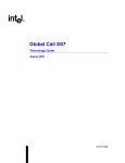
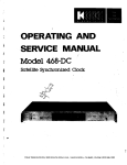
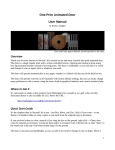
Scenario
Figure 1 illustrates an incoming call from the
circuit-switched network being answered by an
SMS-enabled voice mail system. After normal
call processing (that is, recording the message
left by the calling party), the voice mail system
notifies the called user that he/she has a
pending message by delivering a Short
Message (SM) to his/her cell phone.
Assumptions and Objectives
The purpose of this application note is to guide
the reader, step by step, through the
installation, configuration, and compilation of an
SMS-enabled SS7 telephony application using
Intel NetStructure SS7 boards and system-level
1
SMS-Enabled
Voice Mail
2
6
SSP
VLR
7
MSC
3
4
5
HLR
Figure 1
1
The SMS services of the GSM-MAP protocol will be used in this application note. The main concepts will apply for the IS41 protocol.
The MAP Test Utility (MTU) and the MAP Test Responder (MTR) are example applications designed to demonstrate the use of the
GSM-MAP module from Intel, using the direct interface to the protocol module. Source code, makefile, and the User’s Manual are available
(contact Technical Support).
3 The Call Test Utility (CTU) is an example application designed to demonstrate the use of the telephony modules from Intel (e.g., ISUP and
TUP) using the direct interface to the protocol module. Source code, makefile, and the User’s Manual are available (contact
Technical Support).
2
1
Enabling SMS in SS7 Telephony Applications Using Intel® NetStructure™ SS7 Boards
and Signaling Gateways
Application Note
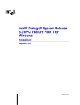
SMS-Enabled
Telephony Application
CIC1-31
MAP Link
Point
Code #1
ISUP Circuits
ISUP Link
SSP
VLR
MSC
Point Code #3
Point Code #2
Figure 2
Under normal conditions, these steps occur.
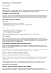
Reference System
1. User A calls User B who is not able to take
that call (e.g., already in a call).
To simulate the components involved in the
previous scenario, two systems were
constructed, each running Microsoft Windows*
20005 and containing an Intel NetStructure
SPCI4 board. One chassis hosts the actual
SMS-enabled telephony application (point
code 1), while the other one simulates the
MSC/VLR (point code 2). To keep the
configuration simple, the SSP (point code 3) is
hosted by the chassis running the telephony
application; calls will be made between these
two point codes using a loop back connection. For simplicity, point codes 2 (MSC/VLR)
and 3 (SSP) are only set up for testing
purposes and are not pieces of the system
and service that this application note is
intended to describe6. For further simplicity, no
location query will be sent to the HLR (this can
be easily achieved by adding this service
request into the MTU application). More
information on the actual HLR interrogation
procedure is available in this document.
2. User A’s local exchange or Service
Switching Point (SSP) routes the call to
User B’s voice mail service node.
3. The voice mail system records User A’s
message and releases that call. All this is
usually done using the ISUP (or TUP)
protocol4.
4. The voice mail queries User B’s Home
Location Register (HLR) for User B’s
current location within the wireless network.
User B’s mobile subscriber number is used
to retrieve the HLR point code to send a
MAP_SEND_ROUTING_INFO_FOR_SM
message.
5. The HLR sends the requested information
back to the voice mail service node in a
MAP_SEND_ROUTING_INFO_FOR_
SM_ACK message.
6. The voice mail formats and sends the short
message to the MSC/VLR currently visited
by User B using a MAP_FORWARD_
SHORT_MESSAGE message.
7. Once the short message has been
delivered to User B’s cell phone, the
MSC/VLR sends a MAP_FORWARD_
SHORT_MESSAGE_ACK back to the
voice mail system.
4
Components
The following components were included in
the reference system, based on the Intel
NetStructure SPCI4 board. Other products,
such as the Intel NetStructure PCCS6 board
or an Intel NetStructure Signaling Interface Unit
(SIU131/231/520), could be used alternatively.
Configuration files must be modified
accordingly.
It is also possible to build a voice mail application using the services of the INAP protocol.
It is possible to duplicate this configuration on a system based on the Linux* operating system, using the components listed in the
“Components” section.
6 In a real deployment, the SSP, HLR, and MSC/VLR are external network nodes managed by the network operator.
5
2
Enabling SMS in SS7 Telephony Applications Using Intel® NetStructure™ SS7 Boards
and Signaling Gateways
Hardware
■ Industrial chassis with PCI bus based on the
Intel® Pentium® III processor
■
Intel NetStructure SPCI4 SS7 board
■
MTP3 license button for SPCI4
■
Intel® Dialogic® DM/V1200-4E1-PCI voice
board (optional7)
■
Software
■ Install the SS7 Development Package.
(Please refer to the Installation section in the
SS7 Programmer’s Manual for Septel cP /
Septel PCI at http://resource.intel.com/
telecom/support/ss7/downloads/index.htm
for detailed installation instructions.)
■
Copy the SS7 binary for the SPCI4 (ss7.dc3)
and the host protocols (isp_lnx, scp_lnx,
tcp_lnx, and map_lnx for Linux; isp_nt.exe,
scp_nt.exe, tcp_nt.exe, and map_nt.exe for
Windows) in the directory where you installed
the Development Package (e.g., /usr/septel
on Linux and c:\septel on Windows).
■
Also extract the User Part Development
package in that same directory.
Two E-1/T-1 crossed cables
Software
RedHat* Linux 7.2 or 7.3
■ SS7 Development Package 2.02 for Linux
■
SS7 binary for SPCI4 v1.03
■
Host protocols for Linux: ISUP, SCCP, TCAP,
and MAP
■
User Part Development Package
■
Intel Dialogic System Release 5.1 FP1 for
Linux (optional8)
Windows 2000
■ SS7 Development Package 2.01 for
Windows
■
SS7 binary for SPCI4 v1.03
■
Host protocols for Windows: ISUP, SCCP,
TCAP, and MAP
■
User Part Development Package
■
Intel Dialogic System Release 5.1.1 FP1 for
Windows (optional8)
Application Note
If needed, install Intel Dialogic System Release.
For Linux, the LiS package needs to be
installed prior to installing the System Release.
Please refer to System Release 5.1 for Linux
Feature Pack 1 Release Notes at
http://resource.intel.com/telecom/support/
releases/unix51/linux51fp1/Onldoc/
index.html for details on this. For Windows,
the Java* Runtime Environment must be
installed before installing the System Release.
Please refer to System Release 5.1.1 for
Windows Service Pack 1 Release Notes at
http://resource.intel.com/telecom/support/
releases/winnt/SR511FP1/onldoc/htmlfiles/
index.html for details on this.
System Configuration
System Installation
Hardware
■ Boards must be inserted in each chassis.
Please refer to the corresponding User
Manual for guidance on this.
■
Connect the two chassis with an E-1/T-1
cross cable from the first Line Interface Unit
(LIU) of each Intel NetStructure SS7 board.
■
On the chassis running the SMS-enabled
telephony application, cross-connect the
second LIU to the third LIU of the SS7 board.
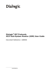
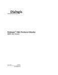
Figure 3 depicts the different SS7 protocol
layers involved when enabling SMS in a
telephony application.
The right side of Figure 3 shows the protocols
needed for the telephony (circuit-oriented) part
of the application. Depending on the country,
either ISUP or TUP will be used. The application developer can decide to directly interface
the ISUP (or TUP) module or may use Global
Call to deal with calls. Configuration files will be
slightly different when Global Call is used.
Please refer to the Global Call SS7 Technology
7
The Intel Dialogic DM/V1200-4E1 voice board is necessary if the telephony application needs to perform some media processing
(e.g., playing prompts, detecting DTMF digits, etc.). Note that another media resource card such as an Intel Dialogic D/300JCT-E1
combined media board could be used alternatively.
8 The Intel Dialogic System Release is needed only if an Intel Dialogic board and/or Global Call is used.
3
Enabling SMS in SS7 Telephony Applications Using Intel® NetStructure™ SS7 Boards
and Signaling Gateways
Application Note
SMS-Enabled
Telephony Application
MAP
Global Call
TCAP
ISUP
TUP
SCCP
MMTP Layer 3
MMTP Layer 2
MMTP Layer 1
Figure 3
User’s Guide for Linux and Windows at
http://resource.intel.com/telecom/support/
releases/winnt/SR511FP1/onldoc/htmlfiles/
index.html for more details on this.
The left side of Figure 3 shows the non-circuit
related protocols that are needed to bring
SMS into a telephony application. The SMS
service is provided by the Mobile Application
Part (MAP) which relies on the services provided by the Transaction Capability Application
Part (TCAP) which itself uses the services of
the Signaling Connection Control Part (SCCP).
Hence, these three different protocols must be
running and properly configured.
The software environment is controlled by
system.txt. The reference system uses
host-based protocols and hence the
corresponding modules must be declared as
9
4
LOCAL and must be forked using the
FORK_PROCESS command in system.txt.
Configuration of MTP and ISUP is done within
config.txt. On both systems, MTP_USER_PART
must be invoked to register SCCP module
(id 0x33) as a user part with Service Indicator
0x3 (this is, SCCP).
SCCP, TCAP, and MAP are configured using
discrete messages. It is important to properly
configure the local subsystem and remote
subsystem numbers9 on both sides as well as
bringing them into service. For this purpose,
the scripts mtucfg.ms7 and mtrcfg.ms7 can
be sent to the board using s7_play on point
code 1 and point code 2 respectively. Please
refer to the MAP Test Utility (MTU) and
Responder (MTR) User Guide for details on this.
Local and remote subsystem numbers are to be specified by the network operator. In wireless networks, MSCs usually have subsystem
number 0x08.
Enabling SMS in SS7 Telephony Applications Using Intel® NetStructure™ SS7 Boards
and Signaling Gateways
Application Note
System.txt Files
System containing the SMS-enabled application
*
* System.txt for the Intel NetStructure Windows Development
* Package.
*
*
* Essential modules running on host:
*
LOCAL
0x20
* ssd/ssds - Board interface task
LOCAL
0x00
* tim_nt - Timer task
LOCAL
0xef
* s7_log - SS7 message display task
*
* Optional modules running on the host:
*
LOCAL
0xcf
* s7_mgt - Management/config task
LOCAL
0x33
* SCCP module
LOCAL
0x14
* TCAP module
LOCAL
0x15
* MAP module
LOCAL
0x23
* ISUP module
*
* Application modules
*
LOCAL
0x2d
* SMS-enabled CTU
*
* Modules running on the board (all redirected via ssd):
*
REDIRECT
0x22 0x20 * MTP3 module
REDIRECT
0x71 0x20 * MTP2 module
REDIRECT
0x10 0x20 * CT bus/Clocking control module
REDIRECT
0x8e 0x20 * On-board management module
*
* Redirection of status indications:
*
REDIRECT
0xdf 0xef * LIU/MTP2 status messages -> s7_log
REDIRECT
0x9e 0xef *
*
* Now start-up all local tasks:
*
(For Septel ISA (PCCS6) start-up ssd and ssd_poll,
*
for Septel cP / PCI start-up ssds)
*
* FORK_PROCESS
ssd.exe
* FORK_PROCESS
ssd_poll.exe
FORK_PROCESS
ssds.exe
FORK_PROCESS
tim_nt.exe
FORK_PROCESS
tick_nt.exe
FORK_PROCESS
scp_nt.exe
FORK_PROCESS
tcp_nt.exe
FORK_PROCESS
map_nt.exe
FORK_PROCESS
isp_nt.exe
FORK_PROCESS
s7_mgt.exe
FORK_PROCESS
s7_log.exe
*
5
Application Note
Enabling SMS in SS7 Telephony Applications Using Intel® NetStructure™ SS7 Boards
and Signaling Gateways
System simulating the MSC/VLR
*
* System.txt for the Intel NetStructure Windows Development
* Package.
*
*
* Essential modules running on host:
*
LOCAL
0x20
* ssd/ssds - Board interface task
LOCAL
0x00
* tim_nt - Timer task
LOCAL
0xef
* s7_log - SS7 message display task
*
* Optional modules running on the host:
*
LOCAL
0xcf
* s7_mgt - Management/config task
LOCAL
0x33
* SCCP module
LOCAL
0x14
* TCAP module
LOCAL
0x15
* MAP module
*
* Application modules
*
LOCAL
0x2d
* MTR
*
* Modules running on the board (all redirected via ssd):
*
REDIRECT
0x22 0x20 * MTP3 module
REDIRECT
0x71 0x20 * MTP2 module
REDIRECT
0x10 0x20 * CT bus/Clocking control module
REDIRECT
0x8e 0x20 * On-board management module
*
* Redirection of status indications:
*
REDIRECT
0xdf 0xef * LIU/MTP2 status messages -> s7_log
REDIRECT
0x9e 0xef *
*
* Now start-up all local tasks:
*
(For Septel ISA (PCCS6) start-up ssd and ssd_poll,
*
for Septel cP / PCI start-up ssds)
*
* FORK_PROCESS
ssd.exe
* FORK_PROCESS
ssd_poll.exe
FORK_PROCESS
ssds.exe
FORK_PROCESS
tim_nt.exe
FORK_PROCESS
tick_nt.exe
FORK_PROCESS
scp_nt.exe
FORK_PROCESS
tcp_nt.exe
FORK_PROCESS
map_nt.exe
FORK_PROCESS
s7_mgt.exe
FORK_PROCESS
s7_log.exe
*
6
Enabling SMS in SS7 Telephony Applications Using Intel® NetStructure™ SS7 Boards
and Signaling Gateways
Application Note
Config.txt Files
System containing the SMS-enabled application
*
*
*
*
*
Configure individual boards:
For Septel ISA (PCCS6) boards:
PCCS6_BOARD <port_id> <board_id> <num_pcm> <flags> <code_file>
PCCS6_BOARD 0 0 0 0x0043 mtp76.dc2
* For Septel cP / PCI boards:
* SEPTELCP_BOARD <board_id> <flags> <code_file>
SEPTELPCI_BOARD 0 0x0042 ss7.dc3 MTP
* Configure individual E1/T1 interfaces:
* LIU_CONFIG <board_id> <liu_id> <liu_type> <line_code> <frame_format>
*
<crc_mode>
LIU_CONFIG 0 0 5 1 1 1
LIU_CONFIG 0 1 5 1 1 1
LIU_CONFIG 0 2 5 1 1 1
* MTP parameters:
* MTP_CONFIG <reserved> <reserved> <options>
MTP_CONFIG 0 0 0x0000
* Define linksets:
* MTP_LINKSET <linkset_id> <adjacent_spc> <num_links> <flags>
<local_spc> <ssf>
MTP_LINKSET 0 2 1 0x0000 1 0x08
MTP_LINKSET 1 3 1 0x0000 1 0x08
MTP_LINKSET 2 1 1 0x0000 3 0x08
* Define signaling links:
* MTP_LINK <link_id> <linkset_id> <link_ref> <slc> <board_id>
<blink>
*
<stream> <timeslot> <flags>
* (Note: For Septel ISA (PCCS6) boards the first LIU port is
stream=16
* whilst for Septel cP / PCI boards the first LIU port is stream=0)
MTP_LINK 0 0 0 0 0 0 0 16 0x0006
MTP_LINK 1 1 0 0 0 1 1 16 0x0006
MTP_LINK 2 2 0 0 0 2 2 16 0x0006
* Define a route for each remote signaling point:
* MTP_ROUTE <dpc> <linkset_id> <user_part_mask>
MTP_ROUTE 2 0 0x0008
MTP_ROUTE 1 2 0x0020
MTP_ROUTE 3 1 0x0020
* Define any user provided Layer 4 protocol:
* MTP_USER_PART <service_ind> <module_id>
MTP_USER_PART 0x03 0x33
7
Application Note
Enabling SMS in SS7 Telephony Applications Using Intel® NetStructure™ SS7 Boards
and Signaling Gateways
* ISUP parameters:
* Configure ISUP module:
* ISUP_CONFIG <reserved> <reserved> <user_id> <options> <num_grps>
<num_ccts>
ISUP_CONFIG 0 0 0x2d 0x0435 4 128
* Configure ISUP circuit groups:
* ISUP_CFG_CCTGRP <gid> <dpc> <base_cic> <base_cid> <cic_mask>
<options>
*
<user_inst> <user_id> <opc> <ssf> <variant> <options2>
ISUP_CFG_CCTGRP 0 3 0x01 0x01 0x7fff7fff 0x001c 0 0x2d
0x8 0 0x00
ISUP_CFG_CCTGRP 1 1 0x01 0x21 0x7fff7fff 0x001c 0 0xef
0x8 0 0x00
8
1
3
Enabling SMS in SS7 Telephony Applications Using Intel® NetStructure™ SS7 Boards
and Signaling Gateways
Application Note
System simulating the MSC/VLR
*
*
*
*
*
Configure individual boards:
For Septel ISA (PCCS6) boards:
PCCS6_BOARD <port_id> <board_id> <num_pcm> <flags> <code_file>
PCCS6_BOARD 0 0 0 0x0043 mtp76.dc2
* For Septel cP / PCI boards:
* SEPTELCP_BOARD <board_id> <flags> <code_file>
SEPTELPCI_BOARD 0 0x0043 ss7.dc3 MTP
* Configure individual E1/T1 interfaces:
* LIU_CONFIG <board_id> <liu_id> <liu_type> <line_code> <frame_format>
*
<crc_mode>
LIU_CONFIG 0 0 5 1 1 1
* MTP parameters:
* MTP_CONFIG <reserved> <reserved> <options>
MTP_CONFIG 0 0 0x0000
* Define linksets:
* MTP_LINKSET <linkset_id> <adjacent_spc> <num_links> <flags>
<local_spc> <ssf>
MTP_LINKSET 0 1 1 0x0000 2 0x08
* Define signaling links:
* MTP_LINK <link_id> <linkset_id> <link_ref> <slc> <board_id>
<blink>
*
<stream> <timeslot> <flags>
* (Note: For Septel ISA (PCCS6) boards the first LIU port is
stream=16
* whilst for Septel cP / PCI boards the first LIU port is stream=0)
MTP_LINK 0 0 0 0 0 0 0 16 0x0006
* Define a route for each remote signaling point:
* MTP_ROUTE <dpc> <linkset_id> <user_part_mask>
MTP_ROUTE 1 0 0x0008
* Define any user provided Layer 4 protocol:
* MTP_USER_PART <service_ind> <module_id>
MTP_USER_PART 0x03 0x33
9
Application Note
Enabling SMS in SS7 Telephony Applications Using Intel® NetStructure™ SS7 Boards
and Signaling Gateways
Proving the Configuration
First of all, verify that MTP is properly configured. To do this, run gctload on each system and
then activate all the signaling links using mtpsl. This is the output of s7_log on the system
running the telephony application:
…
S7L:I0000 MTP Event : linkset_id/link_ref=0000 Changeback
S7L:I0000 MTP Event : linkset_id=00 Link set recovered
S7L:I0000 MTP Event : linkset_id=00 Adjacent SP accessible
S7L:I0000 MTP Event : point code=00000002
Destination available
S7L:I0000 MTP Event : linkset_id/link_ref=0100 Changeback
S7L:I0000 MTP Event : linkset_id=01 Link set recovered
S7L:I0000 MTP Event : linkset_id=01 Adjacent SP accessible
S7L:I0000 MTP Event : point code=00000003
Destination available
S7L:I0000 MTP Event : linkset_id/link_ref=0200 Changeback
S7L:I0000 MTP Event : linkset_id=02 Link set recovered
S7L:I0000 MTP Event : linkset_id=02 Adjacent SP accessible
S7L:I0000 MTP Event : point code=00000001
Destination available
Once MTP configuration has been proved, the ISUP configuration can be checked. This can be
easily done by running the CTU demo on the system where it has been configured. Please refer to
the Call Test Utility (CTU) User Guide to get details on how to compile and run the CTU application. Similarly, the MAP configuration can be proved by running the MTU demo on the chassis
hosting point code 1 and the MTR demo on the other chassis (which simulates the MSC/VLR).
SMS-enabling the Call Test Utility
Now that all pieces are correctly installed and configured, the final objective of this application
note is to SMS-enable a telephony application. In our particular case, we will merge the code of
the MAP Test Utility (which demonstrates SMS forwarding functionality) with the code of the Call
Test Utility.
Here is the process.
1. Copy all the MTU files in the CTU directory.
2. Add the MTU object files in the CTU makefile. For example, in ctu.mnt
OBJS = ctu.obj call.obj digpack.obj ctu_main.obj mtu.obj mtu_fmt.obj
mtu_main.obj
10
Enabling SMS in SS7 Telephony Applications Using Intel® NetStructure™ SS7 Boards
and Signaling Gateways
Application Note
3. Delete the entire contents of mtu_main.c and copy and paste the following simplified code10:
#include “mtu.h”
/*
* Default values for MTU’s command line options:
*/
#define DEFAULT_MODULE_ID
(0x2d)
#define DEFAULT_MAP_ID
(MAP_TASK_ID)
#define DEFAULT_OPTIONS
(0x000f)
#define DEFAULT_MAX_ACTIVE (0)
/*
* Structure that stores the data entered on the command
line
*/
static CL_ARGS cl_args;
void mtu_ForwardSMS()
{
cl_args.mtu_mod_id = DEFAULT_MODULE_ID;
cl_args.mtu_map_id = DEFAULT_MAP_ID;
cl_args.map_version = MTU_MAPV2;
cl_args.mode = MTU_FORWARD_SM;
cl_args.options = DEFAULT_OPTIONS;
cl_args.base_dlg_id = BASE_DLG_ID;
cl_args.num_dlg_ids = NUM_OF_DLG_IDS;
cl_args.max_active = DEFAULT_MAX_ACTIVE;
cl_args.imsi = “486528837”;
cl_args.orig_address = “43010008”;
cl_args.service_centre = “”;
cl_args.dest_address = “43020008”;
cl_args.message = “Hello World”;
cl_args.msisdn = “”;
cl_args.ggsn_number = “”;
mtu_ent(&cl_args);
}
4. In ctu.c, declare the prototype of the above defined function (this is, void mtu_ForwardSMS()).
Upon receipt of an incoming call indication (this is, in the ctu_incomingcall() function), call
mtu_ForwardSMS() function (instead of placing an outgoing call).
static int CTU_incoming_call(call, cid)
CTU_CALL *call;
/* per call data structure
*/
u16
cid;
/* logical circuit id */
{
CTU_CALL *og_call;
10
The originating address and destination address the cl_args structure in the mtu_ForwardSMS need to be set according to
your configuration.
11
Enabling SMS in SS7 Telephony Applications Using Intel® NetStructure™ SS7 Boards
and Signaling Gateways
Application Note
print_call(“IC”, call, cid);
/*
* Check to see if the cpc value matches
* that for calls that we will answer.
*/
if (call->cpc == REJECT_CPC)
{
CTU_release_req(IC_ID(cid), call->instance,
CAUSEV_NULL);
CTU_call_idle(call);
call->state = STATE_WAIT_IDLE;
}
else
{
/*
* Complete the incoming call setup:
*/
CTU_alert_req(IC_ID(cid), call->instance);
CTU_setup_resp(IC_ID(cid), call->instance);
call->state = STATE_IC_ACTIVE;
mtu_ForwardSMS();
}
return(0);
}
5. Recompile the enhanced CTU program.
HLR Interrogation
When an SMS-enabled service node tries to
send a message to a mobile phone, it must
first identify where that mobile is. This is
achieved by querying the mobile’s HLR for
location information. In some cases, the point
code of a given operator’s HLR is locally
known, in other cases it is not. This will obviously be true when the mobile phone is bound
to a foreign operator. This leads to two different ways of performing HLR interrogation:
direct and indirect.
Direct HLR Interrogation
Direct HLR interrogation occurs when the point
code of a given mobile phone’s HLR is known
in the local service node. For every HLR that
can be directly addressed, the following
command must be added in the local
config.txt:
11
12
■
MTP_ROUTE with <dpc> set the HLR’s point
code and <user_part_mask> set to 0x8
Using s7_play11, a set of discrete messages
need to be sent to SCCP to configure the
point code and subsystem number of the
remote HLR(s):
■
SCP_MSG_CNF_SSR (0x7741) with
<ssr_type> set to RSP and <spc> to the
actual HLR’s point code
■
SCP_MSG_CNF_SSR (0x7741) with
<ssr_type> set to RSS, <spc> to the actual
HLR’s point code, and <ssn> to 0x6 (which
is usually the reserved SSN value for HLR)
Please refer to the SCCP Programmer’s
Manual at http://resource.intel.com/
telecom/support/ss7/downloads/index.htm
for more details on SCCP configuration.
The destination address of the dialogue in
Note that for an SIU-based service node, the following commands are available in config.txt to configure the Remote Signaling Point and
the Remote Subsystems: SCCP_RSP and SCCP_RSS. Please refer to the Intel NetStructure SIU520 Developer’s Manual for more details
on these commands.
Enabling SMS in SS7 Telephony Applications Using Intel® NetStructure™ SS7 Boards
and Signaling Gateways
which the “Send Location Information for SM”
will be sent must contain the point code of the
HLR, as well as the SSN. This address must
be encoded with the Q.713 definition of
“Called party address”, starting with the
address indicator (set to 0x43 ) and containing
signaling point code and subsystem number
(set to 0x06 for HLR)12.
Indirect HLR Interrogation
When the HLR’s point code is not known to
the Service Node, Global Title Translation
(GTT) is needed in order to properly route the
location information query to the remote HLR.
The Global Title will be the mobile number
itself and the location request (Send Routing
Info for SM) must be sent to a GTT-capable
node within the SS7 network. To make this
node known to the local stack, the following
command must be added in the local
config.txt:
■
MTP_ROUTE with <dpc> set to the point
code of the node that performs GTT
It is also necessary to configure the point code
of this GTT node in the local SCCP by sending
the following message (for example, using
s7_play):
■
SCP_MSG_CNF_SSR (0x7741) with
<ssr_type> set to RSP and <spc> to the
point code of the node that performs GTT
The destination address of the dialogue in
which the “Send Location Information for SM”
will be sent must contain the point code of the
node performing GTT, as well as the actual
Global Title. This address must be encoded
with the Q.713 definition of “Called party
address”. For the Address Indicator,
■
Bit 1 must be set to 1 (to indicate the
address contains signaling point code)
■
Bit 2 must be set to 0 (to indicate the address
does not contain any subsystem number)
■
Bits 3-6 (known as the Global Title Indicator)
must reflect the contents of the actual Global
Title in the address (translation type,
numbering plan, …)
12
■
Bit 7 must be set to 1 (to indicate that routing must be performed based on Global
Title)
■
Bit 8 is set to 0 on an international network
(check this with the operator)
Application Note
For both methods, a MAP dialogue must be
established with the peer entity (the HLR itself
or the node performing GTT). Within this
dialogue, a MAP-SEND-ROUTING-INFOFORSM-REQ service primitive must be sent.
Please refer to the MAP Programmer’s Manual
at http://resource.intel.com/telecom/
support/ss7/downloads/index.htm for
details about the specific parameters that
must be set in this service primitive.
Definitions and Acronyms
CTU (Call Test Utility) — Example application
designed to demonstrate the use of the Intel
NetStructure telephony modules (e.g., ISUP,
TUP and NUP) using the direct interface to the
protocol module.
HLR — Home Location Register
ISUP — ISDN User Part
MAP — Mobile Application Part
MSC — Mobile Switching Centre
MTR (MAP Test Responder) — Example application designed to demonstrate the use of the
Intel NetStructure MAP module, using the
direct interface to the protocol module.
MTU (MAP Test Utility) — Example application
designed to demonstrate the use of the Intel
NetStructure MAP module, using the direct
interface to the protocol module.
SMS (Short Message Service) — Service for
sending messages of up to 160 characters to
mobile phones.
SSP (Service Switching Point) — SSPs are
switches that originate, terminate, or tandem
calls. An SSP sends signaling messages to
other SSPs to setup, manage, and release
voice circuits required to complete a call.
VLR — Visitor Location Register
For example, the destination address is 0x43020006 if the point code of the HLR is 0x02.
13
To learn more, visit our site on the World Wide Web at
http://www.intel.com.
1515 Route Ten
Parsippany, NJ 07054
Phone: 1-973-993-3000
INFORMATION IN THIS DOCUMENT IS PROVIDED IN CONNECTION WITH INTEL® PRODUCTS. NO LICENSE, EXPRESS OR
IMPLIED, BY ESTOPPEL OR OTHERWISE, TO ANY INTELLECTUAL PROPERTY RIGHTS IS GRANTED BY THIS DOCUMENT.
EXCEPT AS PROVIDED IN INTEL’S TERMS AND CONDITIONS OF SALE FOR SUCH PRODUCTS, INTEL ASSUMES NO
LIABILITY WHATSOEVER, AND INTEL DISCLAIMS ANY EXPRESS OR IMPLIED WARRANTY, RELATING TO SALE AND/OR USE OF
INTEL PRODUCTS INCLUDING LIABILITY OR WARRANTIES RELATING TO FITNESS FOR A PARTICULAR PURPOSE,
MERCHANTABILITY, OR INFRINGEMENT OF ANY PATENT, COPYRIGHT OR OTHER INTELLECTUAL PROPERTY RIGHT.
Intel products are not intended for use in medical, life saving, life sustaining, critical control or safety systems, or in nuclear facility
applications.
Intel may make changes to specifications, product descriptions, and plans at any time, without notice.
Intel, Intel Dialogic, Intel NetStructure, Pentium, and the Intel logo are trademarks or registered trademarks of Intel Corporation or
its subsidiaries in the United States and other countries.
*Other names and brands may be claimed as the property of others.
Performance tests and ratings are measured using specific computer systems and/or components and reflect the approximate
performance of Intel products as measured by those tests. Any difference in system hardware or software design or configuration
may affect actual performance. Buyers should consult other sources of information to evaluate the performance of systems or
components they are considering purchasing. For more information on performance tests and on the performance of Intel products,
reference http://www.intel.com/performance/resources/Limits.htm or call (U.S.) 1-800-628-8686 or 1-916-356-3104.
Printed in the USA
Copyright © 2003 Intel Corporation
All rights reserved.
e Printed on recycled paper.
09/03
00-8775-001