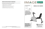
1
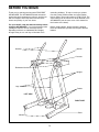
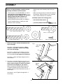
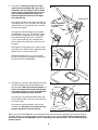
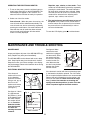
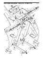
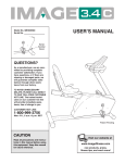
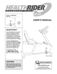
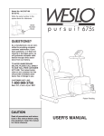
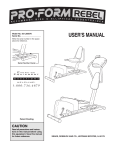
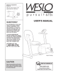
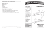
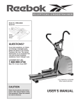
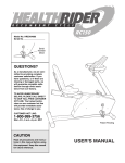
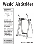
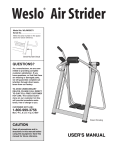
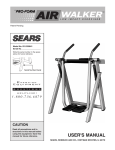
ª
Model No. PFMC77755
Serial No.
Write the serial number in the space
above for future reference.
Serial Number Decal (under console)
QUESTIONS?
As a manufacturer, we are committed to providing complete
customer satisfaction. If you
have questions, or find that there
are missing or damaged parts,
we will guarantee complete satisfaction through direct assistance from our factory.
TO AVOID UNNECESSARY
DELAYS, PLEASE CALL DIRECT
TO OUR TOLL-FREE CUSTOMER
HOT LINE. The trained technicians on our customer hot line
will provide immediate assistance, free of charge to you.
CUSTOMER HOT LINE:
1-800-999-3756
Mon.ÐFri., 6 a.m.Ð6 p.m. MST
CAUTION
Patent Pending
Read all precautions and instructions in this manual before
using this equipment. Save this
manual for future reference.
USER'S MANUAL
TABLE OF CONTENTS
IMPORTANT PRECAUTIONS . . . . . . . . . . . . . . . . . . . . . . . . . . . . . . . . . . . . . . . . . . . . . . . . . . . . . . . . . . . . .2
BEFORE YOU BEGIN . . . . . . . . . . . . . . . . . . . . . . . . . . . . . . . . . . . . . . . . . . . . . . . . . . . . . . . . . . . . . . . . . . .3
ASSEMBLY . . . . . . . . . . . . . . . . . . . . . . . . . . . . . . . . . . . . . . . . . . . . . . . . . . . . . . . . . . . . . . . . . . . . . . . . . . .4
HOW TO USE THE AIR WALKER . . . . . . . . . . . . . . . . . . . . . . . . . . . . . . . . . . . . . . . . . . . . . . . . . . . . . . . . . .7
MAINTENANCE AND TROUBLE-SHOOTING . . . . . . . . . . . . . . . . . . . . . . . . . . . . . . . . . . . . . . . . . . . . . . . . .8
CONDITIONING GUIDELINES . . . . . . . . . . . . . . . . . . . . . . . . . . . . . . . . . . . . . . . . . . . . . . . . . . . . . . . . . . . . .9
PART LIST . . . . . . . . . . . . . . . . . . . . . . . . . . . . . . . . . . . . . . . . . . . . . . . . . . . . . . . . . . . . . . . . . . . . . . . . . . .10
EXPLODED DRAWING . . . . . . . . . . . . . . . . . . . . . . . . . . . . . . . . . . . . . . . . . . . . . . . . . . . . . . . . . . . . . . . . .11
ORDERING REPLACEMENT PARTS . . . . . . . . . . . . . . . . . . . . . . . . . . . . . . . . . . . . . . . . . . . . . . . .Back Cover
LIMITED WARRANTY . . . . . . . . . . . . . . . . . . . . . . . . . . . . . . . . . . . . . . . . . . . . . . . . . . . . . . . . . . .Back Cover
IMPORTANT PRECAUTIONS
WARNING: To reduce the risk of serious injury, read the following important precautions before
using the AIR WALKER.
wear athletic shoes for foot protection when
exercising.
1. It is the responsibility of the owner to ensure
that all users of the AIR WALKER are adequately informed of all warnings and precautions.
10. When you are getting onto and off the AIR
WALKER, always tighten the resistance
knobs, hold the handles firmly, and be sure
that your body weight is centered directly
over the pedals.
2. Read all instructions in this manual before
using the AIR WALKER.
3. Use the AIR WALKER only on a level surface.
Cover the floor beneath the AIR WALKER to
protect the floor or carpet.
11. Use the AIR WALKER only as described in
this manual.
12. If you feel faint, dizzy, or short of breath while
exercising, stop immediately and begin cooling down.
4. Be sure that there are no obstacles in front of
or behind the AIR WALKER.
5. Inspect and tighten all parts regularly.
Replace any worn parts immediately.
13. The following precautions are printed on the
electronic monitor: Read UserÕs Manual
before operating; To enter and exit, tighten
resistance knobs, grasp handles, and place
body directly over foot pedals; Stop if you
feel faint, dizzy, or short of breath; Keep children away.
6. Keep children and pets away from the AIR
WALKER at all times.
7. The AIR WALKER should not be used by persons weighing more than 250 pounds.
8. Keep hands and feet away from moving parts.
14. The AIR WALKER is intended for home use
only. Do not use the AIR WALKER in any
commercial, rental, or institutional setting.
9. Do not wear loose clothing that could
become caught on the AIR WALKER. Always
WARNING: Before beginning this or any exercise program, consult your physician. This is especially
important for persons over the age of 35 or persons with pre-existing health problems. Read all
instructions before using. ICON assumes no responsibility for personal injury or property damage
sustained by or through the use of this product.
2
BEFORE YOU BEGIN
Thank you for selecting the innovative PROFORM¨
AIR WALKER. The AIR WALKER blends advanced
engineering with contemporary styling to provide you
with a no-impact, total body workout in the convenience and privacy of your own home.
(excluding holidays). To help us assist you, please
note the product model number and serial number
before calling. The model number is PFMC77755. The
serial number can be found on a decal attached to the
AIR WALKER (see the front cover of this manual for
the location of the decal).
For your benefit, read this manual carefully before
using the AIR WALKER. If you have questions after
reading the manual, call our Customer Service
Department toll-free at 1-800-999-3756, Monday
through Friday, 6 a.m. until 6 p.m. Mountain Time
Before reading further, please review the drawing
below and familiarize yourself with the parts that are
labeled.
Handles
Monitor
Console
Resistance Knobs
Uprights
Legs
Pedals
LEFT SIDE
RIGHT SIDE
Base
Wheels
3
ASSEMBLY
Before you begin assembly, carefully read the
following information and instructions:
¥ Read through each assembly step before you
begin.
¥ Place all parts of the AIR WALKER in a cleared
area and remove the packing materials.
IMPORTANT: DO NOT REMOVE THE RUBBER
BANDS FROM THE HUB COVERS (see
assembly step 5). Do not dispose of any
packing materials until assembly is completed.
¥ Make sure that all parts are oriented as shown in
the drawings. Tighten all parts as you assemble
them, unless instructed to do otherwise.
Assembly requires the following tools:
¥ the included allen wrench
¥ Use the drawings below to identify the small
hardware used in assembly.
¥ your own phillips screwdriver
2 1/4" Lower Screw (26)Ð2
3/8" x 1" Screw (24)Ð8
2" Upper Screw (25)Ð2
#8 x 1/2" Screw (31)Ð8
3/8" Curved Washer (27)Ð4
1. Before you begin, read the information at the
top of this page.
Fig. 1
ÒTOP RIGHTÓ
Sticker
ÒTOP LEFTÓ
Sticker
See figure 1. Find the Left Upright (3). Note:
There is a ÒTOP LEFTÓ sticker on the upper
end of the Left Upright.
4
3
See figure 1. Slide the Left Upright (3) onto the
Base (1). Thread two 3/8Ó x 1Ó Screws (24) into
the Left Upright. Do not tighten the Screws yet.
24
See figure 1. Attach the Right Upright (4) in the
same manner.
1
2. See figure 2. Hold the Top Frame (2) level, and
insert it into the Left and Right Uprights (3 and 4).
Note: It may be helpful to rock the Top Frame
from side to side slightly as you insert it.
Make sure that the indicated rubber bands are
not pinched between the Top Frame and the
Uprights. Attach the Top Frame with four 3/8Ó x 1Ó
Screws (24).
Fig. 2
2
Rubber
Band
See figures 1 and 2. Tighten the eight 3/8Ó x 1Ó
Screws (24).
24
24
24
3
4
Rubber
Band
4
3. See figure 3b. Find the Right Leg (7). Note: The
Right Leg is marked with a ÒRIGHTÓ sticker.
Set a Pedal (28) on the plate at the lower end of
the Right Leg. Note: Be careful not to attach
the Pedal backwards. Look at the curve of the
Right Leg and the front end of the Pedal to
make sure that the Pedal is turned correctly.
Fig. 3a
31
Fig. 3b
See figure 3a. Turn the Right Leg (7) and the
Pedal (28) upside-down as shown. Attach the
Pedal with four #8 x 1/2Ó Screws (31).
7
28
ÒRIGHTÓ
Sticker
Right Leg
Curves in This
Direction
7
Front
End
28
4. See figure 4. Look into the upper end of the
Right Leg (7) and make sure that the Plastic
Sleeve (41) is fully inserted.
Fig. 4
ÒRIGHTÓ
Sticker
See figure 4. Find the Right Handle (11). Note:
The Right Handle is marked with a ÒRIGHTÓ
sticker. Insert the Right Handle into the Right
Leg (7).
11
See figure 4. Slide a 3/8Ó Curved Washer (27)
onto a 2Ó Upper Screw (25). Note: Use the
actual-size drawing to identify the 2Ó Upper
Screw (25). Insert the 2Ó Upper Screw into the
upper hole in the Right Leg (7) and the Right
Handle (11).
41
27
7
25
See figure 4. Slide a 3/8Ó Curved Washer (27)
onto a 2 1/4Ó Lower Screw (26). Note: Use the
actual-size drawing to identify the 2 1/4Ó
Lower Screw (26). Insert the 2 1/4Ó Lower
Screw into the lower hole in the Right Leg (7)
and the Right Handle (11).
26
ÒRIGHTÓ
Sticker
2Ó Upper Screw (25)
See figure 4. Make sure that the 2Ó Upper
Screw (25) is in the upper hole, and that the
2 1/4Ó Lower Screw (26) is in the lower hole.
The Screws must be inserted from the side
shown.
2 1/4Ó Lower Screw (26)
Note: This step requires one 2Ó Upper Screw (25)
and one 2 1/4Ó Lower Screw (26). The 2Ó Upper
Screw (25) must be in the upper hole; the 2 1/4Ó
Lower Screw (26) must be in the lower hole.
5
5. See figure 5a. Before you begin this step,
make sure that the Right Hub Cover (19) is
attached to the Top Frame (2) with a rubber
band as shown. If the Right Hub Cover has
come off during shipping, see figure 5b.
Slide the Right Hub Cover onto the Right
Pivot Bracket (20).
Fig. 5a
2
Rubber Band
See figure 5a. Find the two holes inside the slot
of the Right Hub Cover (19). Make sure that the
rubber band is not covering the holes, and that
the holes are aligned.
Note: Tighten the
2Ó Upper Screw
(25) first.
Hole
19
25
See figure 5a. Hold the Right Leg (7) against
the Right Hub Cover (19). Thread the 2Ó Upper
Screw (25) two complete turns into the upper
hole inside the Right Hub Cover. Thread the
2 1/4Ó Lower Screw (26) two complete turns
into the lower hole. Break and remove the rubber band.
Hole
26
7
Fig. 5b
See figure 5a. Fully tighten the 2Ó Upper Screw
(25). After the 2Ó Upper Screw is tightened, fully
tighten the 2 1/4Ó Lower Screw (26).
ÒRIGHTÓ
Sticker
Repeat assembly steps 3, 4, and 5 to attach
the Left Leg and the Left Handle (not shown) to
the left side of the AIR WALKER.
20
19
6. See figure 6a. Insert two ÒAAÓ batteries (not included) into the Monitor (39). Alkaline batteries are
recommended. Make sure that the negative (Ð)
ends of the batteries are touching the springs,
and that the positive (+) ends of the batteries
are pushed against the metal contacts.
Fig. 6a
Batteries
39
40
Fig. 6b
See figure 6a. Plug the Reed Switch Wire (44)
into the Monitor (39). Insert any excess wire into
the Console (40).
40
39
44
See figure 6b. Snap the Monitor (39) into the
Console (40). Be careful not to pinch the wire
between the Monitor and the Console.
Before you use the AIR WALKER, use the included allen wrench to firmly re-tighten all of the screws used in
assembly. Remove the orange and green identification stickers from the AIR WALKER. Note: During the first
few minutes that the AIR WALKER is used, a squeaking noise may be heard. This is normal during the
break-in period.
6
HOW TO USE THE AIR WALKER
ELECTRONIC MONITOR MODES
CAUTION: When you are getting onto and off
the AIR WALKER, always tighten the resistance knobs, hold the handles firmly, and be
sure that your body weight is centered directly over the pedals.
The simple-to-operate electronic monitor offers
five different modes to provide instant exercise
feedback. The five modes are described below:
Reps/minÑDisplays the number of repetitions you
are performing per minute.
EXERCISING ON THE AIR WALKER
RepsÑDisplays the total number of repetitions you
have completed, up to Ò999.Ó The display will then
reset to Ò0Ó and continue counting.
The proper form for exercising on the AIR WALKER
is similar to walkingÑmove one leg forward as you
move the other leg back. Never attempt to move
both legs in the same directionÑyou could be
injured, or the AIR WALKER could be damaged.
CaloriesÑDisplays the approximate number of
Calories you have burned. Note: If the resistance is
near the highest or lowest setting, the actual number
of Calories you have burned will be slightly higher or
lower than the number displayed.
For a full body workout, hold the handles as you walk,
moving your arms and legs in motion with the handles
and pedals. To vary the effect on your muscles,
change your stance on the AIR WALKER. For example, you can change the position of your hands on the
handles, or you can bend your legs slightly instead of
keeping them straight.
Scan AllÑDisplays the reps/min, reps, calories, and
time modes, for approximately 5 seconds each,
in a repeating cycle.
TimeÑDisplays the length of time you have exercised. Note: If you stop exercising for ten seconds or
longer, the time mode will pause until you resume.
For a lower body workout, rest your hands on the
edge of the console for balance as you walk on the
pedals. Note: Do not lean on the console. It is not
designed to support your body weight.
DIAGRAM OF THE ELECTRONIC MONITOR
RESISTANCE ADJUSTMENT
To vary the intensity of your workout, the resistance of
the AIR WALKER can be changed. To increase the
resistance, turn both resistance knobs clockwise. To
decrease the resistance, turn the resistance knobs
counterclockwise.
1
M
E
P
RE
S/
2
MI
N
3
LL
¥ R
NA
EPS
¥ CALORIES ¥ SCA
¥
TI
4
1. LCD displayÑDisplays all modes.
2. Mode indicatorsÑShow which mode has
been selected.
Resistance
Knobs
3. Mode buttonÑSelects all modes.
4. On/Clear buttonÑTurns the power on and
resets all modes.
7
OPERATING THE ELECTRONIC MONITOR
Reps/min, reps, calories, or time modeÑThese
modes can be individually selected by repeatedly
pressing the mode button. The mode indicators
will show which mode has been selected. (Make
sure that the scan all mode is not selected.) The
modes will be selected in the following order:
reps/min, reps, calories, scan all, time.
1. To turn on the power, press the on/clear button or
simply begin exercising on the AIR WALKER. The
entire display will appear for two seconds. The
electronic monitor will then be ready for operation.
2. Select one of the five modes:
3. The monitor has an auto-off feature to turn off
the power. If the pedals are not moved and the
monitor buttons are not pressed for four minutes,
the power will turn off automatically in order to
conserve the batteries.
Scan all modeÑWhen the power is turned on, the
scan all mode will be selected automatically. The
scan all mode can also be selected by repeatedly
pressing the mode button. One mode indicator will
show that the scan all mode has been selected,
and a second mode indicator will show which
mode is currently displayed.
To reset the LCD display, press the on/clear button.
MAINTENANCE AND TROUBLE-SHOOTING
MAINTENANCE
See figure 3. Make
sure that the reed
switch wire is plugged
into the monitor; insert
any excess wire into
the console. Snap the
monitor into the console. Make sure that
the wire is not pinched
between the monitor
and the console.
Inspect and tighten all parts of the AIR WALKER regularly. Replace any worn parts immediately.
The AIR WALKER can be cleaned with a soft, damp
cloth. Keep liquids away from the electronic monitor.
Keep the monitor out of direct sunlight or the display
may be damaged. Remove the batteries when storing
the AIR WALKER.
Fig. 3
Monitor
Console
Reed Switch Wire
ELECTRONIC MONITOR TROUBLE-SHOOTING
If the electronic
monitor will not turn
on, the batteries
should be checked.
Using a coin, pry up
the front of the
monitor and remove
it from the console
(see figure 1).
See figure 2. If there
is a gap between
the positive (+) ends
of the batteries and
the metal contacts,
the monitor will not
turn on. Push the
batteries to make
sure that the positive ends are
touching the metal
contacts.
Fig. 1
Coin
Fig. 2
If the electronic monitor still does not function properly, the batteries should be replaced. Two ÒAAÓ batteries are required; alkaline batteries are recommended.
Remove the two old batteries from the monitor, and
insert two new batteries. Make sure that the negative (Ð) ends of the batteries are touching the
springs, and that the positive (+) ends of the batteries are pushed against the metal contacts.
Console
Monitor
Metal Contact
Batteries
Metal Contact
Back of Monitor
8
CONDITIONING GUIDELINES
The following guidelines will help you to plan your
exercise program. Remember that proper nutrition and
adequate rest are essential for successful results.
During the first few months of your exercise program,
keep your heart rate near the low end of your training
zone as you exercise. After a few months of regular
exercise, your heart rate can be increased gradually
until it is near the middle of your training zone as you
exercise.
WARNING: Before beginning this or any exercise
program, consult your physician. This is especially important for individuals over the age of 35
or individuals with pre-existing health problems.
To measure your heart rate, stop exercising and place
two fingers on your wrist. Take a six-second heartbeat
count, and multiply the result by ten to find your heart
rate. (A six-second count is used because your heart
rate drops quickly
when you stop
exercising.) If your
heart rate is too
high, decrease
the intensity of
your exercise. If
your heart rate is
too low, increase
the intensity of
your exercise.
WHY EXERCISE?
Exercise has proven essential for good health and
general well-being. Regular participation in a wellrounded exercise program helps to develop a stronger
and more efficient heart, improved respiratory function,
increased stamina and endurance, better weight management and body fat control, increased ability to deal
with stress, and greater self-esteem and confidence.
EXERCISE INTENSITY
WORKOUT GUIDELINES
To maximize the benefits of exercising, it is important
to exercise with the proper intensity. The proper intensity level can be found by using your heart rate as a
guide. For effective aerobic exercise, your heart rate
should be maintained at a level between 70% and
85% of your maximum heart rate as you exercise.
This is known as your training zone. You can find your
training zone in the table below. Training zones are
listed according to age and physical condition.
A well-rounded workout includes the following three
phases:
A warm-up phase, lasting 5 to 10 minutes. Begin with
slow, controlled stretches, and progress to more rhythmic stretches. This will increase the body temperature,
heart rate, and circulation in preparation for strenuous
exercise.
TRAINING ZONE (BEATS/MIN.)
AGE
A cardiovascular phase, including 20 to 30 minutes
of exercising with your heart rate in your training zone.
UNCONDITIONED CONDITIONED
20
138Ð167
133Ð162
25
136Ð166
132Ð160
30
135Ð164
130Ð158
35
134Ð162
129Ð156
40
132Ð161
127Ð155
45
131Ð159
125Ð153
50
129Ð156
124Ð150
55
127Ð155
122Ð149
60
126Ð153
121Ð147
65
125Ð151
119Ð145
70
123Ð150
118Ð144
75
122Ð147
117Ð142
80
120Ð146
115Ð140
85
118Ð144
114Ð139
A cool-down phase, consisting of 5 to 10 minutes of
stretching. Thorough stretching offsets muscle contractions and other problems caused when you stop
exercising suddenly. Stretching for increased flexibility
is often most effective during this phase. This phase
should leave you relaxed and comfortably tired.
To maintain or improve your condition, complete three
workouts each week, with at least one day of rest
between workouts. After a few months of regular exercise, you may complete up to five workouts each
week, if desired. Find the best time of day for your
workouts, and then stick with it.
Remember, the key to success is to make exercise a
regular and enjoyable part of your everyday life.
9
PART LISTÑModel No. PFMC77755
Key
No.
Qty.
1
2
3
4
5
6
7
8
9
10
11
12
13
14
15
16
17
18
19
20
21
22
23
24
25
26
27
28
29
30
31
1
1
1
1
1
1
1
1
1
1
1
8
2
2
2
4
2
2
1
1
2
1
1
8
2
2
4
2
2
2
8
Description
Base
Top Frame
Left Upright
Right Upright
Rocker Arm
Left Leg
Right Leg
Left Link Arm w/Axle Caps
Right Link Arm w/Axle Caps
Left Handle w/Foam
Right Handle w/Foam
3/8Ó Nylon Jam Nut
Resistance Housing
Resistance Sleeve
Friction Cone
1/2Ó Thrust Washer
1/2Ó Thrust Bearing
1/2Ó Spring Washer
Right Hub Cover
Right Pivot Bracket w/Axle Caps
Pivot Sleeve w/Axle Caps
Left Hub Cover
Left Pivot Bracket w/Axle Caps
3/8Ó x 1Ó Screw
2Ó Upper Screw
2 1/4Ó Lower Screw
3/8Ó Curved Washer
Pedal
3/8Ó x 1 3/4Ó Bolt
Wheel
#8 x 1/2Ó Screw
Key
No.
Qty.
32
33
34
35
36
37
38
39
40
41
42
43
44
45
46
47
48
49
50
51
52
53
54*
55
56
57
#
#
1
1
1
2
6
4
2
1
1
2
2
1
1
2
2
6
2
1
2
8
2
6
1
2
2
1
1
1
R0597A
Description
1/2Ó x 2Ó Bolt
ÒDÓ Bushing
1/2Ó Nylon Jam Nut
1Ó Plastic Washer
1 1/2Ó x 3Ó Endcap
Rubber Foot
#10 x 1/2Ó Metal Screw
Electronic Monitor
Console
Plastic Sleeve
Foam Grip
#8 x 3/8Ó Screw
Reed Switch w/Wire
Resistance Cover
Resistance Knob
3/8Ó x 2Ó Carriage Bolt
Dome Cap
Magnet
3/8Ó Lock Washer
Cage Nut
Snap Ring
#8 x 3/4Ó Metal Screw
Console Assembly
Retaining Ring
Link Arm Bushing w/Axle Caps
Magnetic Concentrator
UserÕs Manual
Allen Wrench
* Includes all parts shown in the box
# These parts are not illustrated
Note: Specifications are subject to change without notice. See the back cover of this manual for information
about ordering replacement parts.
10
EXPLODED DRAWINGÑModel No. PFMC77755
54
39
50
44
57
49
46
12
36
5
33
35
18
48
34
35
15
16
55
47
13
38
12
51
47
21
38
32
20
36
36
48
8
41
19
2
10
22
24
27
23
53
56
13
21
47
25
24
12
36
52
47
15
27
26
51
17
11
55 12
46
41
27
45
17
52
56
40
50
14
9
43
42
45
R0597A
14
25
16
18
7
4
24
42
24
24
26
28
28
27
24
3
51
36
1
24
6
51
51
37
31
53
36
29
37
37
12
53
53
37
30
31
31
53
29
11
12
30
31
HOW TO ORDER REPLACEMENT PARTS
To order replacement parts, simply call our Customer Service Department toll-free at 1-800-999-3756, Monday
through Friday, 6 a.m. until 6 p.m. Mountain Time (excluding holidays). To help us assist you, please be prepared to give the following information when calling:
¥ The MODEL NUMBER of the product (PFMC77755).
¥ The NAME of the product (PROFORM¨ AIR WALKER).
¥ The SERIAL NUMBER of the product (see the front cover of this manual).
¥ The KEY NUMBER and DESCRIPTION of the part(s) from page 10 of this manual.
PROFORM is a registered trademark of ICON Health & Fitness, Inc.
LIMITED WARRANTY
ICON Health & Fitness, Inc. (ICON) warrants this product to be free from defects in workmanship and
material, under normal use and service conditions, for a period of ninety (90) days from the date of purchase. This warranty extends only to the original purchaser. ICON's obligation under this warranty is limited to replacing or repairing, at ICON's option, the product at one of its authorized service centers. All
products for which warranty claim is made must be received by ICON at one of its authorized service centers with all freight and other transportation charges prepaid, accompanied by sufficient proof of purchase.
All returns must be pre-authorized by ICON. This warranty does not extend to any product or damage to
a product caused by or attributable to freight damage, abuse, misuse, improper or abnormal usage or
repairs not provided by an ICON authorized service center, to products used for commercial or rental purposes, or to products used as store displays. No other warranty beyond that specifically set forth above
is authorized by ICON.
ICON is not responsible or liable for indirect, special or consequential damages arising out of or in connection with the use or performance of the product or damages with respect to any economic loss, loss
of property, loss of revenues or profits, loss of enjoyment or use, costs of removal, installation or other
consequential damages of whatsoever nature. Some states do not allow the exclusion or limitation of incidental or consequential damages. Accordingly, the above limitation may not apply to you.
The warranty extended hereunder is in lieu of any and all other warranties and any implied warranties of
merchantability or fitness for a particular purpose is limited in its scope and duration to the terms set forth
herein. Some states do not allow limitations on how long an implied warranty lasts. Accordingly, the above
limitation may not apply to you.
This warranty gives you specific legal rights. You may also have other rights which vary from state to state.
ICON HEALTH & FITNESS, INC., 1500 S. 1000 W., LOGAN, UT 84321-9813
Part No. 138485 G01476AC R0597A
Printed in USA © 1996 ICON Health & Fitness, Inc.