1
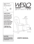
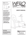
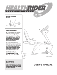
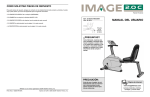
HOW TO ORDER REPLACEMENT PARTS
If you encounter any difficulties with this product, or if you need to order replacement parts, write or call the
ICON Fitness Lifestyle Ltd. office at:
ICON Fitness Lifestyle Ltd.
Greenwich House
223 North Street
Sheepscar
West Yorkshire
Leeds LS7 2AA
Model No. PFENEX37080
Serial No.
Tel: Country Code: 0345-089009
Fax: 0113-2411120
USERÕS MANUAL
Write the serial number in the
space above for future reference.
Serial
Number
Decal
Please provide the following information when calling or writing:
¥ The MODEL NUMBER of the product (PFENEX37080)
¥ The NAME of the product (PROFORM¨ REBEL Recumbent Bike and Elliptical Crosstrainer)
¥ The SERIAL NUMBER of the product (see the front cover of this manual)
¥ The KEY NUMBER and DESCRIPTION of the part(s) (see the PART LIST on page 14 of this manual).
QUESTIONS?
As a manufacturer, we are committed to providing complete
customer satisfaction. If you
have questions, or if there are
missing or damaged parts, we
will guarantee complete satisfaction through our Customer
Service Department.
Please CALL:
0345-089009
Or WRITE:
ICON Fitness Lifestyle Ltd.
Greenwich House
223 North Street
Sheepscar
West Yorkshire
Leeds LS7 2AA
Patent Pending
CAUTION
PROFORM¨ is a registered trademark of ICON Health & Fitness, Inc.
Part No. 163301 R0100A
Printed in China © 2000
Read all precautions and instructions in this manual before using
this equipment. Keep this manual for future reference.
Visit our website at
www.proform.com
new products, prizes,
fitness tips, and much more!
R0100A
2
66
68
54
54
47
21
41
61
12
50
30
61
48
33
12
52
10
9
1
39
38
71
42
81
62
67
36
17
18 65
23
74
38
14
67
30
15
29
76 80
76
75
77
44
47
78
79
78
77
30
37
5
69
70 35
46
70
4
45
30
60
51 72
84 83
13
63
16
73
51
69
28
72
71
3
8
4
6
43 28
71
WARNING: Before beginning this or any exercise program, consult your physician. This is especially important for persons over the age of 35 or persons with pre-existing health problems. Read
all instructions before using. ICON assumes no responsibility for personal injury or property
damage sustained by or through the use of this product.
83
7. Wear appropriate exercise clothing when
using the REBEL. Always wear athletic
shoes for foot protection.
13
13. The pulse sensor is not a medical device.
Various factors, including the user's movement, may affect the accuracy of heart rate
readings. The pulse sensor is intended only
as an exercise aid in determining heart rate
trends in general.
71
84
6. The REBEL should not be used by
persons weighing more than 115 kg.
57
47
54
53
12. The REBEL is intended for in-home use
only. Do not use it in any commercial, rental
or institutional setting.
5. Keep children under the age of 12 and pets
away from the REBEL at all times.
49
54
82
11. If you feel pain or dizziness while exercising, stop immediately and begin cooling
down.
4. Inspect and tighten all parts regularly.
Replace any worn parts immediately.
53
10. Keep your back straight when using the
REBEL. Do not arch your back.
2
3. Place the REBEL on a level surface, with a
mat beneath it to protect the floor or
carpet. Keep the REBEL indoors, away from
moisture and dust.
40
9. When you stop exercising, allow the pedals
to slowly come to a stop.
7 15
2. It is the responsibility of the owner to
ensure that all users of the REBEL are adequately informed of all precautions.
57
8. Always hold the handlebars when mounting,
dismounting and using the REBEL. Step
onto and off the pedal that is in the lowest
position when mounting and dismounting.
1. Read all instructions in this manual before
using the REBEL.
22
44
31
4
WARNING: To reduce the risk of serious injury, read the following important precautions before
using the PROFORM¨ REBEL Recumbent Bike and Elliptical Crosstrainer.
58
56
34 59
33
20
26 25
24
IMPORTANT PRECAUTIONS
26 25
11
24
22
55
23
4
30
29
4
19
3
65
47
10
62
9
18
39
42
32
39 64
8
4
IMPORTANT PRECAUTIONS . . . . . . . . . . . . . . . . . . . . . . . . . . . . . . . . . . . . . . . . . . . . . . . . . . . . . . . . . . . . .2
BEFORE YOU BEGIN . . . . . . . . . . . . . . . . . . . . . . . . . . . . . . . . . . . . . . . . . . . . . . . . . . . . . . . . . . . . . . . . . . .3
PART IDENTIFICATION CHART . . . . . . . . . . . . . . . . . . . . . . . . . . . . . . . . . . . . . . . . . . . . . . . . . . . . . . . . . . .4
ASSEMBLY . . . . . . . . . . . . . . . . . . . . . . . . . . . . . . . . . . . . . . . . . . . . . . . . . . . . . . . . . . . . . . . . . . . . . . . . . . .5
HOW TO USE THE PROFORM¨ REBEL . . . . . . . . . . . . . . . . . . . . . . . . . . . . . . . . . . . . . . . . . . . . . . . . . . . . .8
MAINTENANCE . . . . . . . . . . . . . . . . . . . . . . . . . . . . . . . . . . . . . . . . . . . . . . . . . . . . . . . . . . . . . . . . . . . . . . .10
CONDITIONING GUIDELINES . . . . . . . . . . . . . . . . . . . . . . . . . . . . . . . . . . . . . . . . . . . . . . . . . . . . . . . . . . . .12
PART LIST . . . . . . . . . . . . . . . . . . . . . . . . . . . . . . . . . . . . . . . . . . . . . . . . . . . . . . . . . . . . . . . . . . . . . . . . . . .14
EXPLODED DRAWING . . . . . . . . . . . . . . . . . . . . . . . . . . . . . . . . . . . . . . . . . . . . . . . . . . . . . . . . . . . . . . . . .15
HOW TO ORDER REPLACEMENT PARTS . . . . . . . . . . . . . . . . . . . . . . . . . . . . . . . . . . . . . . . . . . .Back Cover
81
EXPLODED DRAWINGÑModel No. PFENEX37080
27
TABLE OF CONTENTS
PART LISTÑMODEL No. PFENEX37080
Key No. Qty.
1
2
3
4
5
6
7
8
9
10
11
12
13
14
15
16
17
18
19
20
21
22
23
24
25
26
27
28
29
30
31
32
33
34
35
36
37
38
39
40
41
42
43
1
1
2
12
1
1
1
2
2
2
1
2
2
1
1
1
1
2
1
1
1
3
2
2
2
2
1
8
2
9
1
1
1
1
1
1
1
2
4
1
1
2
1
Description
Key No. Qty.
Base
Upright
Pedal Leg
M4 x 38mm Screw
Console
Seat Bar
Handlebar
Pedal Bolt
1/2Ó Nylon Locknut
Crank Arm
Left Side Shield
Crank Bearing
M10 x 25mm Button Head Bolt
Allen Wrench
Handlebar Wire
Seat Bar Wire
Crank Nut
5/16Ó x 3/4Ó Tap Screw
Pulley
Flywheel w/Hub
Flywheel Axle
M10 Flat Washer
M10 Nut
M6 Eyebolt
Adjustment Bracket
M6 Nut
Right Side Shield
M6 x 16mm Seat Screw
Pedal
M4 x 16mm Tapping Screw
Resistance Strap
Drive Belt
Resistance Cable w/Spring
Resistance Knob
Seat Cover
Left Toe Pedal
Rail Stabiliser
Rail Endcap
Bushing
Backrest
Small Spring
Plastic Pedal Spacer
Seat
44
45
46
47
48
49
50
51
52
53
54
55
56
57
58
59
60
61
62
63
64
65
66
67
68
69
70
71
72
73
74
75
76
77
78
79
80
81
82
83
84
#
#
2
1
1
4
1
1
1
4
1
2
6
1
1
4
1
1
2
2
2
1
1
2
2
4
1
3
2
6
2
1
1
2
4
4
4
2
2
2
1
2
2
1
1
R0100A
Description
1 1/2Ó x 2 1/2Ó Inner Cap
Console Axle
Console Spring
Stabiliser Endcap
Reed Switch/Sensor Wire
Extension Wire
Reed Switch Clip
Handlebar Screw
M4 x 16mm Flat Head Screw
Plastic Sleeve
M10 Nylon Locknut
Magnet
Clamp Bolt
1/4Ó Flat Washer
1/4Ó Nylon Locknut
Resistance Strap Hook
Console Washer
Flywheel Bearing
Crank Cover
Seat Cap
Right Toe Pedal
Crank Washer
M10 x 75mm Bolt
M10 x 68mm Bolt
Stabiliser
Console Mount Screw
Plastic Washer
M10 Washer
Grip
Detent Ring Collar
Buckle
M8 x 57mm Bolt
M8 Washer
Metal Wheel Spacer
Wheel Bearing
Pedal Wheel
M8 Nylon Locknut
Lock Pin
Upright Cap
Metal Handlebar Spacer
M16 Flat Washer
Grease Pack
UserÕs Manual
BEFORE YOU BEGIN
Congratulations for selecting the revolutionary PROFORM¨ REBEL Recumbent Bike and Elliptical
Crosstrainer. The REBEL is an incredibly smooth
exerciser that moves your feet in a natural elliptical
path, minimising the impact on your knees and ankles.
And the unique REBEL can easily be converted from
an elliptical crosstrainer to a recumbent bike, giving you
two machines in one. Welcome to a whole new world
of natural, elliptical-motion exercise from PROFORM.
tions, please call our Customer Service Department at
0345-089009. To help us assist you, please mention
the product model number and serial number when
calling. The model number is PFENEX37080. The
serial number can be found on a decal attached to the
REBEL (see the front cover of this manual).
Before reading further, please look at the drawing
below and familiarise yourself with the parts that are
labelled.
For your benefit, read this manual carefully before
you use the REBEL. If you have additional ques-
The decal shown below has been placed on the
REBEL. If the decal is missing, or if it is not legible,
please call our Customer Service Department at
0345-089009 to order a free replacement decal.
Apply the decal in the location shown.
Console
Book Holder
and Seat
Handlebar
FRONT
Backrest
Lock Knob
(on back)
Upright
Resistance Knob
Side Shield
Base
Note: Ò#Ó indicates a non-illustrated part. Specifications are subject to change without notice. See the back cover
of this manual for information about ordering replacement parts.
Pedal
BACK
14
Toe Pedal
Pedal Leg
3
RIGHT SIDE
PART IDENTIFICATION CHART
Use the chart below to identify the small parts used in
assembly. The number in parenthesis below each part
is the key number of the part, from the PART LIST on
page 14. The number after the dash indicates the
EXERCISE FREQUENCY
quantity needed for assembly. Note: Some small
parts may have been pre-attached for shipping. If
a part is not in the parts bag, check to see if it has
been pre-attached.
To maintain or improve your condition, plan three
workouts each week, with at least one day of rest
between workouts. After a few months of regular
exercise, you may complete up to five workouts each
week, if desired. Find the best time of day for your
workouts, and then stick with it.
SUGGESTED STRETCHES
1
The correct form for several basic stretches is shown at the
right. Move slowly as you stretchÑnever bounce.
1. Toe Touch Stretch
M10 Nylon Locknut (54)Ñ6
1/2" Nylon Locknut (9)Ñ2
M10 Washer (71)Ñ6
Stand with your knees bent slightly and slowly bend forward
from your hips. Allow your back and shoulders to relax as you
reach down toward your toes as far as possible. Hold for 15
counts, then relax. Repeat 3 times. Stretches: Hamstrings,
back of knees and back.
2
2. Hamstring Stretch
Metal Handlebar Spacer (83)Ð2
Sit with one leg extended. Bring the sole of the opposite foot
toward you and rest it against the inner thigh of your extended
leg. Reach toward your toes as far as possible. Hold for 15
counts, then relax. Repeat 3 times for each leg. Stretches:
Hamstrings, lower back and groin.
M16 Flat Washer (84)Ñ2
Plastic Pedal Spacer (42)Ñ2
Plastic Sleeve (53)Ñ2
Pedal Bolt (8)Ñ2
3
3. Calf/Achilles Stretch
With one leg in front of the other, reach forward and place
your hands against a wall. Keep your back leg straight and
your back foot flat on the floor. Bend your front leg, lean forward and move your hips toward the wall. Hold for 15 counts,
then relax. Repeat 3 times for each leg. To cause further
stretching of the achilles tendons, bend your back leg as well.
Stretches: Calves, achilles tendons and ankles.
4
4. Quadriceps Stretch
M4 x 38mm Screw (4)Ñ2
M10 x 68mm Bolt (67)Ð4
With one hand against a wall for balance, reach back and
grasp one foot with your other hand. Bring your heel as close
to your buttocks as possible. Hold for 15 counts, then relax.
Repeat 3 times for each leg. Stretches: Quadriceps and hip
muscles.
M4 x 16mm Tapping Screw (30)Ñ8
5. Inner Thigh Stretch
M10 x 75mm Bolt (66)Ð2
Sit with the soles of your feet together and your knees outward. Pull your feet toward your groin area as far as possible.
Hold for 15 counts, then relax. Repeat 3 times. Stretches:
Quadriceps and hip muscles.
M6 x 16mm Seat Screw (28)Ð8
Console Mount Screw (69)Ð1
Handlebar Screw (51)Ð4
M10 x 25mm Button Head Bolt (13)Ð2
4
13
5
CONDITIONING GUIDELINES
rate should be maintained at a level between 70% and
85% of your maximum heart rate as you exercise. This
is known as your training zone. You can find your training zone in the table at the bottom of this page.
Training zones are listed according to age and physical condition.
WARNING: Before beginning this or any exercise program, consult your physician. This is
especially important for individuals over the
age of 35 or individuals with pre-existing health
problems.
Burning Fat
WARNING: The pulse sensor is not a medical
device. Various factors may affect the accuracy
of heart rate readings. The pulse sensor is
intended only as an exercise aid in determining
heart rate trends in general.
To burn fat effectively, you must exercise at the proper
intensity level for a sustained period of time. During
the first few minutes of exercise, your body uses easily accessible carbohydrate calories for energy. Only
after the first few minutes does your body begin to use
stored fat calories for energy. If your goal is to burn
fat, keep your heart rate in the lower end of your training zone.
WHY EXERCISE?
Aerobic Exercise
EXERCISE INTENSITY
Whether your goal is to burn fat or to strengthen your
cardiovascular system, the key to achieving the
desired results is to exercise with the proper intensity.
The proper intensity level can be found by using your
heart rate as a guide. For effective exercise, your heart
UNCONDITIONED CONDITIONED
138Ð167
133Ð162
25
136Ð166
132Ð160
30
135Ð164
130Ð158
35
134Ð162
129Ð156
40
132Ð161
127Ð155
45
131Ð159
125Ð153
50
129Ð156
124Ð150
55
127Ð155
122Ð149
60
126Ð153
121Ð147
65
125Ð151
119Ð145
70
123Ð150
118Ð144
75
122Ð147
117Ð142
80
120Ð146
115Ð140
85
118Ð144
114Ð139
Assembly requires a phillips screwdriver
, two adjustable spanners
rubber mallet
(none of these is included).
1. Hold the Stabiliser (68) against the saddle on the rear
of the Base (1). Attach the Stabiliser with two M10 x
75mm Bolts (66) and two M10 Nylon Locknuts (54).
and a
54
1
1
54
68
If your goal is to strengthen your cardiovascular system, your exercise must be Òaerobic.Ó Aerobic exercise
is activity that requires large amounts of oxygen for
prolonged periods of time. This increases the demand
on the heart to pump blood to the muscles, and on the
lungs to oxygenate the blood. For effective aerobic
exercise, keep your heart rate in the higher end of
your training zone.
HOW TO MEASURE YOUR HEART RATE
2. Slide the Rail Stabiliser (37) onto the Base (1), so the
ÒUÓ-channel on the Stabiliser fits into the Base. Make
sure that the Reed Switch Wire (48) is extending
from the hole that will be formed as the two parts
slide together. Make sure you donÕt damage the
Reed Switch Wire when the two parts meet.
2
37
ÒUÓ-channel
48
Insert two M10 x 68mm Bolts (67) with two M10
Washers (71) up through the Base (1) and the Rail
Stabiliser (37). Note: It may be easier to insert the
Bolts if the unit is tipped on its side.
71
To measure your heart rate, follow the procedure
described on page 10.
TRAINING ZONE (BEATS/MIN.)
20
Assembly requires two persons. Place all parts of the PROFORM¨ REBEL in a cleared area and remove the
packing materials. Do not dispose of the packing materials until assembly is completed.
66
Exercise has proven essential for good health and
well-being. Participation in a well-rounded exercise
program helps to develop a stronger and more efficient heart, improved respiratory function, increased
stamina, better weight management, increased ability
to handle stress, and greater self-esteem.
AGE
ASSEMBLY
WORKOUT GUIDELINES
A proper workout includes the following three important
parts:
A warm-up, consisting of 5 to 10 minutes of stretching
and light exercise. A proper warm-up increases the
body temperature, heart rate, and circulation in preparation for exercise.
A cardiovascular exercise period, including 20 to
30 minutes of exercise with your heart rate in your
training zone.
1
67
3. While one person holds the Upright (2), connect the
Extension Wire (49) to the Reed Switch Wire (48)
extending from the Base (1). Insert any excess wire
into the Upright or the Base.
3
54
54
Slide the Upright (2) onto the four M10 x 68mm Bolts
(67). Make sure that the wires do not get pinched
as you slide the Upright into place.
2
49
Hand tighten an M10 Nylon Locknut (54) onto each
M10 x 68mm Bolt (67). Tip the unit on its side and use
two spanners to tighten the Nylon Locknuts fully.
48
1
A cool-down, with 5 to 10 minutes of stretching.
Thorough stretching helps to offset problems caused
when you stop exercising suddenly. Stretching after
exercise is also very effective for increasing flexibility.
67
12
5
4. Connect the Seat Bar Wire (16) to the Handlebar Wire
(15).
4
7
Slide the Handlebar (7) onto the Seat Bar (6). Attach
the Handlebar with the four Handlebar Screws (51).
Make sure that the Handlebar Screws do not damage
the wires.
Pull both Grips (72) toward the Handlebar (7) until they
cover the Handlebar Screws (51).
72
51
15
16
6
51
72
5. Remove the Console Mount Screw (69) and slide the
Detent Ring Collar (73) off the shaft of the Console (5).
5
69
Console
Wire
Insert the console wire through the indicated hole in
the Seat Bar (6).
6
16
Using the included grease pack, lubricate the shaft of
the Console (5). Insert the shaft into the indicated hole
in the Seat Bar (6).
Slide the Detent Ring Collar (73) onto the console
shaft and line up the hole in the Detent Ring Collar
with the hole in the shaft. Secure the Console (5) with
the Console Mount Screw (69) (see the inset drawing).
Lubricate
6
Attach the Seat Cover (35) to the Seat (43), using two
M4 x 38mm Screws (4) along the rear edge and an M4
x 16mm Tapping Screw (30) on each side.
43
6
28
4
28
6
If the Drive Belt (32) slips as you exercise, the Drive
Belt should be adjusted. To adjust the Drive Belt, both
Side Shields (11 and 27, not shown) must first be
removed as described on page 10.
Next, locate the
Reed Switch
(48). Turn the
Pulley (19) until
55
the Magnet (55)
is aligned with
51
the Reed Switch.
48
Loosen, but do
19
not remove, the
M4 x 16mm
Tapping Screw
(30, shown
removed for clarity). Slide the Reed Switch slightly
toward or away from the Magnet. Make sure that the
Magnet will not hit the Reed Switch. Retighten the
Screw. Turn the Pulley (19) for a moment. Repeat until
the console displays correct feedback. When the Reed
Switch is correctly adjusted, re-attach the left side
shield.
Next, loosen the
two M10 Nuts
20
(23) (there is
32
one on each
26
side of the
Flywheel [20]).
To tighten the
Drive Belt (32),
23
turn the two M6
Nuts (26) clockwise; to loosen
the Drive Belt,
turn the M6 Nuts
counterclockwise. Make sure that the Flywheel is
straight and retighten the M10 Nuts (23). When the
Drive Belt is properly adjusted, re-attach the side
shields.
HOW TO ADJUST THE RESISTANCE STRAP
If the Crank Arms (10) become loose, they should be
tightened in order to prevent excessive wear. To tighten the Crank Arms, the Left Side Shield (11, not
shown) must first be removed as described on page 10.
HOW TO TIGHTEN THE CRANK
Next, loosen the
Crank Nut (17)
on the left
Slotted Crank Nut
Crank Arm (10).
Place the end
of a standard
10
screwdriver in
one of the slots
17
in the Slotted
Crank Nut.
Lightly tap the
screwdriver with
a hammer to turn the Slotted Crank Nut counterclockwise until the arms are no longer loose. Do not overtighten the Slotted Crank Nut. When the Slotted
Crank Nut is properly tightened, retighten the Crank
Nut and re-attach the left side shield.
Turn the resistance knob to the
20
lowest setting (see
74
HOW TO ADJUST
THE RESISTANCE OF THE
PEDALS on page
31
9). Open the
Buckle (74) and
pull the end of the
Resistance Strap
(31) slightly downward. Close the
Buckle and turn the Flywheel (20) to make sure that
there is not too much resistance. When the
Resistance Strap is properly adjusted, re-attach the
left side shield.
30
4
30
If the console does not display correct feedback, the
reed switch should be adjusted. To adjust the reed
switch, the Left Side Shield (11, not shown) must first
be removed as described on page 10.
If the pedals do not have enough resistance, even
when the resistance knob is turned to the maximum
setting, the Resistance Strap (31) may need to be
adjusted. To adjust the Resistance Strap, the Left Side
Shield (11, not shown) must first be removed, as
described on page 10.
73
5
6. Attach the Seat (43) to the indicated brackets on the
Seat Bar (6) with four M6 x 16mm Seat Screws (28).
HOW TO ADJUST THE DRIVE BELT
69
73
Plug the console wire into the Seat Bar Wire (16).
HOW TO ADJUST THE REED SWITCH
35
11
which mode is
currently displayed. Note: If
a different
mode is selected, you can
select the scan
mode again by
repeatedly
pressing the mode button.
will appear in the display
and your pulse will be
shown. Hold your thumb
on the sensor for another
15 seconds for the most
accurate reading. If the
displayed pulse appears
to be too high or too low,
or if your pulse is not displayed, lift your thumb off
the sensor and allow the
display to reset. Press
down again on the sensor as described above.
Mode Indicators
Speed, time, distance, fat calorie or calorie
modeÑTo select one of these modes for continuous display, press the mode button repeatedly. The
mode indicators will show which mode is selected.
(Make sure that the scan mode is not selected.)
Make sure that your thumb is positioned as shown,
and that you are applying the proper amount of
pressure to the pulse sensor. Try the sensor several
times until you become familiar with it.
3. To measure your pulse, stop pedalling and place
your thumb on the pulse sensor as shown. The
pulse sensor is pressure-activatedÑfully press
down the pulse sensor. Do not press too hard, or
the circulation in your thumb will be restricted,
and your pulse will not be detected. Next, slightly
raise your thumb until the heart-shaped indicator in
the LCD display flashes steadily. Hold your thumb
at this level. After 5 to 10 seconds, three dashes
4. To reset the display, press the on/reset button.
5. The console has an Òauto-offÓ feature. If the
pedals are not moved and the console buttons
are not pressed for four minutes, the power will
turn off automatically to conserve the batteries.
7. Note: The assistance of another person is recommended for this step.
7
7
While another person holds the Handlebar (7) in the
position shown, connect the Handlebar Wire (15) to
the Extension Wire (49) extending from the Upright (2).
Brackets
15
13
71
2
Slide a Plastic Sleeve (53) onto each of the indicated
shafts on the Upright (2).
49
84
83
Slide an M10 Washer (71) onto each of the M10 x
25mm Button Head Bolts (13). Next, insert the Bolts
through the brackets on the Handlebar (7) and then
slide an M16 Flat Washer (84) and a Metal Handlebar
Spacer (83) onto each Bolt. Insert the Bolts into the
shafts on the Upright (2) and tighten them with the
included allen wrench. Be careful not to overtighten
the Bolts; the Handlebar must pivot easily.
53
71
13
84 83 53
Shaft
8
8. Attach the Backrest (40) to the indicated brackets on
the Upright (2) with four M6 x 16mm Seat Screws (28).
40
28
2
28
MAINTENANCE
unscrew the three M4 x 38mm Screws (4) from the
lower edge of the Right Side Shield. Remove the 1/2Ó
Nylon Locknut (9), Pedal Bolt (8) and Plastic pedal
Spacer (42) from the right Pedal Leg (not shown).
Gently pull the Right Side Shield over the Crank Arm.
CONSOLE TROUBLE-SHOOTING
If the console does not function properly, the batteries
should be replaced. To replace the batteries, see
assembly step 10 on page 8. In addition, make sure
that the console wire is connected to the seat bar
wire. See assembly step 5 on page 6.
9. Identify the left Pedal Leg (3) by looking at the
Lock Pin (81) on the pre-assembled Left Toe Pedal
(36). The Lock Pin must be on the outside when
the Pedal Leg is mounted.
9
Attach a Pedal (29) to the left Pedal Leg (3) with three
M4 x 16mm Tapping Screws (30).
11
HOW TO REMOVE THE SIDE SHIELDS
For all of the following steps, one or both Side Shields
(11 and 27) must be removed.
4
27
4
4
42
To remove the Left Side Shield (11), remove the 1/2Ó
Nylon Locknut (9) and remove the Pedal Bolt (8) and
the Plastic Pedal Spacer (42) from the Pedal Leg (3).
Next, remove the seven M4 x 38mm Screws (4) from
the Left Side Shield. Gently pull the Left Side Shield
out and to the side, so the Crank Arm (10) fits through
the hole in the Left Side Shield.
3
9
10
Lubricate a Pedal Bolt (8) with the included grease
pack and slide it through the two pre-assembled
Bushings (39). Slide a Plastic Pedal Spacer (42) onto
the Pedal Bolt (8) and slide the Bolt into the hole in the
left Crank Arm (10). Tighten a 1/2Ó Nylon Locknut (9)
onto the Pedal Bolt (8).
Repeat this procedure for the right Pedal Leg (not
shown).
36
29
30
81
39
4
42
10
8
8
4
To remove the Right Side Shield (27), first remove the
Left Side Shield (11) as described above. Then,
10
9
3
7
Lubricate
10. The Console (5) requires two 1,5V batteries (not
included). Alkaline batteries are recommended.
10
To install batteries, first slide up the battery cover and
carefully remove the battery clip from the Console (5).
Insert two batteries into the battery clip as shown.
Make sure that the negative ends of the batteries
(marked ÒÐÓ) are touching the springs in the
battery clip. Replace the battery clip and close the
battery cover.
Battery
Cover
Battery
Clip
To dismount the REBEL, allow the pedals to slowly
come to a stop. CAUTION: The REBEL does not
have a freewheel; the pedals will continue to
move until the flywheel stops. When the pedals are
stationary, step off the highest pedal first. Then, step
off the lowest pedal.
Thumb
Pulse
Sensor
HOW TO ADJUST THE TOE PEDALS
5
To adjust the Right Toe Pedal (64), pull out the Lock
Pin (81). Slide the Toe Pedal forwards or backwards
to the desired position. Push the Lock Pin through the
holes in the Toe Pedal and the adjustment holes in
the Pedal Leg (3). Adjust the Left Toe Pedal (36, not
shown) in the same manner.
LCD
Display
11. Make sure that all parts of the REBEL are properly tightened. To protect the floor or carpet from damage,
place a mat under the REBEL. Note: There may be some hardware left over after assembly is completed.
SPEEDÑThis mode displays your pedalling speed, in
miles per hour.
HOW TO USE THE PROFORM¨ REBEL
HOW TO SWITCH BETWEEN RECUMBENT BIKE
AND ELLIPTICAL CROSSTRAINER
TIMEÑThis mode displays the elapsed time. Note:
When you stop exercising, the time mode will pause.
To switch from elliptical crosstrainer to recumbent
bike, loosen the lock knob (not visible). Fold the Seat
(43) down and turn the Console (5) so it is visible
when you are sitting on the Seat.
To switch from recumbent bike to elliptical crosstrainer, lift the Seat (43) as far as it will go. Tighten the
lock knob (not visible) into the Upright (2). Note:
Tighten the lock knob fully. Push the Console (5) in
to disengage the lock, and then turn it so the display
is visible when you are standing on the pedals.
3
DISTANCEÑThis mode displays the total distance
you have pedalled, in miles.
64
81
FAT CALORIEÑThis mode displays the approximate
number of fat calories you have burned (see BURNING FAT on page 12).
HOW TO EXERCISE ON THE REBEL WHEN IT IS
SET UP AS AN ELLIPTICAL CROSSTRAINER
To mount the REBEL in the crosstrainer mode, hold
the handlebars and step onto the pedal that is in the
lowest position. Next, step onto the other pedal. Push
the pedals until they begin to move with a continuous
motion. Note: The crank can turn in either direction. To get the full impact of the elliptical motion,
it is recommended that you turn the crank in the
direction shown by the arrow below; however, to
give variety to your exercise, you may choose to
turn the crank in the opposite direction.
Lock Knob
HOW TO ADJUST THE RESISTANCE OF
THE PEDALS
As you exercise,
you can adjust the
resistance of the
pedals with the
resistance knob.
To increase the
resistance, turn the
knob clockwise; to
decrease the resistance, turn the
knob counterclockwise.
CALORIEÑThis mode displays the approximate number of Calories you have burned.
Resistance Knob
SCANÑThis mode displays the speed, time, distance,
fat calorie and calorie modes, for 5 seconds each, in
a repeating cycle.
PULSEÑThis mode displays your heart rate when the
pulse sensor is used.
HOW TO OPERATE THE CONSOLE
If there is a thin sheet of clear plastic on the face of
the console, remove it.
DESCRIPTION OF THE CONSOLE
5
Pedal
43
2
Crank
8
1. To turn on the power, press the on/reset button or
simply begin pedalling. When the power is turned
on, the entire display will appear for two seconds.
The console will then be ready for operation.
The console is designed to help you get the most
from your workouts. As you exercise, you can watch
your progress as the display provides continuous
exercise feedback. You can even measure your heart
rate using the built-in pulse sensor. The modes of the
display are described below. Note: Before the console can be operated, two 1,5V batteries must be
installed (see assembly step 10 on page 8).
2. Select one of the modes:
Scan modeÑWhen the power is turned on, the
scan mode will automatically be selected. One
mode indicator will show that the scan mode is
selected, and a flashing mode indicator will show
9