1
APPLICATION NOTE
RX Family
R01AN1685EJ0310
Rev. 3.10
Dec. 1, 2015
Board Support Package Module Using Firmware Integration Technology
Introduction
The foundation of any project that uses FIT modules is the Renesas Board Support Package (r_bsp). The r_bsp is easily
configurable and provides all the code needed to get the MCU from reset to main(). The document covers conventions
of the r_bsp so that users will know how to use it, configure it, and create a BSP for their own board.
Target Device
The following is a list of devices that are currently supported:
•
RX110, RX111, RX113 Groups
•
RX130 Group
•
RX210, RX21A Groups
•
RX220 Group
•
RX231 Group
•
RX23T Group
•
RX610 Group
•
RX62N, RX62T, RX62G Groups
•
RX630, RX631, RX63N, RX63T Groups
•
RX64M Group
•
RX71M Group
When using this application note with other Renesas MCUs, careful evaluation is recommended after making
modifications to comply with the alternate MCU.
Related Documents
Firmware Integration Technology User’s Manual (R01AN1833EU)
•
Contents
1.
Overview ........................................................................................................................................... 2
2.
Features ............................................................................................................................................ 4
3.
Configuration ................................................................................................................................... 10
4.
API Information ............................................................................................................................... 18
5.
API Functions .................................................................................................................................. 23
6.
Project Setup ................................................................................................................................... 42
7.
Adding r_bsp manually.................................................................................................................... 50
Website and Support ............................................................................................................................... 61
R01AN1685EJ0310 Rev. 3.10
Dec. 1, 2015
Page 1 of 61
RX Family Board Support Package Module Using Firmware Integration Technology
1. Overview
Before running the user application there are a series of operations that must be performed to get the MCU set up
properly. These operations, and the number of operations, will vary depending on the MCU being used. Common
examples include: setting up stack(s), initializing memory, configuring system clocks, and setting up port pins. No
matter the application, these steps need to be followed. To make this process easier the Renesas Board Support Package,
abbreviated as r_bsp, is provided.
At the lowest level the r_bsp provides everything needed to get the user’s MCU from reset to the start of their
application’s main() function. The r_bsp also provides common functionality that is needed by many applications.
Examples of this include callbacks for exceptions and functions to enable or disable interrupts.
While every application will need to address the same steps after reset, this does not mean that the settings will be the
same. Depending on the application, stack sizes will vary and which clock is used will change. All r_bsp configuration
options are contained in one header file for easy access.
Many customers start development on a Renesas development board and then transition to their own custom boards.
When users move to their own custom hardware it is highly recommended they create a new BSP inside of the r_bsp.
By following the same standards and rules that are used for the provided BSPs the user can get an early start on
development knowing that their application code will move to their target board very easily. Details on how users can
create their own BSPs are provided in this document.
1.1
Terminology
Term
Meaning
Platform
The user’s development board. Used interchangeably with ‘board’.
BSP
Short for Board Support Package. BSP’s usually have source files related to a specific
board.
Callback Function
This term refers to a function that is called when an event occurs. For example, the bus
error interrupt handler is implemented in the r_bsp. The user will likely want to know
when a bus error occurs. To alert the user, a callback function can be supplied to the
r_bsp. When a bus error occurs the r_bsp will jump to the provided callback function
and the user can handle the error. Interrupt callback functions should be kept short and
be handled carefully because when they are called the MCU will still be inside of an
interrupt and therefore will be delaying any pending interrupts.
R01AN1685EJ0310 Rev. 3.10
Dec. 1, 2015
Page 2 of 61
RX Family Board Support Package Module Using Firmware Integration Technology
1.2
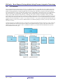
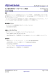
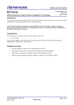
File Structure
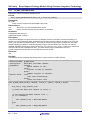
The r_bsp file structure is shown below in Figure 1-1. Underneath the root r_bsp folder there are 3 folders and 2 files.
The first folder is named doc and contains r_bsp documentation. The second folder is the board folder which has one
folder per supported board. In each board folder the user will find source files that are specific to that board. There is
also a folder named user that is provided. This folder is merely a placeholder to remind users that it is recommended for
them to create their own board folder. The third folder is the mcu folder which has one folder per supported MCU.
There is also a folder named all in this directory containing source that is common to all MCUs in the r_bsp. While
board folders have source files specific to a board, mcu folders contain source that is shared between MCUs in the same
MCU Group. This means that if the user has two distinct boards that both use a version of the RX63N then each board
will have its own board folder (i.e. board >> my_board_1 & board >> my_board_2) but both will share the same mcu
folder (i.e. mcu >> rx63n). Even if the two RX63N MCUs have different packages or memory sizes they will still share
the same mcu folder.
The file platform.h is provided for the user to choose their current development platform. platform.h, in turn, selects all
the proper header files from the board and mcu folders to be included in the user’s project. This is discussed in more
detail in later sections. The readme.txt file is a standard text file that is provided with all FIT Modules that provides
brief information about the r_bsp.
Figure 1-1 : r_bsp File Structure
R01AN1685EJ0310 Rev. 3.10
Dec. 1, 2015
Page 3 of 61
RX Family Board Support Package Module Using Firmware Integration Technology
2. Features
This section will go into more detail on the features provided by the r_bsp.
2.1
MCU Information
One of the main benefits of the r_bsp is that the user defines their global system settings only once, in a single place in
the project. This information is defined in the r_bsp and then used by FIT Modules and user code. FIT Modules can use
this information to automatically configure their code for the user’s system configuration. If the r_bsp did not provide
this information then the user would have to specify system information to each FIT Module separately.
Configuring the r_bsp is discussed in Section 3. The r_bsp uses this configuration information to set macro definitions
in mcu_info.h. Each MCU may have different macros in mcu_info.h, but below are some common examples.
Define
Meaning
BSP_MCU_SERIES_<MCU_SERIES>
Which MCU Series this MCU belongs to. Example:
BSP_MCU_SERIES_RX600 would be defined if the MCU was an
RX62N, RX62T, RX630, RX63N, etc.
BSP_MCU_<MCU_GROUP>
Which MCU Group this MCU belongs to. Example:
BSP_MCU_RX111 would be defined if the MCU was an RX111.
BSP_PACKAGE_<PACKAGE_TYPE>
The package of the MCU. Example: BSP_PACKAGE_LQFP100
would be defined for a 100-pin LQFP package MCU.
BSP_PACKAGE_PINS
How many pins this MCU has.
BSP_ROM_SIZE_BYTES
The size of the user application ROM space in bytes.
BSP_RAM_SIZE_BYTES
The size of the RAM available to the user in bytes.
BSP_DATA_FLASH_SIZE_BYTES
BSP_<CLOCK>_HZ
The size of the data flash area in bytes.
There will be one of these macros for each clock on the MCU.
Each macro will define that clock’s frequency in Hertz. Examples:
BSP_LOCO_HZ defines the LOCO frequency in Hz.
BSP_ICLK_HZ defines the CPU clock in Hz.
BSP_PCLKB_HZ defines the Peripheral Clock B in Hz.
BSP_MCU_IPL_MAX
The maximum interrupt priority level for the MCU.
BSP_MCU_IPL_MIN
The minimum interrupt priority level for the MCU.
FIT_NO_FUNC
and
FIT_NO_PTR
R01AN1685EJ0310 Rev. 3.10
Dec. 1, 2015
These macros can be used as arguments in function calls to specify
that the nothing is being supplied for an argument. For example, if
a function takes an optional argument for a callback function then
FIT_NO_FUNC could be used if the user did not wish to supply a
callback function. These macros are defined to point to reserved
address space. This is done so that if the argument is used
improperly it is easier to catch. The reason for this is that if the
MCU attempts to access reserved space then a bus error will occur
and the user will know immediately. If NULL was used instead
then a bus error would not occur because NULL is typically
defined as 0 which is a valid RAM location on the RX.
Page 4 of 61
RX Family Board Support Package Module Using Firmware Integration Technology
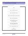
2.2
Initialization
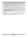
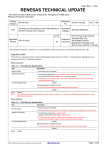
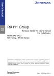
The PowerON_Reset_PC() function in resetprg.c is set as the reset vector for the MCU. This function performs a
number of chip initialization actions to get the MCU ready to jump to the user’s application. The flowchart below
details the operations this function performs.
Figure 2-1: PowerON_Reset_PC() Flowchart
R01AN1685EJ0310 Rev. 3.10
Dec. 1, 2015
Page 5 of 61
RX Family Board Support Package Module Using Firmware Integration Technology
2.3
Global Interrupts
Interrupts on RX MCUs are disabled out of reset. The PowerON_Reset_PC() function will enable interrupts before the
user’s application is called (see Section 2.2).
RX devices have two vector tables: a relocatable vector table and a fixed vector table. As the names suggest the
relocatable vector table can be anywhere in memory and the fixed vector table is at a static location at the top of the
memory map.
The relocatable vector table holds peripheral interrupt vectors and is pointed to by the INTB register. This register is
initialized after reset in the PowerON_Reset_PC() function. The vectors in the relocatable vector table are inserted by
the RX toolchain. The RX toolchain knows about the user’s interrupt vectors by the use of the ‘#pragma interrupt’
directives in the user’s code.
The fixed vector table holds exception vectors, the reset vector, as well as some flash-based option registers. The fixed
vector table is defined in vecttbl.c along with default interrupt handlers for all exceptions, the NMI interrupt, bus errors,
and undefined interrupts. The user has the option of dynamically setting callbacks (see Section 2.4) for all of these
vectors using the functionality found in mcu_interrupts.c. The vecttbl.c file also takes care of setting up the User Boot
reset vector when applicable.
All vectors in the fixed vector table are handled in vecttbl.c. All vectors in the relocatable vector table are not handled
because the user will define these vectors and each application will be different. This means that in every application
there will be unfilled vectors that should be taken care of in case that interrupt is triggered by accident. Many linkers
support the filling of unused vectors with a static function. The undefined_interrupt_source_isr() function in vecttbl.c is
provided for this purpose and the user is encouraged to setup the linker to fill in unused vectors with this function’s
address.
2.4
Interrupt Callbacks
The r_bsp provides several API functions (see Section 5.13 through 5.15) which allow the user to be alerted when
certain interrupts are triggered. This works by the user selecting the interrupt and then providing a callback function.
When the interrupt is triggered the r_bsp will call the supplied callback function.
Currently, the user can choose to register callbacks for all exception interrupts in the fixed vector table, the bus error
interrupt, and the undefined interrupt. After the user callback function has been executed, the r_bsp interrupt handler
will clear any interrupt flags as needed.
2.5
Non-Existent Port Pins
Within a MCU Group there can be many different packages with varying number of pins. For packages that have less
pins than the maximum (e.g. 64 pin package in a MCU group that goes up to 144 pins), the non-bonded out pins can be
initialized to lower power consumption. Based on the settings in r_bsp_config.h the r_bsp will automatically initialize
these non-bonded out pins during the MCU initialization procedure. This feature is implemented in the mcu_init.c
function and is called by the hardware_setup() function.
2.6
Clock Setup
All system clocks are setup during r_bsp initialization. The clocks are configured based upon the user’s settings in the
r_bsp_config.h file (see Section 3.2.6). Clock configuration is performed prior to initializing the C runtime environment.
This is done to quicken this process since some RX MCUs startup on a relatively slow clock (i.e. RX63x starts on
125kHz Low-Speed On-Chip Oscillator). When selecting a clock the code in the r_bsp will implement the required
delays to allow the selected clock to stabilize.
Some RX MCUs are necessary to set a cycle of waiting for access to code flash memory and RAM. A cycle of waiting
for access is set by the MEMWAIT or ROMWT register. Setting value of the MEMWAIT and ROMWT register
depends on the system clocks and operating power consumption control modes.Please check the restrictions on setting
of the MEMWAIT and ROMWT register in the user's manual.
2.7
STDIO & Debug Console
When enabled (see Section 3.2.3), the STDIO library is initialized as part of the MCU initialization procedure. The
r_bsp code is setup to send STDIO output to the debug console that can be viewed in HEW or e2studio. The source file
lowlvl.c is responsible for sending and receiving bytes for STDIO functions and as previously stated is setup by default
to use the debug console. If desired the user may redirect the stdio charget() and/or charput() functions to their own
R01AN1685EJ0310 Rev. 3.10
Dec. 1, 2015
Page 6 of 61
RX Family Board Support Package Module Using Firmware Integration Technology
respective functions by modifying r_bsp_config.h and enabling BSP_CFG_USER_CHARGET_ENABLED and/or
BSP_CFG_USER_CHARPUT_ENABLED, and providing and replacing the my_sw_charget_function and/or
my_sw_charput_function function names with the names of their own functions.
2.8
Stacks & Heap
RX MCUs have two stacks that can be used: the User stack and the Interrupt stack. When both stacks are used the User
stack will be used during normal execution flow and the Interrupt stack will be used during interrupt handling. Having 2
stacks can make it easier to figure out how much stack space to allocate since the user does not have to worry about
always having enough room on the User stack for if-and-when an interrupt occurs. Some users will not want 2 stacks
though because it is not needed in all applications and can lead to wasted RAM (i.e. space in between stacks that is not
used). If only 1 stack is used then it will always be the Interrupt stack.
The User and Interrupt stacks and the heap are all setup and initialized after reset inside of the r_bsp code. The sizes of
the stacks and heap, and whether 1 or 2 stacks are used, is configured in r_bsp_config.h (see Section 3.2.2). The user
also has the option of disabling the heap if desired.
2.9
CPU Mode
Out of reset, RX MCUs operate in Supervisor CPU Mode. In Supervisor Mode all CPU resources and instructions are
available. The user has the option (see Section 3.2.4) of transitioning to User Mode before the r_bsp code jumps to
main(). In User Mode there are restrictions to any instruction capable of writing to:
•
•
•
•
•
•
Some bits (bits IPL[3:0], PM, U, and I) in the processor status word (PSW)
Interrupt stack pointer (ISP)
Interrupt table register (INTB)
Backup PSW (BPSW)
Backup PC (BPC)
Fast interrupt vector register (FINTV)
If the MCU executes one of these instructions while in User Mode, an exception will trigger. If the user has a callback
setup (see Section 2.4) then they will be alerted by a callback function of the exception.
2.10
ID Code
RX MCUs have a 16-byte ID Code in ROM that protects the MCU’s memory from being read through a debugger, or
in serial boot mode, in an attempt to extract the firmware from the device. The ID Code resides in the fixed vector table
and can easily be set in r_bsp_config.h (see Section 0). For more information on available ID Code options please
reference the ID Code subsection in the ‘Flash Memory’ or ‘ROM’ section of your MCU’s hardware manual.
2.11
Parallel Programmer Protection
Similar to the ID Code, RX MCUs also have a 4-byte code in ROM that can protect access to the MCU’s memory from
parallel programmers. The user has the option of allowing reads and write, only allowing writes, and prohibiting all
access. See Section 0 for information on how to enable this feature.
R01AN1685EJ0310 Rev. 3.10
Dec. 1, 2015
Page 7 of 61
RX Family Board Support Package Module Using Firmware Integration Technology
2.12
Endian
RX MCUs have the option of operating in big or little endian mode. Which mode is chosen is decided in different ways
depending on which MCU is being used. RX610 and RX62x MCUs have a pin where the level decides. RX100, RX200,
RX63x, RX64x, and RX700 MCUs have a register in ROM that decides the endian that will be used. For devices with
the register in ROM, the r_bsp detects the endian selected in the toolchain and will use that to appropriately set the
register. The r_bsp currently detects endian from the following toolchains:
• Renesas RXC
• IAR
• KPIT GNU
2.13
Option Function Select Registers
Starting with RX63x, RX200, and RX100 MCUs, there are registers stored in ROM called Option Function Select
registers. These registers are used to enable certain MCU features at reset instead of having to enable them in the user’s
code. Examples include the ability to enable low voltage monitoring, start the HOCO oscillating, and to configure and
start the IWDT.
The user can input the values to be used for these registers in r_bsp_config.h (see Section 0).
2.14
Trusted Memory
For both the RX64M and the RX71M there are two additional Option Function registers devoted to ‘Trusted Memory”.
This feature protects against illicit reading of blocks 8 and 9 in the code flash memory, and is disabled by default.
It may be enabled at startup by setting the BSP_CFG_TRUSTED_MODE_FUNCTION value, defined in
r_bsp_config.h to 0xF8FFFFFF. Only 0xF8FFFFFF and 0xFFFFFFFF are valid settings.
2.15
Board-Specific Defines
Each board folder has a board-specific header file which defines things such as which pins are used for LEDs, switches,
and SPI slave selects. The name of the file is the name of the board with ‘.h’ appended. For example, the file for the
RSKRX111 is named rskrx111.h.
2.16
System Wide Parameter Checking
By default FIT modules will check input parameters to be valid. This is helpful during development but some users
will want to disable this for production code. The reason for this would be to save execution time and code space. In
r_bsp_config.h there is an option to globally enable or disable parameter checking. Local modules will use this value by
default but can select to override the value locally if desired. To configure this option see Section 3.2.9.
R01AN1685EJ0310 Rev. 3.10
Dec. 1, 2015
Page 8 of 61
RX Family Board Support Package Module Using Firmware Integration Technology
2.17
Atomic Locking
The r_bsp provides API functions to implement atomic locking. These locks can be used to protect critical areas of code
as a RTOS semaphore or mutex normally would. Care should be taken when using these locks though since they do not
offer the advanced features one would expect from a modern RTOS. If used incorrectly then the locks could cause a
deadlock in the user’s system.
In each mcu folder the user will find a file named mcu_locks.h. This contains an enum named mcu_lock_t which has
one lock per peripheral, and peripheral channel, on the MCU. These locks can be used to mark that a peripheral has
been reserved. This could be used if the user wanted to use a FIT module to control three channels of a peripheral and
their own custom code for one channel. By reserving the lock for the channel they need they have removed that channel
from being used by the FIT Module. These locks can also be used if the user has more than one FIT module for the
same peripheral. For example, if the user had one FIT module for using the SCI in asynchronous mode and another for
using the SCI in I2C mode then these locks will prevent these two modules from trying to use the same SCI channel.
There are 4 locking API functions provided that are detailed in Section 5. The only difference between the hardware
and software locking functions is that the hardware locking functions only use locks that are defined in mcu_locks.h.
The software locking function takes locks allocated anywhere so the user could create their own as needed. FIT
Modules that need locking and do not use a MCU peripheral will also create their own locks and use the software
locking routines.
The user has the option of substituting the default r_bsp locking mechanisms for their own. See Section 3.2.8 for more
information.
2.18
Register Protection
RX100, RX200, RX63x, RX64M, and RX700 MCUs have protect registers that protect various MCU registers from
being written. Examples of registers that are protected include clock registers, low power consumption registers, the
software reset register, and low voltage detection registers. The r_bsp provides API functions for easily manipulating
these registers to enable or disable write access. Refer to Sections 5.7 and 5.8 for more information.
2.19
CPU Functions
API functions are provided for CPU functions such as enabling and disabling interrupts and setting the CPU’s interrupt
priority level. Refer to Section 5 for more information.
R01AN1685EJ0310 Rev. 3.10
Dec. 1, 2015
Page 9 of 61
RX Family Board Support Package Module Using Firmware Integration Technology
3. Configuration
The r_bsp provides two header files that are used for configuration. One header file is used for choosing which platform
will be used. The other header file is used to configure the chosen platform.
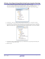
3.1
Choosing a Platform
The r_bsp provides board support packages for many boards. Choosing which one is currently being used is done by
modifying the platform.h header file found in the root of the r_bsp folder.
To choose a platform uncomment the #include for the board you are using. For example, to develop with a
RSK+RX63N board, uncomment the #include for ‘./board/rskrx63n/r_bsp.h’ macro and make sure all other board
#includes are commented out.
3.2
Platform Configuration
Once a platform has been chosen, it will need to be configured. The user configures their platform using a file named
r_bsp_config.h. Each platform has its own specific configuration file. This file is located in the platform’s board folder
and is named r_bsp_config_reference.h. To create an r_bsp_config.h file the user simply needs to copy the
r_bsp_config_reference.h file from their board folder, rename it to r_bsp_config.h, and put it somewhere in their
project where it can be included. The reference configuration file is provided so that users always have a known-good
configuration file if needed. It is recommended that the r_bsp_config.h file is stored in a folder named r_config in the
user’s project. This is not a requirement but all FIT Modules have configuration files and having one designated
location for these files makes them easy to find and easy to backup.
While each r_bsp_config.h file is different, there are many of the same options in each. The following sections will
provide details on these configuration options. Note that each macro starts with the common prefix ‘BSP_CFG_’ which
makes them easy to search for and easy for the user to identify.
R01AN1685EJ0310 Rev. 3.10
Dec. 1, 2015
Page 10 of 61
RX Family Board Support Package Module Using Firmware Integration Technology
3.2.1
MCU Product Part Number Information
The product part number for a MCU can provide the r_bsp with a lot of information about a MCU. For this reason, the
beginning of the configuration file has definitions that are set based on the MCU’s product part number. All of these
macros have a prefix of ‘BSP_CFG_MCU_PART_’. Some MCUs have more information in their product part numbers
than others but the table below shows the standard set that most have.
Define
Value
Meaning
BSP_CFG_MCU_PART_PACKAGE
See comments above #define in
r_bsp_config.h.
Defines which package is being
used. Depending on package sizes
MCUs will have different
numbers of pins and may have
more or less peripherals.
BSP_CFG_MCU_PART_MEMORY_SIZE
See comments above #define in
r_bsp_config.h.
Defines the sizes of ROM, RAM,
and Data Flash.
BSP_CFG_MCU_PART_GROUP
See comments above #define in
r_bsp_config.h.
Defines the MCU Group (e.g.
RX62N, RX63T) in a MCU
series.
BSP_CFG_MCU_PART_SERIES
See comments above #define in
r_bsp_config.h.
Defines the MCU Series (e.g.
RX600, RX200, RX100).
Table 3-1 : Product Part Number Defines
3.2.2
Stack & Heap Sizes
Stack sizes for RX devices are defined using the #pragma directives for the RX toolchain.
Define
Value
BSP_CFG_USER_STACK_ENABLE
#pragma stacksize su=
#pragma stacksize si=
BSP_CFG_HEAP_BYTES
0 = Use only Interrupt stack.
1 = Use Interrupt & User stacks.
Meaning
Whether to use 1 stack (Interrupt
stack) or 2 (Interrupt & User
stack). For further explanation
please see Section 2.8.
Size of User Stack in bytes.
Defines the size of the User stack.
This macro may be hidden from
view if the user has code folding
enabled in their editor.
Size of Interrupt Stack in bytes.
Defines the size of the Interrupt
stack. This macro may be hidden
from view if the user has code
folding enabled in their editor.
Size of heap in bytes.
Defines the size of the heap. To
disable heap please read the
comments above this #define.
Table 3-2 : Stack & Heap Defines
R01AN1685EJ0310 Rev. 3.10
Dec. 1, 2015
Page 11 of 61
RX Family Board Support Package Module Using Firmware Integration Technology
3.2.3
STDIO Enable
The use of the STDIO library requires extra code space, RAM space, and use of the heap. If the user does not require
the use of STDIO then it is recommended to disable it and save the extra memory.
Define
Value
Meaning
0 = Disable use of STDIO
BSP_CFG_IO_LIB_ENABLE
1 = Enable use of STDIO
Determines whether STDIO
initialization functions are called
at startup to setup the STDIO
libraries.
Table 3-3 : Stack & Heap Defines
3.2.4
CPU Modes & Boot Modes
RX MCUs have multiple boot modes including Serial Boot Mode, User Boot Mode, and Single-Chip Mode. RX610
and RX62x MCUs select which boot mode to use based on certain pin levels at startup. Later MCUs (e.g. RX63x,
RX200, RX100) require a pin to be set as well as setting a value in ROM.
Define
Value
BSP_CFG_RUN_IN_USER_MODE
BSP_CFG_USER_BOOT_ENABLE
Meaning
0 = Stay in Supervisor Mode
1 = Transition to User Mode
0 = Disable User Boot Mode
1 = Enable User Boot Mode
Out of reset RX MCUs operate in
Supervisor Mode. The user has the
option of transitioning to User
Mode (which has limited write
access to certain registers). Unless
needed it is recommended to keep
the MCU in Supervisor mode.
In order for RX63x, RX200, and
RX100 MCUs to enter User Boot
Mode a value in ROM must be
set. If this macro defines User
Boot Mode to be enabled then the
r_bsp will set the appropriate
ROM value.
Table 3-4 : CPU Modes & Boot Modes Defines
3.2.5
RTOS
Define
BSP_CFG_RTOS_USED
Value
0 = RTOS is not being used
1 = RTOS is being used
Meaning
Defines if a RTOS is being used in the
current application. Some FIT modules may
use this information for their own
configuration.
Table 3-5 RTOS Defines
R01AN1685EJ0310 Rev. 3.10
Dec. 1, 2015
Page 12 of 61
RX Family Board Support Package Module Using Firmware Integration Technology
3.2.6
Clock Setup
Available clocks vary amongst RX MCUs but the same basic concepts apply to all. After reset the r_bsp will initialize
the MCU clocks using the clock configuration macros found in r_bsp_config.h.
Define
Value
Meaning
0 = Low Speed On-Chip
Oscillator (LOCO)
BSP_CFG_CLOCK_SOURCE
1 = High Speed On-Chip
Oscillator (HOCO)
2 = Main Clock Oscillator
Defines which clock source will be in
use when the r_bsp code jumps to
main().
3 = Sub-Clock Oscillator
4 = PLL Circuit
BSP_CFG_PLL_SOURCE
BSP_CFG_USB_CLOCK_SOURCE
0 = Main clock
1 = HOCO
0 = System Clock (ICLK)
1 = USB PLL Circuit
Defines which clock source will be
used for the PLL Circuit
Defines which clock source will be
used when the USB peripheral is
enabled.
0 = Low Speed On-Chip
Oscillator (LOCO)
BSP_CFG_LCD_CLOCK_SOURCE
1 = High Speed On-Chip
Oscillator (HOCO)
2 = Main Clock Oscillator
Defines which clock source will be
used when LCD is enabled.
3 = Sub-Clock Oscillator
4 = IWDT dedicated clock
(IWDTCLK)
BSP_CFG_LCD_CLOCK_ENABLE
0 = LCD Source clock is
disabled
1 = LCD Source clock is
enabled
Defines if clock source to the LCD is
enabled.
0 = 16MHz
BSP_CFG_HOCO_FREQUENCY
1 = 18MHz
Defines the HOCO frequency.
2 = 20MHz
BSP_CFG_LPT_CLOCK_SOURCE
0 = Sub-Clock
1 = IWDT dedicated clock
Defines which clock source will be
used when the Low-Power Timer is
enabled.
BSP_CFG_XTAL_HZ
Input clock frequency in Hz.
Defines the input clock frequency.
This is used for calculating final clock
speeds.
BSP_CFG_PLL_DIV
PLL Input Frequency Divider
Defines the PLL divider to be used. If
the PLL is not used then this can be
ignored.
R01AN1685EJ0310 Rev. 3.10
Dec. 1, 2015
Page 13 of 61
RX Family Board Support Package Module Using Firmware Integration Technology
BSP_CFG_PLL_MUL
PLL Frequency
Multiplication Factor
Defines the PLL multiplier to be used.
If the PLL is not used then this can be
ignored.
BSP_CFG_UPLL_DIV
USB PLL Input Frequency
Divider
Defines the USB PLL divider to be
used. If the PLL is not used then this
can be ignored
BSP_CFG_UPLL_MUL
USB PLL Frequency
Multiplication Factor
Defines the USB PLL multiplier to be
used. If the PLL is not used then this
can be ignored
The divisor to use for this
clock.
RX MCUs have a number of clock
domains on-chip. Dividers can be set
for each of these independently to
maximize performance while
minimizing power consumption.
<ClockAcronym> is a placeholder for
the name of the clock to be set. For
example to set the divider for the CPU
clock (ICLK) then the user would set
the BSP_CFG_ICK_DIV macro.
BSP_CFG_<ClockAcronym>_DIV
Examples:
BSP_CFG_ICK_DIV
BSP_CFG_PCKA_DIV
BSP_CFG_PCKB_DIV
BSP_CFG_PCKD_DIV
BSP_CFG_FCK_DIV
0 = BCLK is not output
BSP_CFG_BCLK_OUTPUT
BSP_CFG_SDCLK_OUTPUT
1 = BCK frequency is output
2 = BCK/2 frequency is
output
0 = SDCLK is not output
1 = BCK frequency is output
0 = Use built-in clock code
BSP_CFG_USE_CGC_MODULE
1 = Use r_cgc_rx module for
clock management.
Defines if BCLK is output and if so
what frequency is output.
Defines if SDCLK is output.
Some RX Groups have the option of
enabling use of the r_cgc_rx module.
When this is enabled, the built-in
clock setup code will be removed and
replaced with calls to the r_cgc_rx
module. The r_cgc_rx module is more
sophisticated and offers many more
features than the built-in clock code,
including the ability to change clock
settings at run-time. If your
application does not require dynamic
clock changes then setting this to 0
will result in smaller code size.
Table 3-6 : Clock Setup Defines
R01AN1685EJ0310 Rev. 3.10
Dec. 1, 2015
Page 14 of 61
RX Family Board Support Package Module Using Firmware Integration Technology
3.2.7
Registers in ROM & External Memory Access Protection
Some registers are located in ROM and therefore must be set at compile-time. These include some option-setting
memory registers as well as certain memory protection registers.
RX MCUs have 2 different mechanisms for protecting MCU memory from being read after production. The first is the
use of ID codes. The RX ID code is 16 byte value that can be used to protect the MCU from being connected to a
debugger or from connecting in Serial Boot Mode. There are different settings that can be set for the ID code; please
refer to the hardware manual for your device for available options. The second mechanism is a 4 byte value called
ROM Code Protection. This value determines what read and write access parallel programmers have to the MCU.
Option-Setting Memory registers (i.e. OFS0, OFS1) can be set so that certain operations occur at reset. For example, the
IWDT can be configured and enabled, voltage detection can be enabled, and HOCO oscillation can be enabled. When
these registers are set the operations are completed before the MCU’s reset vector is fetched and execution begins.
Define
Value
BSP_CFG_ID_CODE_LONG_1
BSP_CFG_ID_CODE_LONG_2
BSP_CFG_ID_CODE_LONG_3
ID code setting in 4 byte
units.
BSP_CFG_ID_CODE_LONG_4
BSP_CFG_ROM_CODE_PROTECT_VALUE
0
= Read/Write access is
disabled
1
= Read access is
disabled
Meaning
Defines the ID code of the MCU.
The default value all 0xFF’s
means that protection is disabled.
NOTE: if the ID code is set then
it should be remembered because
the code will be required if the
MCU is going to be connected for
debugging or in Serial Boot Mode
again.
Defines the read and write access
allowed by parallel programmers.
Else = Read/Write access is
enabled
BSP_CFG_OFS0_REG_VALUE
Value to be written to OFS0
register.
Defines the 4-byte value to be
programmed into the OFS0 ROM
location.
BSP_CFG_OFS1_REG_VALUE
Value to be written to OFS1
register.
Defines the 4-byte value to be
programmed into the OFS1 ROM
location.
BSP_CFG_TRUSTED_MODE_FUNCTION
Value to be written to TMEF
register.
Defines if Trusted Mode is
enabled or disabled for RX64M
and RX71M MCU’s.
Table 3-7 : ROM Register Defines
3.2.8
Atomic Locking
For an introduction into the r_bsp’s atomic locking see 2.17. These macros allow the user to override the default
locking mechanisms and implement their own. A user might wish to do this in order to replace the simple default
mechanisms provided in the r_bsp with more feature rich objects such as semaphores or mutexes from their RTOS. If
the user wished to do this they would first configure the r_bsp to use user defined locking mechanisms (see
BSP_CFG_USER_LOCKING_ENABLED below). After that they would define BSP_CFG_USER_LOCKING_TYPE
to be the type they wished to use for their locks. If using an RTOS semaphore then its type would be used here. Finally
the user would need to define the four locking functions that would be used (see last 4 entries in table below). The
arguments to these user defined functions have to match the arguments sent to the default locking functions. After these
changes are made all locks in the user’s project would be converted to the user defined locks. Whenever the r_bsp lock
functions are called by user code, or FIT Module code, the user’s functions would be called. At this point the user is
R01AN1685EJ0310 Rev. 3.10
Dec. 1, 2015
Page 15 of 61
RX Family Board Support Package Module Using Firmware Integration Technology
responsible for implementing the locking features. Inside these functions the user would be free to use the more
advanced locking features of their RTOS.
Define
Value
BSP_CFG_USER_LOCKING_ENABLED
0 = Use default locking
mechanisms
1 = Use user defined
locking mechanisms
Meaning
The default locking mechanisms
provided with the r_bsp do not use an
RTOS and therefore do not offer
some of the advanced features that a
user might expect from an RTOS
when using a semaphore or mutex.
BSP_CFG_USER_LOCKING_TYPE
Data type to be used for
locks (default is
bsp_lock_t)
If the user decides to use their own
locking mechanism then the data type
for their locks should be defined here.
For example, if the user replaces the
default locks with an RTOS
semaphore or mutex then that data
type would be specified here.
BSP_CFG_USER_LOCKING_HW
_LOCK_FUNCTION
User defined functions to
be called when r_bsp
lock functions are
overridden by user.
If the user is using their own locking
mechanisms then the function
defined by this macro will be called
when R_BSP_HardwareLock() is
called.
BSP_CFG_USER_LOCKING_HW
_UNLOCK_FUNCTION
User defined functions to
be called when r_bsp
lock functions are
overridden by user.
If the user is using their own locking
mechanisms then the function
defined by this macro will be called
when R_BSP_HardwareUnlock() is
called.
BSP_CFG_USER_LOCKING_SW
_LOCK_FUNCTION
User defined functions to
be called when r_bsp
lock functions are
overridden by user.
If the user is using their own locking
mechanisms then the function
defined by this macro will be called
when R_BSP_SoftwareLock() is
called.
BSP_CFG_USER_LOCKING_SW
_UNLOCK_FUNCTION
User defined functions to
be called when r_bsp
lock functions are
overridden by user.
If the user is using their own locking
mechanisms then the function
defined by this macro will be called
when R_BSP_SoftwareUnlock() is
called.
Table 3-8 : Atomic Locking Defines
R01AN1685EJ0310 Rev. 3.10
Dec. 1, 2015
Page 16 of 61
RX Family Board Support Package Module Using Firmware Integration Technology
3.2.9
Parameter Checking
This macro is a global setting for enabling or disabling parameter checking. Each FIT module will also have its own
local macro for this same purpose. By default the local macros will take the global value from here though they can be
overridden. Therefore, the local setting has priority over this global setting. Disabling parameter checking should only
be performed when inputs are known to be good and the increase in speed or decrease in code space is needed.
Define
Value
BSP_CFG_PARAM_CHECKING_ENABLE
Meaning
0 = Parameter checking disabled
1 = Parameter checking enabled
Defines whether the global
setting for parameter checking is
enabled or disabled. Local
modules will take this value by
default but can be locally
overridden.
Table 3-9 : Parameter Checking Defines
3.2.10
MCU Voltage
Define
Value
BSP_CFG_MCU_VCC_MV
Voltage supplied to MCU (Vcc)
in millivolts.
Meaning
Some FIT Modules (e.g. LVD) need to
know the voltage supplied to the MCU.
This information is obtained from here.
Table 3-10 : MCU Voltage Defines
R01AN1685EJ0310 Rev. 3.10
Dec. 1, 2015
Page 17 of 61
RX Family Board Support Package Module Using Firmware Integration Technology
4. API Information
This Driver API follows the Renesas API naming standards.
4.1
Hardware Requirements
Not Applicable.
4.2
Hardware Resource Requirements
Not Applicable.
4.3
Software Requirements
None.
4.4
Limitations
None.
4.5
Supported Toolchains
This driver is tested and working with the following toolchains:
4.6
•
Renesas RX Toolchain v.2.01.00 (RX110, RX111, RX113, RX210, RX21A, RX220, RX231, RX610, RX62N,
RX62T, RX62G, RX630, RX631, RX63N, RX63T, RX64M, RX71M)
•
Renesas RX Toolchain v.2.03.00 (RX23T, RX130)
Header Files
All API calls are accessed by including a single file platform.h which is supplied with this driver’s project code.
4.7
Integer Types
This project uses ANSI C99 “Exact width integer types” in order to make the code clearer and more portable. These
types are defined in stdint.h.
4.8
Configuration Overview
For configuration information please see Section 3.
R01AN1685EJ0310 Rev. 3.10
Dec. 1, 2015
Page 18 of 61
RX Family Board Support Package Module Using Firmware Integration Technology
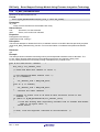
4.9
4.9.1
API Data Structures
Software Lock
This data structure is used for implementing atomic locking on RX MCUs. The lock member must be 4-bytes in order
to use the RX’s atomic XCHG instruction. This structure is the default type defined by the
BSP_CFG_USER_LOCKING_TYPE macro.
typedef struct
{
/* The actual lock. int32_t is used because this is what the xchg()
instruction takes as parameters. */
int32_t
lock;
} bsp_lock_t;
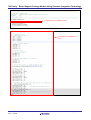
4.9.2
Interrupt Callback Parameter
This data structure is used when calling an interrupt callback function. The interrupt handler will fill in this structure,
cast it as ‘(void *)’, and then send it as the argument to the callback function.
typedef struct
{
bsp_int_src_t vector;
} bsp_int_cb_args_t;
4.10
4.10.1
//Which vector caused this interrupt
API Typedefs
Register Protection
This typedef defines the different register protection options that can be toggled. Notice that some registers are grouped
together. For example, LPC, CGC, and software reset registers are all protected by the same bit. Which items, and how
many, are in this typedef will vary depending on the MCU being used. Please reference cpu.h for your MCU to see the
valid options for your MCU. The typedef below belongs to the RX111.
/* The different types of registers that can be protected. */
typedef enum
{
/* Enables writing to the registers related to the clock generation circuit:
SCKCR, SCKCR3, PLLCR, PLLCR2, MOSCCR, SOSCCR,LOCOCR, ILOCOCR, HOCOCR,
OSTDCR, OSTDSR, CKOCR. */
BSP_REG_PROTECT_CGC = 0,
/* Enables writing to the registers related to operating modes, low power
consumption, the clock generation circuit, and software reset: SYSCR1,
SBYCR, MSTPCRA, MSTPCRB, MSTPCRC, OPCCR, RSTCKCR, SOPCCR, MOFCR, MOSCWTCR,
SWRR. */
BSP_REG_PROTECT_LPC_CGC_SWR,
/* Enables writing to the HOCOWTCR register. */
BSP_REG_PROTECT_HOCOWTCR,
/* Enables writing to the registers related to the LVD: LVCMPCR, LVDLVLR,
LVD1CR0, LVD1CR1, LVD1SR, LVD2CR0, LVD2CR1, LVD2SR. */
BSP_REG_PROTECT_LVD,
/* Enables writing to MPC's PFS registers. */
BSP_REG_PROTECT_MPC,
/* This entry is used for getting the number of enum items. This must be the
last entry. DO NOT REMOVE THIS ENTRY!*/
BSP_REG_PROTECT_TOTAL_ITEMS
} bsp_reg_protect_t;
R01AN1685EJ0310 Rev. 3.10
Dec. 1, 2015
Page 19 of 61
RX Family Board Support Package Module Using Firmware Integration Technology
4.10.2
Hardware Resource Locks
This typedef defines the available hardware resource locks. For each entry in this enum one software lock will be
allocated in the hardware lock array. Which items are in this list, and how many, will vary depending on the MCU
chosen. The typedef below is for the RX111.
typedef enum
{
BSP_LOCK_BSC = 0,
BSP_LOCK_CAC,
BSP_LOCK_CMT,
BSP_LOCK_CMT0,
BSP_LOCK_CMT1,
BSP_LOCK_CRC,
BSP_LOCK_DA,
BSP_LOCK_DOC,
BSP_LOCK_DTC,
BSP_LOCK_ELC,
BSP_LOCK_FLASH,
BSP_LOCK_ICU,
BSP_LOCK_IRQ0,
BSP_LOCK_IRQ1,
BSP_LOCK_IRQ2,
BSP_LOCK_IRQ3,
BSP_LOCK_IRQ4,
BSP_LOCK_IRQ5,
BSP_LOCK_IRQ6,
BSP_LOCK_IRQ7,
BSP_LOCK_IWDT,
BSP_LOCK_MPC,
BSP_LOCK_MTU,
BSP_LOCK_MTU0,
BSP_LOCK_MTU1,
BSP_LOCK_MTU2,
BSP_LOCK_MTU3,
BSP_LOCK_MTU4,
BSP_LOCK_MTU5,
BSP_LOCK_POE,
BSP_LOCK_RIIC0,
BSP_LOCK_RSPI0,
BSP_LOCK_RTC,
BSP_LOCK_RTCB,
BSP_LOCK_S12AD,
BSP_LOCK_SCI1,
BSP_LOCK_SCI5,
BSP_LOCK_SCI12,
BSP_LOCK_SMCI1,
BSP_LOCK_SMCI5,
BSP_LOCK_SMCI12,
BSP_LOCK_SYSTEM,
BSP_LOCK_USB0,
BSP_NUM_LOCKS
/* This entry is not a valid lock. It is used for sizing
g_bsp_Locks[] array below. Do not touch! */
} mcu_lock_t;
R01AN1685EJ0310 Rev. 3.10
Dec. 1, 2015
Page 20 of 61
RX Family Board Support Package Module Using Firmware Integration Technology
4.10.3
Interrupt Error Codes
This typedef defines the error codes that can be returned by the R_BSP_InterruptWrite(), R_BSP_InterruptRead(), and
R_BSP_InterruptControl() functions.
The typedef below is for the RX111.
Other RX MCU’s may support additional interrupt control commands.
typedef enum
{
BSP_INT_SUCCESS = 0,
BSP_INT_ERR_NO_REGISTERED_CALLBACK, //There is not a registered callback
//for this interrupt source
BSP_INT_ERR_INVALID_ARG,
//Illegal argument input
BSP_INT_ERR_UNSUPPORTED
//Operation is not supported by this API
} bsp_int_err_t;
4.10.4
Interrupt Control Commands
This typedef defines the available commands that can be used with the R_BSP_InterruptControl() function.
The typedef below is for the RX111.
Other RX MCU’s may support additional interrupt control commands
typedef enum
{
BSP_INT_CMD_CALL_CALLBACK = 0, //Calls registered callback function
//if one exists
BSP_INT_CMD_INTERRUPT_ENABLE, //Enables a give interrupt (Available for NMI
//pin, FPU, and Bus Error)
BSP_INT_CMD_INTERRUPT_DISABLE //Disables a given interrupt (Available for
//FPU, and Bus Error)
} bsp_int_cmd_t;
4.10.5
Interrupt Callback Function
This typedef defines the callback function type. Callback functions should have a ‘void’ return type and should take an
argument of type ‘void *’.
typedef void (*bsp_int_cb_t)(void *);
R01AN1685EJ0310 Rev. 3.10
Dec. 1, 2015
Page 21 of 61
RX Family Board Support Package Module Using Firmware Integration Technology
4.10.6
Interrupt Sources
This typedef defines the interrupt vectors that can have callbacks registered to them. Note that the options in this
typedef will vary depending on which MCU is being used. The typedef below is for the RX111. Other RX MCU’s may
support additional interrupt sources.
typedef enum
{
BSP_INT_SRC_EXC_SUPERVISOR_INSTR = 0, //Occurs when privileged instruction
//is executed in User Mode
BSP_INT_SRC_EXC_UNDEFINED_INSTR,
//Occurs when MCU encounters an
//unknown instruction
BSP_INT_SRC_EXC_NMI_PIN,
//NMI Pin interrupt
BSP_INT_SRC_EXC_FPU,
//FPU exception
BSP_INT_SRC_OSC_STOP_DETECT,
//Oscillation stop is detected
BSP_INT_SRC_WDT_ERROR,
//WDT underflow/refresh error has
//occurred
BSP_INT_SRC_IWDT_ERROR,
//IWDT underflow/refresh error has
//occurred
BSP_INT_SRC_LVD1,
//Voltage monitoring 1 interrupt
BSP_INT_SRC_LVD2,
//Voltage monitoring 2 interrupt
BSP_INT_SRC_UNDEFINED_INTERRUPT,
//Interrupt has triggered for a vector
//that user did not write a handler
//for
BSP_INT_SRC_BUS_ERROR,
//Bus error: illegal address access or
//timeout
BSP_INT_SRC_TOTAL_ITEMS
//DO NOT MODIFY! This is used for
//sizing the interrupt callback array.
} bsp_int_src_t;
4.10.7
Group Interrupts
4.10.8
Software Configurable Interrupts
The RX64M MCU supports group interrupts, where (up to 32) multiple peripheral interrupt requests are grouped
together as one interrupt request. Interrupts are grouped depending on the peripheral operating clock (PCLKA or
PCLKB) and method to detect interrupt requests (edge or level detection). When a group interrupt request is generated,
the source of the interrupt may be identified by examining the respective (A or B, edge or level) Group Interrupt
Request Register.
The RX64M MCU allows peripheral interrupt sources to be dynamically assigned to a vector number from 128 to 255.
Based on the peripheral operating clock they are divided into software configurable interrupt A and software
configurable interrupt B. Software configurable interrupt B may be used for peripherals that operate in synchronization
with PCLKB and can be assigned to interrupt numbers 128 – 207.
Software configurable interrupt A may be used for peripherals that operate in synchronization with PCKLA and can be
assigned to interrupt numbers 208 – 255.
4.11
Return Values
None.
4.12
Adding Driver to Your Project
Please see Section 6.
R01AN1685EJ0310 Rev. 3.10
Dec. 1, 2015
Page 22 of 61
RX Family Board Support Package Module Using Firmware Integration Technology
5. API Functions
5.1
Summary
The following functions are included in this design:
Function
Description
R_BSP_GetVersion
Returns version of r_bsp
R_BSP_InterruptsDisable
Globally disables interrupts
R_BSP_InterruptsEnable
Globally enables interrupts
R_BSP_CpuInterruptLevelRead
Reads the CPU’s Interrupt Priority Level
R_BSP_CpuInterruptLevelWrite
Writes the CPU’s Interrupt Priority Level
R_BSP_RegisterProtectEnable
Enables write protection for selected registers
R_BSP_RegisterProtectDisable
Disables write protection for selected registers
R_BSP_SoftwareLock
Attempts to reserve a lock
R_BSP_SoftwareUnlock
Releases a lock
R_BSP_HardwareLock
Attempts to reserve a hardware peripheral lock
R_BSP_HardwareUnlock
Releases a hardware peripheral lock
R_BSP_InterruptWrite
Registers a callback function for an interrupt
R_BSP_InterruptRead
Gets the callback for an interrupt if one is registered.
R_BSP_InterruptControl
Executes various other interrupt features.
R_BSP_SoftwareDelay
Delays the specified duration.
R01AN1685EJ0310 Rev. 3.10
Dec. 1, 2015
Page 23 of 61
RX Family Board Support Package Module Using Firmware Integration Technology
5.2
R_BSP_GetVersion
Returns the current version of the r_bsp.
Format
uint32_t R_BSP_GetVersion(void);
Parameters
None.
Return Values
Version of the r_bsp.
Properties
Prototyped in file “r_bsp_common.h”
Implemented in file “r_bsp_common.c”
Description
This function will return the version of the currently installed r_bsp. The version number is encoded where
the top 2 bytes are the major version number and the bottom 2 bytes are the minor version number. For
example, Version 4.25 would be returned as 0x00040019.
Reentrant
Yes.
Example
uint32_t cur_version;
/* Get version of installed r_bsp. */
cur_version = R_BSP_GetVersion();
/* Check to make sure version is new enough for this application’s use. */
if (MIN_VERSION > cur_version)
{
/* This r_bsp version is not new enough and does not have XXX feature
that is needed by this application. Alert user. */
....
}
Special Notes:
•
This function is specified to be an inline function in r_bsp_common.c.
R01AN1685EJ0310 Rev. 3.10
Dec. 1, 2015
Page 24 of 61
RX Family Board Support Package Module Using Firmware Integration Technology
5.3
R_BSP_InterruptsDisable
Globally disables interrupts.
Format
void R_BSP_InterruptsDisable(void);
Parameters
None.
Return Values
None.
Properties
Prototyped in file “cpu.h”
Implemented in file “cpu.c”
Description
This function globally disables interrupts. This is performed by clearing the ‘I’ bit in the CPU’s Processor
Status Word (PSW) register.
Reentrant
Yes.
Example
/* Disable interrupts so that accessing this critical area will be guaranteed
to be atomic. */
R_BSP_InterruptsDisable();
/* Access critical resource while interrupts are disabled */
....
/* End of critical area. Enable interrupts. */
R_BSP_InterruptsEnable();
Special Notes:
•
The ‘I’ bit of the PSW can only be modified when in Supervisor Mode. If the CPU is in User Mode
and this function is called then a Privileged Instruction Exception will occur.
R01AN1685EJ0310 Rev. 3.10
Dec. 1, 2015
Page 25 of 61
RX Family Board Support Package Module Using Firmware Integration Technology
5.4
R_BSP_InterruptsEnable
Globally enables interrupts.
Format
void R_BSP_InterruptsEnable(void);
Parameters
None.
Return Values
None.
Properties
Prototyped in file “cpu.h”
Implemented in file “cpu.c”
Description
This function globally enables interrupts. This is performed by setting the ‘I’ bit in the CPU’s Processor Status
Word (PSW) register.
Reentrant
Yes.
Example
/* Disable interrupts so that accessing this critical area will be guaranteed
to be atomic. */
R_BSP_InterruptsDisable();
/* Access critical resource while interrupts are disabled */
....
/* End of critical area. Enable interrupts. */
R_BSP_InterruptsEnable();
Special Notes:
•
The ‘I’ bit of the PSW can only be modified when in Supervisor Mode. If the CPU is in User Mode
and this function is called then a Privileged Instruction Exception will occur.
R01AN1685EJ0310 Rev. 3.10
Dec. 1, 2015
Page 26 of 61
RX Family Board Support Package Module Using Firmware Integration Technology
5.5
R_BSP_CpuInterruptLevelRead
Reads the CPU’s Interrupt Priority Level.
Format
uint32_t R_BSP_CpuInterruptLevelRead(void);
Parameters
None.
Return Values
The CPU’s Interrupt Priority Level.
Properties
Prototyped in file “cpu.h”
Implemented in file “cpu.c”
Description
This function reads the CPU’s Interrupt Priority Level. This is level is stored in the IPL bits of the Processor
Status Word (PSW) register.
Reentrant
Yes.
Example
uint32_t cpu_ipl;
/* Read the CPU’s Interrupt Priority Level. */
cpu_ipl = R_BSP_CpuInterruptLevelRead();
Special Notes:
None.
R01AN1685EJ0310 Rev. 3.10
Dec. 1, 2015
Page 27 of 61
RX Family Board Support Package Module Using Firmware Integration Technology
5.6
R_BSP_CpuInterruptLevelWrite
Writes the CPU’s Interrupt Priority Level.
Format
bool R_BSP_CpuInterruptLevelWrite(uint32_t level);
Parameters
level
The level to write to the CPU’s IPL.
Return Values
true:
false:
Successful, CPU’s IPL has been written
Failure, provided ‘level’ has invalid IPL value
Properties
Prototyped in file “cpu.h”
Implemented in file “cpu.c”
Description
This function writes the CPU’s Interrupt Priority Level. This is level is stored in the IPL bits of the Processor
Status Word (PSW) register. This function does check to make sure that the IPL being written is valid. The
maximum and minimum valid settings for the CPU IPL are defined in mcu_info.h using the
BSP_MCU_IPL_MAX and BSP_MCU_IPL_MIN macros.
Reentrant
Yes.
Example
/* Response time is critical during this portion of the application. Set the
CPU’s Interrupt Priority Level so that interrupts below the set
threshold are disabled. Interrupt vectors with IPLs higher than this
threshold will still be accepted and will not have to contend with the
lower priority interrupts. */
if (false == R_BSP_CpuInterruptLevelWrite(HIGH_PRIORITY_THRESHOLD))
{
/* Error in setting CPU’s IPL. Invalid IPL was provided. */
....
}
/* Only high priority interrupts (as defined by user) will be accepted during
this period. */
....
/* Time sensitive period is over. Set CPU’s IPL back to lower value so that
lower priority interrupts can now be serviced again. */
if (false == R_BSP_CpuInterruptLevelWrite(LOW_PRIORITY_THRESHOLD))
{
/* Error in setting CPU’s IPL. Invalid IPL was provided. */
....
}
Special Notes:
•
The CPU’s IPL can only be modified by the user when in Supervisor Mode. If the CPU is in User
Mode and this function is called then a Privileged Instruction Exception will occur.
R01AN1685EJ0310 Rev. 3.10
Dec. 1, 2015
Page 28 of 61
RX Family Board Support Package Module Using Firmware Integration Technology
5.7
R_BSP_RegisterProtectEnable
Enables write protection for selected registers.
Format
void R_BSP_RegisterProtectEnable(bsp_reg_protect_t regs_to_protect);
Parameters
regs_to_protect
Which registers to enable write protection for.
Return Values
None.
Properties
Prototyped in file “cpu.h”
Implemented in file “cpu.c”
Description
This function enables write protection for the input registers. Only certain MCU registers have the ability to
be write protected. To see which registers are available to be protected by this function look at the
bsp_reg_protect_t enum in cpu.h for your MCU.
This function, and R_BSP_RegisterProtectDisable(), use counters for each entry in the bsp_reg_protect_t
enum so that users can call these functions multiple times without problem. An example of why this is
needed is shown below in the Special Notes section below.
Reentrant
No.
Example
/* Write access must be enabled before writing to MPC registers. */
R_BSP_RegisterProtectDisable(BSP_REG_PROTECT_MPC);
/* MPC registers are now writable. */
/* Setup Port 2 Pin 6 as TXD1 for SCI1. */
MPC.P26PFS.BYTE = 0x0A;
/* Setup Port 4 Pin 2 as AD input for potentiometer. */
MPC.P42PFS.BYTE = 0x80;
/* More pin setup. */
....
/* Enable write protection for MPC registers to protect against accidental
writes. */
R_BSP_RegisterProtectEnable(BSP_REG_PROTECT_MPC);
R01AN1685EJ0310 Rev. 3.10
Dec. 1, 2015
Page 29 of 61
RX Family Board Support Package Module Using Firmware Integration Technology
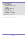
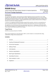
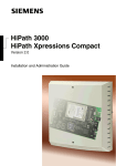
Special Notes:
This is an example showing why counters are needed for register protection.
1. The user’s application calls the open function for r_module1.
2. r_module1 disables write protection for some registers that are required to be written during
initialization of this module by calling R_BSP_RegisterProtectDisable(). At this point the counter for
this protected registers is incremented by 1.
3. r_module1 writes to unprotected registers that were made writable by previous step.
4. r_module1 also depends upon r_module2 and needs to call its open function, R_MODULE2_Open().
5. In the r_module2 function it also needs to write to the same protected registers as r_module1.
r_module2 calls R_BSP_RegisterProtectDisable() again since it does not know that r_module1
already enabled write access to these registers. The counter for the protected register is
incremented by 1 and is now 2.
6. r_module2 writes to unprotected registers that were made writable by previous step.
7. r_module2 is done writing to the protected registers so it calls R_BSP_RegisterProtectEnable() to reenable write protection for the registers. The counter for the protected register is decremented by 1
and is now 1. Since the counter is not 0 the code knows that it should not actually re-enable
protection yet.
8. Execution goes back to R_MODULE1_Open() where it continues to write to registers. Here is where
the problem can occur. If counters are not used then the call to R_BSP_RegisterProtectEnable() by
r_module2 (Step #7) can prevent the registers in r_module1 from being written.
9. r_module1 is done writing to the protected registers so it calls R_BSP_RegisterProtectEnable() to reenable write protection for the registers. The counter for the protected register is decremented by 1
and is now 0. Since the counter is 0 the API code knows that it is safe to re-enable write protection
for the registers.
Figure 5-1 : Register Protection Example
R01AN1685EJ0310 Rev. 3.10
Dec. 1, 2015
Page 30 of 61
RX Family Board Support Package Module Using Firmware Integration Technology
5.8
R_BSP_RegisterProtectDisable
Disables write protection for selected registers.
Format
void R_BSP_RegisterProtectDisable(bsp_reg_protect_t regs_to_protect);
Parameters
regs_to_protect
Which registers to disable write protection for.
Return Values
None.
Properties
Prototyped in file “cpu.h”
Implemented in file “cpu.c”
Description
This function disables write protection for the input registers. Only certain MCU registers have the ability to
be write protected. To see which registers are available to be protected by this function look at the
bsp_reg_protect_t enum in cpu.h for your MCU.
This function, and R_BSP_RegisterProtectEnable(), use counters for each entry in the bsp_reg_protect_t
enum so that users can call these functions multiple times without problem. An example of why this is
needed is shown in the Special Notes section of Section 5.7.
Reentrant
No.
Example
/* Write access must be enabled before writing to CGC registers. */
R_BSP_RegisterProtectDisable(BSP_REG_PROTECT_CGC);
/* CGC registers are spread amongst two protection bits. */
R_BSP_RegisterProtectDisable(BSP_REG_PROTECT_LPC_CGC_SWR);
/* CGC registers are now writable. */
/* Select PLL as clock source. */
SYSTEM.SCKCR3.WORD = 0x0400;
/* More clock setup. */
....
/* Enable write protection for CGC registers to protect against accidental
writes. */
R_BSP_RegisterProtectEnable(BSP_REG_PROTECT_CGC);
R_BSP_RegisterProtectEnable(BSP_REG_PROTECT_LPC_CGC_SWR);
Special Notes:
None.
R01AN1685EJ0310 Rev. 3.10
Dec. 1, 2015
Page 31 of 61
RX Family Board Support Package Module Using Firmware Integration Technology
5.9
R_BSP_SoftwareLock
Attempts to reserve a lock.
Format
bool R_BSP_SoftwareLock(BSP_CFG_USER_LOCKING_TYPE * const plock);
Parameters
plock
Pointer to lock structure with lock to try and acquire.
Return Values
true:
false:
Successful, lock was available and acquired
Failure, lock was already acquired and is not available
Properties
Prototyped in file “locking.h”
Implemented in file “locking.c”
Description
This function implements an atomic locking mechanism. Locks can be used in numerous ways. Two
common uses of locks are to protect critical sections of code and to protect against duplicate resource
allocation. For protecting critical sections of code the user would require that the code first obtain the critical
section’s lock before executing. An example of protecting against duplicate resource allocation would be if
the user had two FIT modules that used the same peripheral. For example, the user may have one FIT
module that uses the SCI peripheral in UART mode and another FIT module that uses the SCI peripheral in
I2C mode. To make sure that both modules cannot use the same SCI channel, locks can be used.
Care should be taken when using locks as they do not provide advanced features one might expect from an
RTOS semaphore or mutex. If used improperly locks can lead to deadlock in the user’s system.
Users can override the default locking mechanisms. See Section 3.2.8 for more information.
Reentrant
Yes.
Example
This shows an example of using locks with the Virtual EEPROM code. This FIT module does not access any
peripherals directly, but still needs protection against reentrancy.
/* Used for locking state of VEE */
static BSP_CFG_USER_LOCKING_TYPE g_vee_lock;
/*******************************************************************************
* Function Name: vee_lock_state
* Description : Tries to lock the VEE state
* Arguments
: state *
Which state to try to transfer to
* Return value : VEE_SUCCESS *
Successful, state taken
*
VEE_BUSY *
Data flash is busy, state not taken
*******************************************************************************/
static uint8_t vee_lock_state (vee_states_t state)
{
/* Local return variable */
uint8_t ret = VEE_SUCCESS;
/* Try to lock VEE to change state. */
/* Check to see if lock was successfully taken. */
if(false == R_BSP_SoftwareLock(&g_vee_lock))
{
/* Another operation is on-going */
return VEE_BUSY;
}
R01AN1685EJ0310 Rev. 3.10
Dec. 1, 2015
Page 32 of 61
RX Family Board Support Package Module Using Firmware Integration Technology
/* Check VEE status to make sure we are not interfering with another
thread */
if( state == VEE_READING )
{
/* If another read comes in while the state is reading then we are OK */
if( ( g_vee_state != VEE_READY ) && ( g_vee_state != VEE_READING) )
{
/* VEE is busy */
ret = VEE_BUSY;
}
}
else
{
/* If we are doing something other than reading then we must be in the
VEE_READY state */
if( g_vee_state != VEE_READY )
{
/* VEE is busy */
ret = VEE_BUSY;
}
}
if( ret == VEE_SUCCESS )
{
/* Lock state */
g_vee_state = state;
}
/* Release lock. */
R_BSP_SoftwareUnlock(&g_vee_lock);
}
return ret;
Special Notes:
None.
R01AN1685EJ0310 Rev. 3.10
Dec. 1, 2015
Page 33 of 61
RX Family Board Support Package Module Using Firmware Integration Technology
5.10
R_BSP_SoftwareUnlock
Releases a lock.
Format
bool R_BSP_SoftwareUnlock(BSP_CFG_USER_LOCKING_TYPE * const plock);
Parameters
plock
Pointer to lock structure with lock to release.
Return Values
true:
false:
Successful, lock was released
Failure, lock could not be released
Properties
Prototyped in file “locking.h”
Implemented in file “locking.c”
Description
This function releases a lock that was previously acquired using the R_BSP_SoftwareLock() function. Please
see Section 5.9 for more information on locks.
Reentrant
Yes.
Example
This shows an example of using locks for a critical section of code.
/* Used for locking critical section of code. */
static BSP_CFG_USER_LOCKING_TYPE g_critical_lock;
static bool critical_area_example (void)
{
/* Try to acquire lock for executing critical section below. */
if(false == R_BSP_SoftwareLock(&g_critical_lock))
{
/* Lock has already been acquired. */
return false;
}
/* BEGIN CRITICAL SECTION. */
/* Execute critical section. */
....
/* END CRITICAL SECTION. */
/* Release lock. */
R_BSP_SoftwareUnlock(&g_critical_lock);
}
return true;
Special Notes:
None.
R01AN1685EJ0310 Rev. 3.10
Dec. 1, 2015
Page 34 of 61
RX Family Board Support Package Module Using Firmware Integration Technology
5.11
R_BSP_HardwareLock
Attempts to reserve a hardware peripheral lock.
Format
bool R_BSP_HardwareLock(mcu_lock_t const hw_index);
Parameters
hw_index
Index of lock to acquire from the hardware lock array.
Return Values
true:
false:
Successful, lock was available and acquired
Failure, lock was already acquired and is not available
Properties
Prototyped in file “locking.h”
Implemented in file “locking.c”
Description
This function attempts to acquire the lock for a hardware resource of the MCU. Instead of sending in a
pointer to a lock as with the R_BSP_SoftwareLock() function, the user sends in an index to an array that
holds 1 lock per MCU hardware resource. This array is shared amongst all FIT modules and user code
therefore allowing multiple FIT modules (and user code) to use the same locks. The user can see the
available hardware resources by looking at the mcu_lock_t enum in mcu_locks.h. These enum values are
also the index into the hardware lock array. The same atomic locking mechanisms from the
R_BSP_SoftwareLock() function are used with this function as well.
Reentrant
Yes.
Example
This example shows hardware locks being used to control access to a RSPI channel.
/******************************************************************************
* Function Name: R_RSPI_Send
* Description : Send data over RSPI channel.
* Arguments
: channel *
Which channel to use.
*
pdata *
Pointer to data to transmit
*
bytes *
Number of bytes to transmit
* Return Value : true *
Data sent successfully.
*
false *
Could not obtain lock.
******************************************************************************/
bool R_RSPI_Send(uint8_t channel, uint8_t * pdata, uint32_t bytes)
{
mcu_lock_t rspi_channel_lock;
/* Check and make sure channel is valid. */
...
/* Use appropriate RSPI channel lock. */
if (0 == channel)
{
rspi_channel_lock = BSP_LOCK_RSPI0;
}
else
{
rspi_channel_lock = BSP_LOCK_RSPI1;
}
R01AN1685EJ0310 Rev. 3.10
Dec. 1, 2015
Page 35 of 61
RX Family Board Support Package Module Using Firmware Integration Technology
/* Attempt to obtain lock so we know we have exclusive access to RSPI
channel. */
if (false == R_BSP_HardwareLock(rspi_channel_lock))
{
/* Lock has already been acquired by another task. Need to try again
later. */
return false;
}
/* Else, lock was acquired. Continue on with send operation. */
...
/* Now that send operation is completed, release hold on lock so that other
tasks may use this RSPI channel. */
R_BSP_HardwareUnlock(rspi_channel_lock);
}
return true;
Special Notes:
Each entry in the mcu_lock_t enum in mcu_locks.h will be allocated a lock. On RX MCUs, each lock is
required to be 4-bytes. If RAM space is an issue then the user can remove the entries from the mcu_lock_t
enum that they are not using. For example, if the user is not using the CRC peripheral then they could delete
the BSP_LOCK_CRC entry. The user will save 4-bytes per deleted entry.
R01AN1685EJ0310 Rev. 3.10
Dec. 1, 2015
Page 36 of 61
RX Family Board Support Package Module Using Firmware Integration Technology
5.12
R_BSP_HardwareUnlock
Releases a hardware peripheral lock.
Format
bool R_BSP_HardwareUnlock(mcu_lock_t const hw_index);
Parameters
hw_index
Index of lock to release from the hardware lock array.
Return Values
true:
false:
Successful, lock was released
Failure, lock could not be released
Properties
Prototyped in file “locking.h”
Implemented in file “locking.c”
Description
This function attempts to release the lock for a hardware resource of the MCU that was previously acquired
using the R_BSP_HardwareLock() function. For more information on hardware locks please see Section
5.11.
Reentrant
Yes.
Example
This example shows hardware locks being used to prevent duplicate hardware resource allocation. The
R_SCI_Open() function takes the lock so all modules know that the SCI channel is being used.
R_SCI_Close() releases the lock thereby making it available for any module to use.
bool R_SCI_Open(uint8_t channel, ...)
{
mcu_lock_t sci_channel_lock;
/* Check and make sure channel is valid. */
...
/* Use appropriate RSPI channel lock. */
if (0 == channel)
{
sci_channel_lock = BSP_LOCK_SCI0;
}
else if (1 == channel)
{
sci_channel_lock = BSP_LOCK_SCI1;
}
... continue for other channels ...
/* Attempt to obtain lock so we know we have exclusive access to SCI
channel. */
if (false == R_BSP_HardwareLock(sci_channel_lock))
{
/* Lock has already been acquired by another task or another FIT module.
Need to try again later. */
return false;
}
}
/* Else, lock was acquired. Continue on initialization. */
...
R01AN1685EJ0310 Rev. 3.10
Dec. 1, 2015
Page 37 of 61
RX Family Board Support Package Module Using Firmware Integration Technology
bool R_SCI_Close(uint8_t channel, ...)
{
mcu_lock_t sci_channel_lock;
/* Check and make sure channel is valid. */
...
/* Use appropriate RSPI channel lock. */
if (0 == channel)
{
sci_channel_lock = BSP_LOCK_SCI0;
}
else if (1 == channel)
{
sci_channel_lock = BSP_LOCK_SCI1;
}
... continue for other channels ...
/* Clean up and turn off this SCI channel. */
....
}
/* Release hardware lock for this channel. */
R_BSP_HardwareUnlock(sci_channel_lock);
Special Notes:
Each entry in the mcu_lock_t enum in mcu_locks.h will be allocated a lock. On RX MCUs, each lock is
required to be 4-bytes. If RAM space is an issue then the user can remove the entries from the mcu_lock_t
enum that they are not using. For example, if the user is not using the CRC peripheral then they could delete
the BSP_LOCK_CRC entry. The user will save 4-bytes per deleted entry.
R01AN1685EJ0310 Rev. 3.10
Dec. 1, 2015
Page 38 of 61
RX Family Board Support Package Module Using Firmware Integration Technology
5.13
R_BSP_InterruptWrite
Registers a callback function for an interrupt.
Format
bsp_int_err_t R_BSP_InterruptWrite(bsp_int_src_t vector,
bsp_int_cb_t callback);
Parameters
vector
Which interrupt to register a callback for. See Section 4.10.6.
callback
Pointer to function to call when interrupt occurs. See Section 4.10.5.
Return Values
BSP_INT_SUCCESS:
BSP_INT_ERR_INVALID_ARG:
Successful, callback has been registered
Invalid function address input, any previous function has been
unregistered
Properties
Prototyped in file “mcu_interrupts.h”
Implemented in file “mcu_interrupts.c”
Description
Registers a callback function for an interrupt. If FIT_NO_FUNC, NULL, or any other invalid function address
is passed for the callback argument then any previously registered callbacks are unregistered.
If one of the interrupts that is handled by this code is triggered then the interrupt handler will query this code
to see if a valid callback function is registered. If one is found then the callback function will be called. If one
is not found then the interrupt handler will clear the appropriate flag(s) and exit.
If the user has a callback function registered and wishes to no longer handle the interrupt then the user
should call this function again with FIT_NO_FUNC as the vector parameter.
Reentrant
No.
Example
/* Prototype for callback function. */
void bus_error_callback(void * pdata);
void main (void)
{
bsp_int_err_t err;
/* Register bus_error_callback() to be called whenever a bus error occurs */
err = R_BSP_InterruptWrite(BSP_INT_SRC_BUS_ERROR, bus_error_callback);
if (BSP_INT_SUCCESS != err)
{
/* Error in registering callback. Alert user. */
...
}
}
void bus_error_callback (void * pdata)
{
/* Bus error has occurred. Handle accordingly. */
...
}
Special Notes:
•
Use of FIT_NO_FUNC is preferred over NULL since access to the address defined by
FIT_NO_FUNC will cause a bus error which is easy for the user to catch. NULL typically resolves to
0 which is a valid address on RX MCUs.
R01AN1685EJ0310 Rev. 3.10
Dec. 1, 2015
Page 39 of 61
RX Family Board Support Package Module Using Firmware Integration Technology
5.14
R_BSP_InterruptRead
Gets the callback for an interrupt if one is registered.
Format
bsp_int_err_t R_BSP_InterruptRead(bsp_int_src_t vector,
bsp_int_cb_t * callback);
Parameters
vector
Which interrupt to read the callback for. See Section 4.10.6.
callback
Pointer to where to store callback address. See Section 4.10.5.
Return Values
BSP_INT_SUCCESS:
Successful, callback address has been returned
BSP_INT_ERR_NO_REGISTERED_CALLBACK: No valid callback has been registered for this interrupt
source.
Properties
Prototyped in file “mcu_interrupts.h”
Implemented in file “mcu_interrupts.c”
Description
Returns the callback function address for an interrupt if one has been registered. If a callback function has
not been registered then an error is returned and nothing is stored to the callback address.
Reentrant
No.
Example
/* This function handles bus error interrupts. The address for this function
is located in the bus error interrupt vector. */
void bus_error_isr (void)
{
bsp_int_err_t err;
bsp_int_cb_t * user_callback;
/* Bus error has occurred, see if a callback function has been registered */
err = R_BSP_InterruptRead(BSP_INT_SRC_BUS_ERROR, user_callback);
if (BSP_INT_SUCCESS == err)
{
/* Valid callback function found. Call it. */
user_callback ();
}
/* Clear bus error flags. */
...
}
Special Notes:
•
None.
R01AN1685EJ0310 Rev. 3.10
Dec. 1, 2015
Page 40 of 61
RX Family Board Support Package Module Using Firmware Integration Technology
5.15
R_BSP_SoftwareDelay
Delay the specified duration in units and return.
Format
bool R_BSP_SoftwareDelay(uint32_t delay, bsp_delay_units_t units)
Parameters
delay
units
the number of 'units' to delay.
the 'base' for the units specified. Valid values are:
BSP_DELAY_MICROSECS, BSP_DELAY_MILLISECS, BSP_DELAY_SECS
Return Values
True if delay executed
False if delay/units combination resulted in overflow/underflow
Properties
Prototyped in file “r_bsp_common.h”
Implemented in file “r_bsp_common.c”
Description
This is function that may be called for all MCU targets to implement a specific wait time. Accuracy is very
good at millisecond and second level, less so at microsecond level simply due to the overhead associated
with implementing the call.
Note that there is an additional overhead of 20 cycles for the actual R_BSP_SoftwareDelay() function call
and return.
Reentrant
No.
Example
/* Delay 5 seconds before returning */
R_BSP_SoftwareDelay(5, BSP_DELAY_SECS);
/* Delay 5 milliseconds before returning */
R_BSP_SoftwareDelay(5, BSP_DELAY_MILLISECS);
/* Delay 50 microseconds before returning */
R_BSP_SoftwareDelay(50, BSP_DELAY_MICROSECS);
R01AN1685EJ0310 Rev. 3.10
Dec. 1, 2015
Page 41 of 61
RX Family Board Support Package Module Using Firmware Integration Technology
6. Project Setup
This section details creating an e2studio project and adding the r_bsp to it.
6.1
Creating Empty Project
To start off an e2studio project will be created and modified. For this example a project will be created for the
RSKRX111.
1.
Open your e2studio workspace.
2.
Click File >> New >> C Project
3.
Enter the project name. In ‘Project type:’ choose ‘Sample Project’. In ‘Toolchains’ choose ‘Renesas RXC
Toolchain’. Click Next.
R01AN1685EJ0310 Rev. 3.10
Dec. 1, 2015
Page 42 of 61
RX Family Board Support Package Module Using Firmware Integration Technology
4.
Choose your debug hardware and MCU.
5.
For the ‘Select Additional CPU Options’ window, configure as needed and click Next.
6.
For the ‘Global Options Settings’ window, configure as needed and click Next.
7.
For the ‘Standard Header Files’ window, select ‘C(C99)’ for ‘Library configuration’. Configure which
libraries are brought in as needed and click Next.
8.
Uncheck all boxes for the window shown below:
9.
Click Finish. In the ‘Summary’ window that pops up, click OK.
R01AN1685EJ0310 Rev. 3.10
Dec. 1, 2015
Page 43 of 61
RX Family Board Support Package Module Using Firmware Integration Technology
10. Expand your newly created project in the ‘Project Explorer’ pane. Expand the ‘src’ directory and delete all
files except for the one that contains the main() function. In this example the dbsct.c and typedefine.h files
were deleted.
11. Right-click on the project in the ‘Project Explorer’ pane and click Properties.
12. We will now setup the linker sections. The main change in these steps will be removing some default linker
sections that are not used by the r_bsp.
13. Expand ‘C/C++ Build’ and click ‘Settings’.
14. Under ‘Tool Settings’ select Linker >> Section.
R01AN1685EJ0310 Rev. 3.10
Dec. 1, 2015
Page 44 of 61
RX Family Board Support Package Module Using Firmware Integration Technology
15. In the ‘Sections viewer’ pane note the address that is allocated for the section ‘PResetPRG’. This address
should be beginning of user ROM for your MCU. Write down this address then click on the ‘PResetPRG’
section and click ‘Remove Section’.
16. Click on the section that was directly beneath ‘PResetPRG’ (in this example it is ‘C_1’) and change its address
to the address that you recorded for ‘PResetPRG’.
17. Click on the ‘PIntPRG’ section and click ‘Remove Section’.
18. Click on the ‘P’ section and click the ‘Move Up’ button. This should remove the address from the section and
combine it with the previous section block.
19. Click on the ‘P’ section and change it to ‘P*’. The use of the ‘*’ character acts as a wildcard and will catch all
‘P’ sections used in your project.
20. Verify that the address for the ‘FIXEDVECT’ section is set to 0xFFFFFF80.
21. VERY IMPORTANT, remember to click the Apply button. If the Apply button is not visible in your screen
then use the scroll bars on the right of the window to find it.
22. Your linker screen should now look similar to the one below.
R01AN1685EJ0310 Rev. 3.10
Dec. 1, 2015
Page 45 of 61
RX Family Board Support Package Module Using Firmware Integration Technology
23. We will now setup the linker to fill in unused interrupt vectors with the address of the
undefined_interrupt_source_isr() function. Under ‘Tool Settings’ select Linker >> User.
24. Click the ‘Add’ button (with green ‘+’ symbol) and in the window that pops up enter:
-vect=_undefined_interrupt_source_isr
25. Click OK to close the pop up window. Verify the option has been added to the list and click Apply.
26. Click OK to return to your project.
R01AN1685EJ0310 Rev. 3.10
Dec. 1, 2015
Page 46 of 61
RX Family Board Support Package Module Using Firmware Integration Technology
6.2
Adding r_bsp with e2studio FIT Plug-in
Now that we have an empty e2studio project the r_bsp code can be added. Two methods will be presented. The first is
to use the FIT Plug-in which is described in this section. The other method is to add the r_bsp manually which will be
discussed in Section 7.
1.
Open up the FIT Plug-in by clicking File >> New >> Renesas FIT Module.
2.
Choose which board and MCU you are using by selecting options in the Family, Series, Group, and Target
Board dropdowns. In this example the RSKRX111 is being used.
3.
Click on the version of the r_bsp you wish to use in the module list.
4.
Verify that your project is shown in the ‘Name of the project to add FIT modules’ dropdown near the top of
the window.
5.
Click Finish.
6.
A window will pop up alerting you that the plug-in has automatically updated your include paths for the new
module. Click OK.
R01AN1685EJ0310 Rev. 3.10
Dec. 1, 2015
Page 47 of 61
RX Family Board Support Package Module Using Firmware Integration Technology
7.
The plug-in will pop up the include paths for your project. Verify that an include is present for the r_bsp and
r_config folders. Click Apply and then click OK to close the window.
8.
Verify that there are now r_bsp and r_config folders in your project.
9.
Expand the r_bsp folder and verify that the proper board and mcu folders were copied.
10. Which board is being used needs to be selected in the platform.h header file. Open up platform.h and
uncomment the #include for the board you are using. In this example the RSKRX111 is being used so the
#include for “./board/rskrx111/r_bsp.h” is uncommented.
R01AN1685EJ0310 Rev. 3.10
Dec. 1, 2015
Page 48 of 61
RX Family Board Support Package Module Using Firmware Integration Technology
11. In order to configure the r_bsp the user needs to create an r_bsp_config.h file. Copy the
r_bsp_config_reference.h file from your board folder and paste it into the r_config folder. Right-click on the
file in the r_config folder and click Rename. Rename the file to r_bsp_config.h.
12. Configure the r_bsp for your board by going through and modifying the r_bsp_config.h file as needed.
13. For RX64M and RX71M MCU’s configuring the bsp requires that the user also create an
r_bsp_interrupt_config.h file. Copy the r_bsp_interrupt_config_reference.h file from your board folder and
paste it into the r_config folder. Right-click on the file in the r_config folder and click Rename. Rename the
file to r_bsp_interrupt_config.h.
14. Configure the software configurable interrupts for your RX64M/RX71M board by going through and
modifying the r_bsp_interrupt_config.h file as needed.
15. Build the project.
R01AN1685EJ0310 Rev. 3.10
Dec. 1, 2015
Page 49 of 61
RX Family Board Support Package Module Using Firmware Integration Technology
7. Adding r_bsp manually
This section will give instruction on how to add the r_bsp to an e2studio project manually (without use of the FIT Plugin).
1.
Copy the r_bsp folder to your e2studio project’s root. Once clicking Copy in Windows you can right-click on
your project in e2studio and click Paste.
2.
Expand the r_bsp >> board folder and delete all of the folders except the one for the board you are using. You
can leave the ‘user’ directory if you wish to have a directory to start off with when you create your own BSP.
3.
Expand the r_bsp >> mcu folder and delete all of the folders except the one for your MCU group and the one
named all.
4.
It is recommended to create a directory to store all FIT configuration files. Having one place for configuration
files make them easy to find and easy to backup. The default name for this folder is r_config. If an r_config
folder was not included in your r_bsp zip file then we will create one here. Create an r_config folder for your
project by right-clicking on your project and choosing New >> Folder. In the window that pops up enter
‘r_config’ for the folder name and click Finish.
5.
We will now setup include paths for the r_bsp and r_config folders. Right-click on your project and click
Properties.
6.
Under ‘Tool Settings’ select Compiler >> Source.
7.
In the ‘Include file directories’ box click the ‘Add’ button.
R01AN1685EJ0310 Rev. 3.10
Dec. 1, 2015
Page 50 of 61
RX Family Board Support Package Module Using Firmware Integration Technology
8.
The ‘Add directory path’ window will pop up; click the Workspace button.
9.
In the ‘Folder selection’ window choose the r_bsp folder and click OK.
10. Verify that your window looks like the one above and click OK.
11. Back in the main Properties window verify that you now have an include path for the r_bsp.
12. Follow the same steps to add an include path for the r_config folder.
13. Back in the main Properties window verify that you now have an include path for the r_bsp and r_config
folders and click Apply. Click OK to return to your project.
14. Which board is being used needs to be selected in the platform.h header file. Open up platform.h and
uncomment the #include for the board you are using. In this example the RSKRX111 is being used so the
#include for “./board/rskrx111/r_bsp.h” is uncommented.
R01AN1685EJ0310 Rev. 3.10
Dec. 1, 2015
Page 51 of 61
RX Family Board Support Package Module Using Firmware Integration Technology
15. In order to configure the r_bsp the user needs to create an r_bsp_config.h file. Copy the
r_bsp_config_reference.h file from your board folder and paste it into the r_config folder. Right-click on the
file in the r_config folder and click Rename. Rename the file to r_bsp_config.h. If the MCU has an
r_bsp_interrupt_config_reference.h file, copy that file as well and rename it to r_bsp_interrupt_config.h.
16. Configure the r_bsp for your board by going through and modifying the r_bsp_config.h file as needed.
17. For RX64M MCU’s configuring the bsp requires that the user also create an r_bsp_interrupt_config.h file.
Copy the r_bsp_interrupt_config_reference.h file from your board folder and paste it into the r_config folder.
Right-click on the file in the r_config folder and click Rename. Rename the file to r_bsp_interrupt_config.h.
18. Configure the software configurable interrupts for your RX64M board by going through and modifying the
r_bsp_interrupt_config.h file as needed.
19. Build the project.
R01AN1685EJ0310 Rev. 3.10
Dec. 1, 2015
Page 52 of 61
RX Family Board Support Package Module Using Firmware Integration Technology
7.1
Creating a BSP Module for a Custom Board
The r_bsp is provided for users to create their own r_bsp for a custom board (custom BSP). This section describes how
to create and build a new project when using a custom BSP. The RX111 MCU is used as an example in this document.
The figure below shows the procedure for creating a new bsp.
R01AN1685EJ0310 Rev. 3.10
Dec. 1, 2015
Page 53 of 61
RX Family Board Support Package Module Using Firmware Integration Technology
Step 1. Create a New Project (Mandatory)
To create a new project, refer to "Creating Empty Project" in the "Board Support Package Module Using Firmware
Integration Technology" application note (R01AN1685).
Step 2. Add the BSP Module (Mandatory)
To add the BSP module to the new project (user project) created in step 1, refer to "Adding r_bsp with e2studio FIT
Plug-in" in the "Board Support Package Module Using Firmware Integration Technology" application note
(R01AN1685).
Choose the following options when adding the BSP module on the FIT plug-in.
Family, Series, Group: MCU used.
Target Board: MCU board used.
For example, when using the RX111 to create the user board, choose "RSKRX111" or "RSKRX64M". By choosing the
appropriate options here, the board folder for the custom board can be created easily.
Choose the
MCU used.
Choose the MCU board used.
R01AN1685EJ0310 Rev. 3.10
Dec. 1, 2015
Page 54 of 61
RX Family Board Support Package Module Using Firmware Integration Technology
Step 3. Create a Folder for the Custom Board
The r_bsp folder should now be present in the user project. Below, the board folder under the r_bsp folder is modified
to create the custom BSP. The code in the mcu folder does not require modification.
1) Confirm that the board folder (rskrx111 here) specified in step 2 and the user folder are generated in the board
folder under the r_bsp folder.
2) Use the user folder as the folder for the custom board (optional).
Rename the folder name (optional). The folder name does not have to be changed.
Folder for setting of the
board specified
Folder for the
custom board
Folder structure after the
BSP module is added.
R01AN1685EJ0310 Rev. 3.10
Dec. 1, 2015
Example when the folder name is
changed for the custom board
Page 55 of 61
RX Family Board Support Package Module Using Firmware Integration Technology
Step 4. Store Necessary Files (Mandatory)
Store necessary files in the folder created in step 3.
1) Copy all files in the rskrx111 folder and paste them in the folder for the custom board. Then overwrite the r_bsp.h
file.
2) Exclude the rskrx111 folder from build.
(The folder can be deleted if it is not necessary after the folder for the custom board is created.)
Right click the folder.
Select “Exclude from build…”
from the menu.
R01AN1685EJ0310 Rev. 3.10
Dec. 1, 2015
Page 56 of 61
RX Family Board Support Package Module Using Firmware Integration Technology
Step 5. Modify Files Suited to the Custom Board (Mandatory)
Modify the following four files suited to the custom board.
1.
hwsetup.c
This file executes the following four functions.
Function: output_ports_configure
This function initializes ports used for LEDs, switchs, SCI, and ADC.
Ports need to be configured with either of procedures below according to the board used.
If not configuring pins in this function:
1) Comment out or delete the function declaration of the output_ports_configure function.
2) Delete the output_ports_configure function which is called in the hardware_setup function.
3) Comment out or delete the output_ports_configure function.
Then configure settings described in "2. *board_specific_defines*.h" as well.
If configuring pins in this function:
1) Comment out or delete the source code in the output_ports_configure function.
2) Configure pins according to the board used.
Function: bsp_non_existent_port_init
This function initializes nonexistent ports. No additional processing is required for this function.
Function: interrupts_configure
This function configures interrupt settings which are performed prior to the main function.
When such settings are required, add the settings in this function.
Function: peripheral_modules_enable
This function configures settings for peripheral functions which are performed prior to the main function.
When such settings are required, add the settings in this function.
Examples of processing are shown below when not configuring pins in the output_ports_configure function.
Comment out or delete this part.
R01AN1685EJ0310 Rev. 3.10
Dec. 1, 2015
Page 57 of 61
RX Family Board Support Package Module Using Firmware Integration Technology
Comment out or delete this line.
Comment out or delete this
part.
R01AN1685EJ0310 Rev. 3.10
Dec. 1, 2015
Page 58 of 61
RX Family Board Support Package Module Using Firmware Integration Technology
2.
*board_specific_defines*.h
The board used becomes the name of this file (e.g. rskrx111.h). This file has definitions of pins used for switches,
LEDs, and so on, and their settings vary depending on the board used.
However this file is not necessary when using the custom board. Perform the following steps.
1) Delete the *board_specific_defines*.h file from the folder for the custom board.
2) Delete the following line in the r_bsp.h file.
#include
3.
"board/rskrx111/rskrx111.h"
r_bsp.h
This header file is included in platform.h and has all #includes required for the board and the MCU. The include
paths associated with the board need to be modified.
1) Modify the include paths which start with "board/" as follows:
Change the path to "board/name of the folder for the custom board/file name".
Example:
Before modification: #include
After modification: #include
"board/rskrx111/rskrx111.h"
"board/test_board/rskrx111.h"
Change this part to the folder name for the custom board.
R01AN1685EJ0310 Rev. 3.10
Dec. 1, 2015
Page 59 of 61
RX Family Board Support Package Module Using Firmware Integration Technology
4.
r_bsp_config_reference.h
This header file has settings to provide default options of the board. Macro definitions that are included in this file
and need to be modified according to the custom board are listed in the table below. Change the settings as required.
For example, when the setting in the copied board folder uses the PLL as the system clock while the user system
uses the HOCO, change the clock setting for BSP_CFG_CLOCK_SOURCE from PLL to HOCO.
Also confirm usage conditions for macros not in the table below and modify them as required.
Table 7.1 Macros to be modified to reflect the Custom Board
Macro
BSP_CFG_CLOCK_SOURCE
BSP_CFG_XTAL_HZ
BSP_CFG_PLL_DIV
BSP_CFG_PLL_MUL
BSP_CFG_ICK_DIV
BSP_CFG_PCKB_DIV
BSP_CFG_PCKD_DIV
BSP_CFG_FCK_DIV
Description
Selects a crystal on the board and a clock source.
Specifies a value according to the crystal on the board (default value: RSK
setting).
When using the PLL:
Specifies an available setting value using the crystal on the board.
When using the PLL:
Specifies an available setting value using the crystal on the board.
Specifies an available setting value using the crystal on the board.
Specifies an available setting value using the crystal on the board.
Specifies an available setting value using the crystal on the board.
Specifies an available setting value using the crystal on the board.
Step 6. Copy and Rename the r_bsp_config_reference.h File (Mandatory)
After step 5, copy the r_bsp_config_reference.h file, paste it in the r_config folder, and rename the copied file to
"r_bsp_config.h".
Step 7. Modify the platform.h File (Mandatory)
This header file needs to be modified to specify the r_bsp.h file in the newly created folder for the custom board.
Follow the steps below for the modification.
1) Uncomment the line under the comment "/* User Board - Define your own board here. */ ".
2) Change the folder name after "board/" to the folder name for the custom board.
Before modification:
After modification:
R01AN1685EJ0310 Rev. 3.10
Dec. 1, 2015
Page 60 of 61
RX Family Board Support Package Module Using Firmware Integration Technology
Related Technical Updates
This module reflects the content of the following technical updates.
TN-RX*-A021A/E
Website and Support
Renesas Electronics Website
http://www.renesas.com/
Inquiries
http://www.renesas.com/inquiry
All trademarks and registered trademarks are the property of their respective owners.
R01AN1685EJ0310 Rev. 3.10
Dec. 1, 2015
Page 61 of 61
Revision Record
Rev.
2.30
2.40
Date
Nov 15, 2013
Feb 18, 2014
2.50
2.60
2.70
2.80
2.81
Mar 13, 2014
July 15, 2014
Aug 05, 2014
Jan 21, 2015
Mar 31, 2015
2.90
3.00
3.01
June 30, 2015
Sep 30, 2015
Sep 30, 2015
Description
Page
Summary
—
First Release.
—
Added support for RX21A, RX220, RX110. Expanded ‘MCU
Information’ subsection.
—
Added support for RX64M.
—
Added section for Creating a BSP Module for a Custom Board.
—
Added support for RX113.
—
Added support for RX71M.
—
Supported 240 MHz of the operating frequency (default) for
RX71M.
—
Added support for RX231.
—
Added support for RX23T.
Program
Modified the BSP FIT module due to the software issues.
Modification Regarding Clocks
[Description]
For processing to switch a clock immediately after a reset,
there is an error in determination of the condition in processing
for switching to high-speed operating mode when exceeding
allowable frequency range of middle-speed operating mode.
This may cause middle-speed operating mode to be set with a
frequency out of the allowable frequency range.
[Conditions]
When the following three conditions are all met:
- RX231 or RX23T is used with the BSP FIT module rev. 3.00
or earlier.
- The initial definition of the highest clock frequency is as
follows: 12 MHz < the highest clock frequency ≤ 32 MHz
(RX231).
- The initial definition of the ICLK is as follows:
12 MHz < ICLK ≤ 32 MHz (RX23T).
[Workaround]
Use rev. 3.01 or a later version of the BSP FIT module.
Modification Regarding Stacks
[Description]
The large stack size defined by the BSP FIT module may
cause a lack of the RAM area used for other than stack or
heap.
[Conditions]
When the following two conditions are met:
- RX23T is used with the BSP FIT module rev. 3.00.
- BSP_CFG_USER_STACK_ENABLE = 1
[Workaround]
Use rev. 3.01 or a later version of the BSP FIT module.
A-1
Rev.
3.01
Date
Sep 30, 2015
Description
Page
Summary
Program
Modified the BSP FIT module due to the software issues.
Modification Regarding Locks
[Description]
For the lock function, predefined indexes according to hardware
functions do not exactly correspond to actual hardware functions
supported. Thus the lock function may not be used for some
hardware functions.
[Conditions]
When the following three conditions are all met:
- RX231 or RX23T is used with the BSP FIT module rev. 3.00 or
earlier.
- The function R_BSP_HardwareLock or
R_BSP_HardwareUnlock is used.
- BSP_CFG_USER_LOCKING_ENABLED = 0
[Workaround]
Use rev. 3.01 or a later version of the BSP FIT module.
This modification includes the following changes in definitions.
- Definitions added (RX23T)
BSP_LOCK_CMPC0, CMPC1, CMPC2,
BSP_LOCK_SMCI1, SMCI5
- Definitions added (RX231)
BSP_LOCK_CMPB0, CMPB1, CMPB2, CMPB3,
BSP_LOCK_LPT
- Definitions deleted (RX231)
BSP_LOCK_CMPB,
BSP_LOCK_SMCI2, SMCI3, SMCI4, SMCI7, SMCI10, SMCI11
3.10
Dec 1, 2015
—
1,6,8
61
Added support for RX130.
Corrected the Target Device, 2.6 Clock Setup and 2.14 Trusted
Memory
Added section for Related Technical Updates
A-2
General Precautions in the Handling of MPU/MCU Products
The following usage notes are applicable to all MPU/MCU products from Renesas. For detailed usage notes on the
products covered by this document, refer to the relevant sections of the document as well as any technical updates that
have been issued for the products.
1. Handling of Unused Pins
Handle unused pins in accordance with the directions given under Handling of Unused Pins in the
manual.
The input pins of CMOS products are generally in the high-impedance state. In operation with an
unused pin in the open-circuit state, extra electromagnetic noise is induced in the vicinity of LSI, an
associated shoot-through current flows internally, and malfunctions occur due to the false
recognition of the pin state as an input signal become possible. Unused pins should be handled as
described under Handling of Unused Pins in the manual.
2. Processing at Power-on
The state of the product is undefined at the moment when power is supplied.
The states of internal circuits in the LSI are indeterminate and the states of register settings and
pins are undefined at the moment when power is supplied.
In a finished product where the reset signal is applied to the external reset pin, the states of pins
are not guaranteed from the moment when power is supplied until the reset process is completed.
In a similar way, the states of pins in a product that is reset by an on-chip power-on reset function
are not guaranteed from the moment when power is supplied until the power reaches the level at
which resetting has been specified.
3. Prohibition of Access to Reserved Addresses
Access to reserved addresses is prohibited.
The reserved addresses are provided for the possible future expansion of functions. Do not access
these addresses; the correct operation of LSI is not guaranteed if they are accessed.
4. Clock Signals
After applying a reset, only release the reset line after the operating clock signal has become stable.
When switching the clock signal during program execution, wait until the target clock signal has
stabilized.
When the clock signal is generated with an external resonator (or from an external oscillator)
during a reset, ensure that the reset line is only released after full stabilization of the clock signal.
Moreover, when switching to a clock signal produced with an external resonator (or by an external
oscillator) while program execution is in progress, wait until the target clock signal is stable.
5. Differences between Products
Before changing from one product to another, i.e. to a product with a different part number, confirm
that the change will not lead to problems.
The characteristics of an MPU or MCU in the same group but having a different part number may
differ in terms of the internal memory capacity, layout pattern, and other factors, which can affect
the ranges of electrical characteristics, such as characteristic values, operating margins, immunity
to noise, and amount of radiated noise. When changing to a product with a different part number,
implement a system-evaluation test for the given product.
Notice
1.
Descriptions of circuits, software and other related information in this document are provided only to illustrate the operation of semiconductor products and application examples. You are fully responsible for
the incorporation of these circuits, software, and information in the design of your equipment. Renesas Electronics assumes no responsibility for any losses incurred by you or third parties arising from the
use of these circuits, software, or information.
2.
Renesas Electronics has used reasonable care in preparing the information included in this document, but Renesas Electronics does not warrant that such information is error free. Renesas Electronics
3.
Renesas Electronics does not assume any liability for infringement of patents, copyrights, or other intellectual property rights of third parties by or arising from the use of Renesas Electronics products or
assumes no liability whatsoever for any damages incurred by you resulting from errors in or omissions from the information included herein.
technical information described in this document. No license, express, implied or otherwise, is granted hereby under any patents, copyrights or other intellectual property rights of Renesas Electronics or
others.
4.
You should not alter, modify, copy, or otherwise misappropriate any Renesas Electronics product, whether in whole or in part. Renesas Electronics assumes no responsibility for any losses incurred by you or
5.
Renesas Electronics products are classified according to the following two quality grades: "Standard" and "High Quality". The recommended applications for each Renesas Electronics product depends on
third parties arising from such alteration, modification, copy or otherwise misappropriation of Renesas Electronics product.
the product's quality grade, as indicated below.
"Standard": Computers; office equipment; communications equipment; test and measurement equipment; audio and visual equipment; home electronic appliances; machine tools; personal electronic
equipment; and industrial robots etc.
"High Quality": Transportation equipment (automobiles, trains, ships, etc.); traffic control systems; anti-disaster systems; anti-crime systems; and safety equipment etc.
Renesas Electronics products are neither intended nor authorized for use in products or systems that may pose a direct threat to human life or bodily injury (artificial life support devices or systems, surgical
implantations etc.), or may cause serious property damages (nuclear reactor control systems, military equipment etc.). You must check the quality grade of each Renesas Electronics product before using it
in a particular application. You may not use any Renesas Electronics product for any application for which it is not intended. Renesas Electronics shall not be in any way liable for any damages or losses
incurred by you or third parties arising from the use of any Renesas Electronics product for which the product is not intended by Renesas Electronics.
6.
You should use the Renesas Electronics products described in this document within the range specified by Renesas Electronics, especially with respect to the maximum rating, operating supply voltage
range, movement power voltage range, heat radiation characteristics, installation and other product characteristics. Renesas Electronics shall have no liability for malfunctions or damages arising out of the
use of Renesas Electronics products beyond such specified ranges.
7.
Although Renesas Electronics endeavors to improve the quality and reliability of its products, semiconductor products have specific characteristics such as the occurrence of failure at a certain rate and
malfunctions under certain use conditions. Further, Renesas Electronics products are not subject to radiation resistance design. Please be sure to implement safety measures to guard them against the
possibility of physical injury, and injury or damage caused by fire in the event of the failure of a Renesas Electronics product, such as safety design for hardware and software including but not limited to
redundancy, fire control and malfunction prevention, appropriate treatment for aging degradation or any other appropriate measures. Because the evaluation of microcomputer software alone is very difficult,
please evaluate the safety of the final products or systems manufactured by you.
8.
Please contact a Renesas Electronics sales office for details as to environmental matters such as the environmental compatibility of each Renesas Electronics product. Please use Renesas Electronics
products in compliance with all applicable laws and regulations that regulate the inclusion or use of controlled substances, including without limitation, the EU RoHS Directive. Renesas Electronics assumes
no liability for damages or losses occurring as a result of your noncompliance with applicable laws and regulations.
9.
Renesas Electronics products and technology may not be used for or incorporated into any products or systems whose manufacture, use, or sale is prohibited under any applicable domestic or foreign laws or
regulations. You should not use Renesas Electronics products or technology described in this document for any purpose relating to military applications or use by the military, including but not limited to the
development of weapons of mass destruction. When exporting the Renesas Electronics products or technology described in this document, you should comply with the applicable export control laws and
regulations and follow the procedures required by such laws and regulations.
10. It is the responsibility of the buyer or distributor of Renesas Electronics products, who distributes, disposes of, or otherwise places the product with a third party, to notify such third party in advance of the
contents and conditions set forth in this document, Renesas Electronics assumes no responsibility for any losses incurred by you or third parties as a result of unauthorized use of Renesas Electronics
products.
11. This document may not be reproduced or duplicated in any form, in whole or in part, without prior written consent of Renesas Electronics.
12. Please contact a Renesas Electronics sales office if you have any questions regarding the information contained in this document or Renesas Electronics products, or if you have any other inquiries.
(Note 1)
"Renesas Electronics" as used in this document means Renesas Electronics Corporation and also includes its majority-owned subsidiaries.
(Note 2)
"Renesas Electronics product(s)" means any product developed or manufactured by or for Renesas Electronics.
http://www.renesas.com
SALES OFFICES
Refer to "http://www.renesas.com/" for the latest and detailed information.
Renesas Electronics America Inc.
2801 Scott Boulevard Santa Clara, CA 95050-2549, U.S.A.
Tel: +1-408-588-6000, Fax: +1-408-588-6130
Renesas Electronics Canada Limited
9251 Yonge Street, Suite 8309 Richmond Hill, Ontario Canada L4C 9T3
Tel: +1-905-237-2004
Renesas Electronics Europe Limited
Dukes Meadow, Millboard Road, Bourne End, Buckinghamshire, SL8 5FH, U.K
Tel: +44-1628-585-100, Fax: +44-1628-585-900
Renesas Electronics Europe GmbH
Arcadiastrasse 10, 40472 Düsseldorf, Germany
Tel: +49-211-6503-0, Fax: +49-211-6503-1327
Renesas Electronics (China) Co., Ltd.
Room 1709, Quantum Plaza, No.27 ZhiChunLu Haidian District, Beijing 100191, P.R.China
Tel: +86-10-8235-1155, Fax: +86-10-8235-7679
Renesas Electronics (Shanghai) Co., Ltd.
Unit 301, Tower A, Central Towers, 555 Langao Road, Putuo District, Shanghai, P. R. China 200333
Tel: +86-21-2226-0888, Fax: +86-21-2226-0999
Renesas Electronics Hong Kong Limited
Unit 1601-1611, 16/F., Tower 2, Grand Century Place, 193 Prince Edward Road West, Mongkok, Kowloon, Hong Kong
Tel: +852-2265-6688, Fax: +852 2886-9022
Renesas Electronics Taiwan Co., Ltd.
13F, No. 363, Fu Shing North Road, Taipei 10543, Taiwan
Tel: +886-2-8175-9600, Fax: +886 2-8175-9670
Renesas Electronics Singapore Pte. Ltd.
80 Bendemeer Road, Unit #06-02 Hyflux Innovation Centre, Singapore 339949
Tel: +65-6213-0200, Fax: +65-6213-0300
Renesas Electronics Malaysia Sdn.Bhd.
Unit 1207, Block B, Menara Amcorp, Amcorp Trade Centre, No. 18, Jln Persiaran Barat, 46050 Petaling Jaya, Selangor Darul Ehsan, Malaysia
Tel: +60-3-7955-9390, Fax: +60-3-7955-9510
Renesas Electronics India Pvt. Ltd.
No.777C, 100 Feet Road, HALII Stage, Indiranagar, Bangalore, India
Tel: +91-80-67208700, Fax: +91-80-67208777
Renesas Electronics Korea Co., Ltd.
12F., 234 Teheran-ro, Gangnam-Gu, Seoul, 135-080, Korea
Tel: +82-2-558-3737, Fax: +82-2-558-5141
© 2015 Renesas Electronics Corporation. All rights reserved.
Colophon 5.0