1
APPLICATION NOTE
RX63N, RX631 Group
Quick Design Guide
R01AN1657EU0111
Rev.1.11
Feb 3, 2014
Introduction
This document answers common questions and points out subtleties of the MCU that might be missed unless the
hardware manual was extensively reviewed. The document is not intended to be a replacement for the hardware
manual; it is intended to supplement the manual by highlighting some key items most engineers will need to start their
own design. It also discusses some design decisions from an application point of view.
Target Device
RX63N Group
RX631 Group
Contents
1.
Power Supplies ................................................................................................................................. 2
2.
Emulator Support .............................................................................................................................. 4
3.
MCU Operating Modes...................................................................................................................... 7
4.
Option Setting Memory...................................................................................................................... 8
5.
Clock Circuits .................................................................................................................................... 9
6.
Reset Requirements and the Reset Circuit ..................................................................................... 13
7.
Memory ........................................................................................................................................... 16
8.
Register Write Protection ................................................................................................................ 19
9.
I/O Ports and Register Structures ................................................................................................... 20
10. I/O Port Configuration and the Multifunction Pin Controller (MPC) ................................................. 23
11. Module Stop Function ..................................................................................................................... 28
12. Interrupts ......................................................................................................................................... 29
13. Low Power Consumption ................................................................................................................ 32
14. External buses ................................................................................................................................. 34
15. References ...................................................................................................................................... 36
R01AN1657EU0111 Rev.1.11
Feb 3, 2014
Page 1 of 37
RX63N, RX631 Group
1.
Quick Design Guide
Power Supplies
The RX family has digital power supplies and analog power supplies. The power supplies use the following pins.
Digital Power Supplies
Symbol
VCC
Name
Power supply
VSS
VCL
Ground
Power supply
VBATT
Backup power
VCC_USB
USB power supply
VCC_VSS
USB ground
Description
3.3V power supply. Connect to the system power supply.
Connect this pin to VSS via a 0.1 uF capacitor placed close
to the VCC pin.
Ground
Connect this pin to VSS via a 0.1uF capacitor close to the
VCL pin.
Backup power pin. Supplies power to RTC and sub-clock
oscillator in the absence of VCC. When VBATT pin is not
used, connect to VCC.
USB power supply pin. Connect this pin to VCC. If USB is
not used, it is safe to omit the 10uF cap on VCC_USB.
USB ground pin. Connect this pin to VSS.
Analog Power Supplies
Symbol
AVCC0
AVSS0
VREFH0
VREFL0
VREFH
VREFL
Name
12-bit ADC power
supply
12-bit ADC ground
12-bit ADC high
reference voltage
12-bit ADC low
reference voltage
10-bit ADC & DAC
analog supply
10-bit ADC & DAC
analog ground
R01AN1657EU0111 Rev.1.11
Feb 3, 2014
Description
Analog voltage supply pin for the 12-bit A/D converter.
Connect this pin to VCC if the 12-bit ADC is not used.
Analog ground for the 12-bit A/D converter. Connect this
pin to VSS if the 12-bit ADC is not used.
Reference power supply pin for the 12-bit A/D converter.
Connect this pin to VCC if the 12-bit ADC is not used.
Analog reference ground pin for the 12-bit A/D converter.
Connect this pin to VSS if the 12-bit ADC is not used.
Reference voltage input pin for the 10-bit A/D converter
and D/A converter. This is used as the analog power
supply for these modules. Connect this pin to VCC if
neither the 10-bit ADC nor the DAC is used.
Reference ground pin for the 10-bit A/D converter and D/A
converter. This is used as the analog ground for the
respective modules. Connect this pin to VSS.
Page 2 of 37
RX63N, RX631 Group
1.1
Quick Design Guide
References
Further information regarding the power supply for the RX can be found in the following documents:
R01UH0041EJ0160
RX63N Group, RX631 Group User’s Manual: Hardware
Chapter 1, “Overview”, lists power pins in each package with recommended bypass capacitors.
Chapter 6, “Resets”, discusses the Power-on reset and how to differentiate this from other reset sources.
Chapter 8, “Voltage Detection Circuit”, provides details on the Low-Voltage Detection Circuit that can be used to
monitor the power supply. Chapter 7, “Option-Setting Memory” additionally describes how to enable Low-Voltage
Detection 0 Circuit automatically at startup.
Chapter 12, “Battery Backup Function”, shows how to provide battery backup to the RTC and sub-clock oscillator.
If you plan to use the on-chip Analog to Digital Converters or the Digital to Analog Converter (DAC), see chapter 41,
“12-Bit A/D Converter (S12ADa)”, chapter 42, “10-Bit A/D Converter (ADb)”, and Chapter 43, “D/A Converter
(DAa)” for details on how to provide filtered power supplies for these peripherals.
Table 1 R01UH0041EJ0160 – RX63N Group, RX631 Group User’s Manual: Hardware
Chapter
1
Name
Overview
6
Resets
8
Voltage Detection
Circuit
Low Power
Consumption
11
12
41
42
43
Battery Backup
Function
12-Bit A/D Converter
10-Bit A/D Converter
D/A Converter
R01AN1657EU0111 Rev.1.11
Feb 3, 2014
Description
Lists power pins in each package with notes on termination
and bypassing.
Discusses the Power-on Reset and how to differentiate this
from other reset sources.
Provides details on the Low-Voltage Detection Circuit that
can be used to monitor the power supply.
Using low power modes may allow you to reduce the
voltage of the power supply. See this chapter for details on
how operating modes affect power supply requirements.
Shows how to provide battery backup to the RTC and subclock oscillator
If you plan to use the on-chip A/D or D/A converters, these
chapters give details on how to provide filtered power
supplies for these peripherals.
Page 3 of 37
RX63N, RX631 Group
2.
Quick Design Guide
Emulator Support
Three debug interfaces are available for members of the RX63x group:
2-wire FINE interface that supports full on-chip debugging. It does not provide external trace-output
function, real-time RAM monitoring, or hot-plug in. Renesas emulators support a FINE connection through
the standard 14-pin E1 interface.
14-pin E1 interface that supports full on-chip debugging using JTAG communications. It does not provide
external trace-output function. These connectors are general-purpose connectors with a pitch of 2.54mm.
38-pin E20 interface that supports basic functions that employ JTAG and other communications, plus the
external trace-output function for acquiring large amounts of trace data in real time. The fine-pitch MICTOR
connector is as compact as the 14-pin connectors, but this connection reduces the number of dedicated MCU
pins available for user’s application.
Boundary scan is available on members of the RX63x group that are in larger package sizes: LGA145, LGA177, and
BGA176. For full details on emulator support, refer to documents listed in chapter 15 - References.
2.1
Fine 2-Wire Interface
Notes:
1.
2.
3.
Pull down the EMLE signal with a 4.7k to 10k resistor. PC7 is used to select between serial boot mode and
user/USB boot mode; connection to this pin is specific to your application.
The output of the reset circuit of the user system must be open collector.
RxD1 and TxD1 signals are not required for debugging, but may be connected to the 14-pin connector for
optional use with the Renesas Flash Programmer tool. These pins ARE required to be connected for
production programming.
R01AN1657EU0111 Rev.1.11
Feb 3, 2014
Page 4 of 37
RX63N, RX631 Group
2.2
Quick Design Guide
E1 Emulator 14-Pin Interface
Notes:
1.
2.
3.
A 4.7k to 10k resistor can be used to pull up the TRST# signal. Note, however, that hot plug-in will not be
available if TRST# is pulled up.
For processing of MD, PC7, and EMLE, see section 3 - MCU Operating Modes.
The output of the reset circuit of the user system must be open collector.
R01AN1657EU0111 Rev.1.11
Feb 3, 2014
Page 5 of 37
RX63N, RX631 Group
2.3
Quick Design Guide
E20 Emulator 38-Pin Interface
Notes:
1.
2.
3.
2.4
A 4.7k to 10k resistor can be used to pull up the TRST# signal. Note, however, that hot plug-in will not be
available if TRST# is pulled up.
For processing of MD, PC7, and EMLE, see section 3 - MCU Operating Modes.
The output of the reset circuit of the user system must be open collector.
Notes on Emulator Connections
The following notes should be taken into consideration when designing emulator connections:
1.
2.
3.
4.
RES# circuitry on the target must be open-collector. Pull up the RES# signal on the RX; do not put a cap on
this signal as it will affect the operation of the power-on reset circuit.
Use 4.7K to 10K pull-ups on TCK, TDO, TMS, and TDI. Use a pull-down on TRST#.
Use pull-ups on trace connections: TRCLK, TRSYNC#, TRDATA0-3.
Connect MD, PC7, and EMLE to the debug connector to use flash programming. MD and PC7 should be
pulled to levels appropriate to the application & boot modes; the emulator will override these when connected.
Pull the EMLE pin low with a pull-down resistor; Renesas emulators will pull this signal high during
debugging.
R01AN1657EU0111 Rev.1.11
Feb 3, 2014
Page 6 of 37
RX63N, RX631 Group
3.
Quick Design Guide
MCU Operating Modes
The RX63N and RX631 Group MCU’s can enter one of three modes after reset: single-chip mode, serial boot mode, or
User/USB boot mode. The boot mode is selected by the MD pin and, optionally, the state of the PC7 port pin:
Table 2 - Operating Modes Available at Reset
Mode
MD
PC7
Execution starts at
Single-chip mode
1
Don’t care
Serial boot mode
0
0
Factory loaded serial bootloader
User/USB boot mode
0
1
Address located at 0xFF7F FFFC
Address located at 0xFFFF FFFC
Memory available for
program/erasure
User flash area
Data flash area
User flash area
Data flash area
User boot area
User flash area
Data flash area
User boot mode, along with the 16KB User Boot Mat flash area, provides the user with a convenient way to implement
a custom bootloader. For more information on this refer to the “Simple Flash API for RX” application note (see
Chapter 15 –References). The user boot area is preprogrammed at the factory with the Renesas USB bootloader. The
user can replace the Renesas USB bootloader with a custom bootloader; see the chapter “ROM (Flash memory for Code
Storage)” in the Hardware Manual for details.
The MCU can transition into 2 other operating modes after reset by modifying the ROME and EXBE bits in the System
Control Register 0 (SYSCR0). Clearing the ROME bit disables the on-board flash ROM areas. Setting the EXBE bit
enables the external memory bus. The table below shows the details of each mode.
Table 3 - Software Selectable Operating Modes
Mode
ROME
EXBE
On-Chip Rom
External Bus
After reset
1
0
Enabled
Disabled
On-chip ROM Enabled
1
1
Enabled
Enabled
Extended Mode
On-chip ROM Disabled
0
1
Disabled*1
Enabled
Extended Mode
Notes 1. After disabling the On-Chip ROM by clearing the ROME bit, it cannot be re-eanbled.
R01AN1657EU0111 Rev.1.11
Feb 3, 2014
Page 7 of 37
RX63N, RX631 Group
4.
Quick Design Guide
Option Setting Memory
A new feature on the RX63x is the Option Setting Memory. These are flash-based registers that are set when the device
is programmed, and that govern the operation of the chip immediately after reset. The registers are detailed in Chapter
7 of the Hardware Manual: “Option Setting Memory”.
The flash option registers occupy space in the normal memory map. Although the registers are located in a portion of
the flash memory that was reserved on the RX62x, it is possible that some customers may have stored data in these
locations inadvertently. The user must check to ensure that no unwanted data is written to these locations or else
unexpected behavior of the chip may result. For instance, settings in the flash option registers can enable the
Independent Watchdog Timer (IWDT) immediately after reset. If data stored in program ROM inadvertently overlaps
the flash option register, it is possible to turn on the IWDT on without realizing it. This will cause the debugger to have
communications problems with the board.
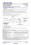
The image below shows the Option setting memory which consists of the option function select registers and 4 other
registers. These registers are divided into two groups located in flash-memory and are read on boot-up to determine
endianness, and also if peripherals like the Independent Watchdog Timer (IWDT), the High-speed On-chip Oscillator
(HOCO) and the Low Voltage Detection circuit (LVD0) are operational or not at boot time.
Figure 1: Option Function Select registers
Enabling the HOCO via these registers means that the HOCO is powered up and will start stabilizing immediately after
reset. This reduces the wait time when switching from the LOCO (the default clock source on startup) to the HOCO. If,
however, power savings is a requirement, then the registers can be configured to leave the HOCO off on power-up. The
OFS registers are also used to configure all the aspects of the IWDT operation.
4.1
Option Setting Memory Registers
Below is a summary of the Option Setting Memory registers. Make sure that they are configured properly before
startup.
OFS0 register
o Independent Watchdog Timer (IWDT) auto start
o IWDT timeout, frequency, windowing, interrupt type, and low power mode behavior
o Watchdog Timer (WDT) auto start
o WDT timeout, frequency, windowing, and interrupt type
OFS1 register
o LVD0 enable after reset
R01AN1657EU0111 Rev.1.11
Feb 3, 2014
Page 8 of 37
RX63N, RX631 Group
Quick Design Guide
o HOCO startup after reset
MDES/MDEB registers
o Big/little endian mode
UB Codes: In order to use the User Boot mode with a customer bootloader, it is necessary to configure the UB
codes. Refer to Section 7.3 in the hardware manual for details.
Below is an example on how to set the option setting memory register, MDES, which is at the address 0xFFFFFF80.
Note that unused/reserved bits are written to a ‘1’ as instructed in the Hardware Manual; be sure to set unused/reserved
bits per the hardware manual.
/* Allocate the name MDESreg to the address 0xFFFFFF80 */
#pragma address MDESreg = 0xFFFFFF80
#ifdef __BIG
/* Set as Big Endian */
const unsigned long MDESreg = 0xFFFFFFF8u
#else
/* Set as Little Endian */
const unsigned long MDESreg = 0xFFFFFFFFu
#endif
Most sample projects and demo code from Renesas includes code to set the option registers.
5.
Clock Circuits
The RX63N/RX631 group MCUs have five oscillators (see Table 4 - RX63X Oscillators). Four of these may be used
as the source for the main system clock; the remaining oscillator is dedicated to the Independent Watchdog Timer. In a
typical system, the main clock is driven with an external crystal or clock. This input is directed to the PLL where it is
multiplied up to the 104-200 MHz input range required by the PLL, and then post-divided down into the final system
clock speed which can have a maximum speed of 100 MHz.
Table 4 - RX63X Oscillators
Oscillator
Main clock
Input source
External crystal/resonator
Frequency
4 MHz to 16 MHz
-orExternal clock
External crystal/resonator
Up to 20 MHz
32 kHz
High-speed on-chip
(HOCO)
Low-speed on-chip
(LOCO)
On-chip oscillator
50 MHz
On-chip oscillator
125 kHz
Independent Watchdog
(IWDT)
On-chip oscillator
125 kHz
Sub-clock
5.1
Primary uses
PLL input, main system clock,
peripherals clocks, flash
clock, bus clock, SDRAM
clock, IEBUS clock, USB
clock, CAN clock
Real-time clock, system clock
in low power modes
Main system clock, peripheral
clocks in low power modes
System clock at startup, in low
power modes, & during main
oscillator stop detection
Independent watchdog timer
clock
Reset Conditions
After reset, RX63x MCU’s begin running with the low-speed on-chip oscillator (LOCO) as their main clock source.
The LOCO runs at 125 kHz which enables the part to start in a low-power state. Application code should switch to a
higher speed clock source as soon as is practical. Particular care should be taken to make sure that a faster clock source
is selected before the compiler startup code that initializes the C language runtime environment runs or else long startup
times may result. At reset, the main oscillator and the PLL are off by default. The HOCO and IWDT may be on or off
depending on the settings in the Option Setting Memory (see section 4).
R01AN1657EU0111 Rev.1.11
Feb 3, 2014
Page 9 of 37
RX63N, RX631 Group
5.2
Quick Design Guide
Clock Frequency Requirements
The ICLK must always be greater than or equal to the BCLK. Minimum and maximum frequencies are shown in the
table below.
Table 5.5 : Frequency Range for MCU Clocks
ICLK
PCLKA
PCLKB
PCLKC
PCLKD
Maximum Frequency [MHz]
100
100
50
100
50
Minimum Frequency [MHz]
1
1
2
1.
The ICLK and PCLKA frequencies must be the same and at least 12.5 MHz if the Ethernet controller is in use
2.
The PCLKB must run at a frequency of at least 24 MHz if the USB is in use.
FCLK
BCLK
UCLK
CANCLK
IECLK
Maximum Frequency [MHz]
50
100
48
20
50
Minimum Frequency [MHz]
1
2
48
1.
The FCLK must run at a frequency of at least 4 MHz when writing or erasing ROM or data flash.
2.
While BLCK can be set to 100 MHz, the maximum frequency that can be output on the BCLK pin is 50 MHz. A 50 MHz
clock can be output on the BCLK pin with a BCLK frequency of 100MHz by setting the BCLKDIV bit.
5.2.1
Requirements for USB Communications
The USB 2.0 Host/Function Module (USB) available on some members of the RX family requires a 48 MHz USB
clock signal (UCLK). UCLK is generated internally by dividing the PLL by either 3 or 4. The divider used depends on
the setting of the UCK bits in the SCKCR2 register. Additionally, the peripheral clock B (PCLKB) must be set to a
minimum of 24 MHz when USB is enabled.
5.2.2
Requirements for Ethernet Controller
When the Ethernet controller (EtherC) and Ethernet DMA Controller (E-DMAC) are used, PCLKA (Ethernet) must be
the same as ICLK, and both must be 12.5 MHz or greater.
5.2.3
Requirements for Programming and Erasing ROM or Data Flash
The FCLK must be at least 4MHz to perform programming and erasing on internal ROM and data flash.
5.2.4
Requirements for SDRAM Controller
When the SDCLK is used, BCLK cannot exceed 50 MHz.
5.3
Lowering CGC Power Consumption
The CGC area can account for 30%-40% of the power consumption of the chip. To aid in saving power, set the dividers
for any unused clocks (i.e. BCLK) to the highest possible value whenever possible. Also, if not using a clock then make
sure that it has been stopped by setting the appropriate register(s). The registers for controlling each clock source are
shown in the table below.
Table 5.6 : Clock Source Configuration Registers
Oscillator
Main clock
Sub-clock
High-speed on-chip (HOCO)
Low-speed on-chip (LOCO)
Independent Watchdog (IWDT)
R01AN1657EU0111 Rev.1.11
Feb 3, 2014
Register
MOSCCR
SOSCCR
HOCOCR
HOCOPCR
LOCOCR
ILOCOCR
Description
Starts/stops main clock oscillator
Starts/stops sub-clock oscillator
Starts/stops HOCO
Turns power on/off for HOCO
Starts/stops LOCO
Starts/stops IWDT on-chip oscillator
Page 10 of 37
RX63N, RX631 Group
5.4
Quick Design Guide
Writing the System Clock Control Register
Care should be taken when writing to the individual bit fields in the SCKCR register. The hardware manual states:
“To secure the processing after the clock frequency is changed, modify the pertinent clock control register to change the
frequency, and then read the value from the register, and then perform the subsequent processing..”
This means that every time a clock register is written, the user should read back the register and confirm the value has
been changed before making any more modifications to other clock registers. The easiest way to avoid this situation and
to ensure clock settings are correct is to write the entire register at once:
Unsafe
/*ICLK=96MHz*/
SYSTEM.SCKCR.BIT.ICK = 1;
/*PCLKA=96MHz*/
SYSTEM.SCKCR.BIT.PCKA = 1;
/*PCLKB=48MHz*/
SYSTEM.SCKCR.BIT.PCKB = 2;
/*FCLK=48MHz*/
SYSTEM.SCKCR.BIT.FCK = 2;
/*BCLK=48MHz*/
SYSTEM.SCKCR.BIT.BCK = 2;
5.5
Safe
/* ICLK=96MHz
PCLKA=96MHz
PCLKB=48MHz
FCLK=48MHz
BCLK=48MHz */
SYSTEM.SCKCR.LONG = (unsigned long)0x21021200;
Sample Code for Clock Setup
A separate application note covers software startup of the chip including setting the clocks for various applications. See
the “Initial Setting” application note in the References section of this document.
5.6
HOCO accuracy
The internal high-speed on-chip oscillator (HOCO) runs at 50 MHz +/-10% (refer to the Electrical Specifications in the
hardware manual for details.
5.7
FlashIF Clock
The FlashIF Clock (FCLK) is used as the operating clock for when programming and erasing internal flash (ROM and
DF) and for reading from the data flash. Therefore, the frequency setting of the FCLK will have a direct impact on the
amount of time it takes to read from the data flash. If the user’s program is reading from the data flash, or performing
programming or erasures on internal flash, then using the maximum FCLK frequency is recommended.
Please note that the FCLK frequency does not have any impact upon reading from ROM or reading and writing to RAM.
Both of these memory areas are always single-cycle access.
5.8
Board Design
Refer to the “Usage Notes” section of the Clock Generation Circuit chapter in the Hardware Manual for more
information on using the CGC and for board design recommendations. A separate application note, “RX63N/RX631
Groups Design Guide for Low CL Sub-Clock Circuits” (R01AN1187EJ0100), provides details on board layout for
clock circuits.
5.8.1
Important notes regarding the Oscillation Stop Detection Circuit
The Oscillation Stop Detection circuit is disabled by default after reset, but may be enabled by writing to the
OSTDE bit in the Oscillator Stop Detection Control Register (OSTDCR).
If oscillation stop detection is enabled and an oscillation stop is detected then the system clock will automatically
transition to the LOCO. The system clock will stay on the LOCO until the OSTDF flag in the OSTDSR register is
R01AN1657EU0111 Rev.1.11
Feb 3, 2014
Page 11 of 37
RX63N, RX631 Group
Quick Design Guide
cleared. In order to clear this flag the user must first change the CKSEL bits in the SCKCR3 register to choose the
LOCO. After the flag has been cleared the user can transition back to the main clock or PLL. These steps are
shown in the flow diagram from the hardware manual below.
When transitioning to the LOCO, the PLL multipliers and frequency dividers chosen in the SCKCR# and PLLCR#
registers are not changed.
Because the main clock oscillator is turned off in the Software Standby and Deep Software Standby low power
modes, the Oscillation Stop Detection circuit must be disabled before entering these modes.
The Oscillation Stop Detection circuit must be disabled before the main clock oscillator is stopped by setting the
MOSTP bit in the MOSCCR.
To use the Non-Maskable Interrupt for oscillator stop, the OSTEN bit in Non-Maskable Interrupt Enable Register
(NMIER) must be set.
Oscillation stop detection should only be enabled after the main clock has had proper settling time.
Application code servicing the Independent Watchdog Timer (IWDT) must take into account that the IWDT
continues to run at the same rate even though the MCU is running at a reduced rate.
The main clock provided to the RTC (RTCMCLK) is not transitioned to the LOCO. This means if the RTC has the
main clock selected as the count source and an oscillation stop occurs then the RTC will not count due to not
having a valid clock source.
R01AN1657EU0111 Rev.1.11
Feb 3, 2014
Page 12 of 37
RX63N, RX631 Group
6.
Quick Design Guide
Reset Requirements and the Reset Circuit
There are nine types of resets:
Reset Name
Pin reset
Power-on reset
Voltage-monitoring 0 reset
Voltage-monitoring 1 reset
Voltage-monitoring 2 reset
Deep software standby reset
Independent watchdog timer
reset
Watchdog timer reset
Software reset
6.1
Source
RES# is driven low
VCC rices (voltage detection: VPOR)
VCC falls (voltage detection Vdet0)
VCC falls (voltage detection Vdet1)
VCC falls (voltage detection Vdet2)
Deep software standby mode is canceled by an interrupt
The independent watchdog timer underflows, or a refresh
occurs
The watchdog timer underflows, or a refresh occurs
Register setting
Pin Reset
When the RES# pin is driven low, all processing is aborted and the RX enters a reset state. To reset the MCU while it is
running, RES# should be held low for the specified reset pulse width (minimum of 2 ms); RES# can be held low for a
shorter time during ROM or data flash programming and erasure (200 µsec) and about 1ms in Deep Software Standby,
Software Standby, and Low Speed-2 mode. Refer to the “Electrical Characteristics” chapter of the Hardware Manual
for more detailed timing requirements. Also refer to section 2, “Emulator Support” for details on reset circuitry in
relation to debug support.
There is no need to use an external capacitor on the RES# line because the POR circuit holds it low internally for a good
reset and a minimum reset pulse of 2 ms is required to initiate this process.
6.2
Power-On Reset
The Power On Reset occurs when the RES# pin is high as power is applied to the MCU. After VCC has exceeded the
power on voltage, Vpor (2.6V), and the power-on reset time, tPOR(4.6 ms) has elapsed, the chip is released from the
power-on reset state. The power-on reset time is a period that allows for stabilization of the external power supply and
the MCU.
Because the POR circuit relies on having RES# high concurrently with VCC, don’t place a capacitor on the reset pin.
This will slow the rise time of RES# in relation to VCC, preventing the POR circuit from properly recognizing the
power-on condition.
If the RES# pin is high when the power supply (VCC) falls to or below Vpor, a power-on reset is generated. The chip
is released from the power-on state after VCC has risen above Vpor and the tPOR has elapsed.
After a power on reset, the PORF bit in RSTSR0 is set to 1; following a pin reset PORF is cleared to 0.
6.3
Voltage-Monitoring Reset
The RX63N group includes circuitry that allows the MCU to protect against unsafe operation during brownouts. Onboard comparators check the supply voltage against three reference voltages, Vdet 0,Vdet1 and Vdet2. As the supply
dips below each reference voltage an interrupt or a reset can be generated. Vdet0 is fixed (~ 2.8V) but Vdet1 and
Vdet2 are configurable.
When Vcc subsequently rises above Vdet0, Vdet1 or Vdet2, release from the voltage-monitoring reset proceeds after a
stabilization time has elapsed.
Low Voltage Detection (Vdet1 and Vdet2) is disabled by default after reset; Vdet0 can be enabled out of reset by using
the Option Function register OFS1. For more details, see the chapter “Voltage Detection Circuit (LVD)” in the
hardware manual for details.
After an LVD Reset, the LVDnRF (n= 0, 1, 2) bit in RSTSR0 is set to 1
R01AN1657EU0111 Rev.1.11
Feb 3, 2014
Page 13 of 37
RX63N, RX631 Group
6.4
Quick Design Guide
Deep Software Standby Reset
This is an internal reset generated when deep software standby mode is canceled by an interrupt.
When deep software standby mode is canceled, a deep software standby reset is generated, and clock oscillation starts.
On receiving the interrupt, after the Deep Standby Cancellation Wait Time (tDSBY ~370 µsec) has elapsed, reset is
canceled and normal processing starts. For details of the deep software standby mode refer to the “Low Power
Consumption” chapter of the hardware manual.
After a Deep Software Standby Reset, the DPSRSTF bit in RSTSR0 is set to 1
6.5
Independent Watchdog Timer Reset
This is an internal reset generated by the Independent Watchdog Timer (IWDT).
When the IWDT underflows, an independent watchdog timer reset is optionally generated (NMI can be generated
instead) and the UNDFF bit in the IWDTSR is set to a 1. After a short delay (960 µsec), the IWDT reset is canceled.
6.6
Watchdog Timer Reset
This is an internal reset generated by the Watchdog Timer (WDT).
When the WDT overflows, a watchdog timer reset is optionally generated (NMI can be generated instead), and the
WDTRF bit in RSTSR2 is set to a 1. After a short delay (960 µsec) the WDT reset is canceled.
6.7
Software Reset
This is an internal reset generated by writing 0xA501 to the SWRR register. The internal reset time when using
software reset is a maximum of 960 µsec. When using software reset, make sure that the watchdogs are serviced first
before issuing the software reset command.
6.8
Determining the Reset Source
The RX63N allows the user to determine the reset signal generation source. Refer to the hardware manual section 6.3.9
Determination of Reset Generation Source for the flow diagram.
The following code sample shows how to determine the source that caused a reset.
R01AN1657EU0111 Rev.1.11
Feb 3, 2014
Page 14 of 37
RX63N, RX631 Group
#define
#define
#define
#define
#define
#define
#define
#define
#define
RST_SRC_SW
RST_SRC_DSSTDBY
RST_SRC_VDET2
RST_SRC_VDET1
RST_SRC_WDT
RST_SRC_IWDT
RST_SRC_VDET0
RST_SRC_POR
RST_SRC_PIN
Quick Design Guide
0x001
0x002
0x004
0x008
0x010
0x020
0x040
0x080
0x100
/*
/*
/*
/*
/*
/*
/*
/*
/*
Software reset */
Deep software standby reset */
Voltage monitor 2 reset */
Voltage monitor 1 reset */
Watchdog timer reset */
Independent watchdog reset */
Voltage monitor 0 reset */
Power on reset */
Pin reset */
int ResetSource ()
{
/* Check for software reset */
if (SYSTEM.RSTSR2.BIT.SWRF == 1) return (RST_SRC_SW) ;
/* Check for deep software standby reset */
if (SYSTEM.RSTSR0.BIT.DPSRSTF == 1) return (RST_SRC_DSSTDBY) ;
/* Check for voltage monitoring reset on Vdet2 */
if (SYSTEM.RSTSR0.BIT.LVD2RF == 1) return (RST_SRC_VDET2) ;
/* Check for voltage monitoring reset on Vdet1 */
if (SYSTEM.RSTSR0.BIT.LVD1RF == 1) return (RST_SRC_VDET1) ;
/* Check for watchdog timer (WDT) reset */
if (SYSTEM.RSTSR2.BIT.WDTRF == 1) return (RST_SRC_WDT) ;
/* Check for independent watchdog timer (IWDT) reset */
if (SYSTEM.RSTSR2.BIT.IWDTRF == 1) return (RST_SRC_IWDT) ;
/* Check for voltage monitoring reset on Vdet0 */
if (SYSTEM.RSTSR0.BIT.LVD0RF == 1) return (RST_SRC_VDET0) ;
/* Check for power on reset */
if (SYSTEM.RSTSR0.BIT.PORF == 1) return (RST_SRC_POR) ;
/* If no other reset sources were indicated, then it must have been a pin reset */
return (RST_SRC_PIN) ;
}
R01AN1657EU0111 Rev.1.11
Feb 3, 2014
Page 15 of 37
RX63N, RX631 Group
7.
Quick Design Guide
Memory
The RX600 Series of MCU’s have a 32-bit memory space spanning 4 Gbyte that includes areas for on-chip memory and
peripherals. Some members of the family include a 256 Mbyte region that allows access to devices connected to
external memory buses. Program and data memory share the address space; separate buses are used to access each,
increasing performance and allowing same-cycle access of program and data. Contained within the memory map are
regions for on-chip RAM, peripheral I/O registers, program ROM and data flash, and external memory.
Address
Memory Map
0x0000 0000
RAM
(up to 128K)
0x0002 0000
Reserved
0x0008 0000
Peripheral I/O Registers
0x0010 0000
0x0010 8000
0x0100 0000
0x0800 0000
On-chip data flash
(up to 32K)
Part-specific memory
(see data sheet)
External Address Space
(CS Area - 112 Mbyte)
External Address Space
(SDRAM Area - 128 Mbyte)
0x1000 0000
Reserved
0xFF00 0000
Reserved
0xFFE0 0000
0xFFFF FFFF
7.1
On-Chip ROM
(up to 2 Mbytes)
External Address Space
In On-Chip ROM Disabled
Extended Mode
(16 Mbyte)
On-Chip RAM
Members of the RX family include high-speed on-chip RAM that can be accessed in a single cycle at CPU speeds up to
100 MHz. Data stored in RAM is retained in all low-power modes of the CPU; the entire RAM or a portion of it may
be powered down during Deep Software Standby Mode to further reduce power consumption. Depending on the RX
device, up to 128K of on-chip RAM is accessed starting at address 0x00000000.
7.2
Peripheral I/O Registers
Blocks of peripheral I/O registers appear at various locations in the memory map depending on the device and the
current operating mode. The majority of peripheral I/O registers occupy a region from address 0x00080000 to
0x00100000. This region contains registers that are available at all times in all modes of operation. Other blocks of
peripheral registers, such as those to control access flash memory, vary in location and size by device; consult the
hardware manual for specifics. The Renesas tool chain generates C header files that map all of the peripheral I/O
registers for a specific device to easily accessible C data structures.
7.3
Program ROM & Data Flash
The RX600 Series of MCUs feature two flash memory sections: program ROM and data flash. The program ROM is
designed to store user application code and constant data. The data flash is designed to store information that may be
updated from time to time such as configuration parameters, user settings, or logged data. The units of programming
and erasure in the data flash area are much smaller than that of the program ROM (2 bytes for Data Flash versus 128
R01AN1657EU0111 Rev.1.11
Feb 3, 2014
Page 16 of 37
RX63N, RX631 Group
Quick Design Guide
bytes for ROM). This makes the data flash more suited for storing information that would benefit from the finer
granularity of the data flash area, such as configuration parameters.
Both the data flash and ROM areas can be programmed or erased by application code. This enables field firmware
updates without having to connect an external programming tool. To speed development of code that supports inapplication programming of the flash, Renesas supplies a “Simple Flash API for RX” application note that includes
sample code. This application note can be found on the Renesas web site; see chapter 15 - References.
One some RX600 Series MCUs another flash area is available to the user. This small flash area can be used along with
User Boot Mode to hold a custom bootloader that the user designs. This area cannot be erased or programmed during
normal user application execution which makes it ideal for storing a bootloader.
7.3.1
Enabling Data Flash Memory
Out of reset the data flash memory cannot be read, programmed, or erased. In order to allow these accesses the data
flash must be enabled. There are two sets of registers in the data flash that enable these types of accesses. The first are
the E2 Data Flash Read Enable Registers (DFLRE#) which enable read capabilities on individual data flash blocks. The
second are the E2 Data Flash P/E Enable Registers (DFLWE#) which allow programming and erasing operations on
individual data flash blocks. Both sets of registers are 16-bits wide and require a key to be written along with the
desired settings.
7.3.2
Blank Checking of Data Flash Memory
Data flash locations on the RX cannot be checked for blank (i.e. erased) by comparing the read value to 0xFF. The
reason for this is that RX data flash cells actually have 2 cells per bit (compared to 1 cell per bit for ROM). This means
that there are 4 different states the bit can be in; though only 3 are used: undefined, 0, and 1. Erased data flash locations
on the RX have a value of undefined (not 0 or 1) and therefore the read bit value cannot be used to determine if the bit
is erased. When a data flash bit is programmed, one of the cells is always changed depending on whether a 0 or 1 is
being written. If the user wishes to know if a data flash location is erased then they should use the blank check
command in the Flash Control Unit. The “Simple Flash API for RX Application Note” also includes an API function
that serves this purpose.
7.3.3
Background Operation
RX600 MCUs support background operations for ROM and data flash. This means that when a program or erase is
started, the user can keep executing and accessing memory from memory areas other than the one being operated on.
For example, the CPU can execute application code from ROM while the data flash memory is being erased or
programmed. Also, the CPU can execute application code from RAM while the ROM memory is being erased or
programmed. The only exception to this rule is that the data flash cannot be accessed during ROM programming or
erasing.
7.3.4
Data Flash in Low-Speed Operating Mode 2
The data flash cannot be accessed when the MCU is in low-speed operating mode 2. If the MCU transitions into another
operating mode then the data flash can be accessed normally.
7.3.5
ID Code Protection
RX600 MCUs have a 32-byte memory area that is used as an ID code. If this ID code is left blank (0xFF’s) then no
protection is enabled and access to the MCU is allowed through boot mode or using the on-chip debugger. If the ID
code is set then the user can control access to these modes. The user can choose to always disallow connections, or can
choose to allow connections when a matching ID code is input. Refer to the “ID Code Protection (Boot Mode)” and “ID
Code Protection on Connection of the On-Chip Debugger” sections of the hardware manual for more information.
7.3.6
Parallel Programmer Protection
RX600s MCU have the ability to limit what operations parallel ROM programmers can perform on the MCU. The
choices include allowing both reading and writing, prohibiting writing, and prohibiting writing and reading. Which
option is chosen is performed by setting a constant value at specified memory address. See ‘ROM Code Protection’ in
the hardware manual for more details.
7.4
External Memory & Chip Selects
Some members of the RX family include an external data bus for connection to external memory and devices. Some
members also include a built-in SDRAM controller that allows the use of up to 128 Mbytes of external SDRAM. Eight
programmable chip selects provide a number of options that are settable on a per-chip select basis to allow connection
to a wide range of external devices. The external chip select area of the memory map begins at address 0x0100 0000.
Consult the hardware manual for details.
R01AN1657EU0111 Rev.1.11
Feb 3, 2014
Page 17 of 37
RX63N, RX631 Group
Quick Design Guide
The external memory bus is off by default and must be enabled through writing to a number of registers. The
SYSCR0.EXBE bit must be set (see chapter 3 of the HW manual), followed by the setting the pin functions in the
Multi-Function Pin Controller (chapter 22 of the HW manual), and then registers that control the external bus (chapter
16 of the HW manual. Review these chapters carefully as there are specific constraints on how to write the registers.
7.4.1
Special note about CS0
Chip select zero is mapped in memory to the same space as the internal ROM of the device. When using chip select
zero, the device boots out of internal ROM. Application code must then enable CS0 and disable on-chip ROM. The
ROM is disabled by clearing the SYSCR0.ROME bit (see chapter 3 of the HW manual). When disabling on-chip ROM,
the on-chip data flash is also disabled. Once on-chip ROM is disabled it cannot be re-enabled without resetting the chip.
Users are advised not to use chip select zero unless they have very specific reasons for doing so.
7.4.2
Using External 16-bit Memory Devices
When connecting an external 16-bit memory device that has a byte select line, connect A1 of the MCU to A0 of the
memory and A0 of the MCU to the byte select line.
7.5
Memory Access Speed
Both the RAM and internal ROM can be accessed in a single cycle with no wait states. This is true to up to the current
maximum operating frequency of the RX600 Series, which is 100MHz. The system peripheral clock limits speed when
accessing peripheral I/O registers. An example: if the clocks are set at their maximums (System clock: 100MHz,
Peripheral Clock B: 50MHz), it will take 2 CPU cycles to access a peripheral I/O register. Accesses to the data flash
are controlled by the FlashIF Clock (FCLK). The data flash memory takes 6 cycles of the FCLK to read 1 or 2 bytes.
7.6
Data Alignment
There are no limits for aligning data. The MCU is capable of doing byte, word, and long accesses on odd memory
locations. While it is still optimal to align data accesses, it is not required.
R01AN1657EU0111 Rev.1.11
Feb 3, 2014
Page 18 of 37
RX63N, RX631 Group
8.
Quick Design Guide
Register Write Protection
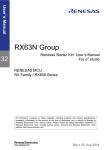
The Register Write Protection function protects certain registers in the MCU from inadvertent changes. The system
Protect Register (PRCR) contains bits that enable writing to other registers in the MCU. PRCR is a sixteen bit register
with a key in the upper byte and the protection bits in the lower byte. A key code of A5 hex must be written to the
upper 8 bits of PRCR to modify any of the lock bits in the lower byte. Setting a PRC bit to a 1 allows writing of the
protect registers. Protection is enabled by default after reset (all PRC bits are zero after reset).
Figure 2 - PRCR Register
b15
b14
b13
b12
b11
b10
b9
b8
PRKEY[7:0]
b7
b6
b5
b4
b3
b2
—
—
—
—
PRC3
—
b1
b0
PRC1 PRC0
Table 7 - PRCR Protection Bits
PRCR bit
PRC0
PRC1
PRC3
PRKEY[7:0]
8.1
Description
Registers in the Clock Generation Circuit (CGC) that control operation of
the MCU’s clocks: SCKCR, SCKCR2, SCKCR3, PLLCR, PLLCR2, BCKCR,
MOSCCR, SOSCCR, LOCOCR, ILOCOCR, HOCOCR, OSTDCR, OSTDSR
Registers related to the operating modes: SYSCR0, SYSCR1
Registers related to the low power consumption functions: SBYCR,
MSTPCRA, MSTPCRB, MSTPCRC, OPCCR, RSTCKCR, MOSCWTCR,
SOSCWTCR, PLLWTCR, DPSBYCR, DPSIER0 to DPSIER3, DPSIFR0 to
DPSIFR3, DPSIEGR0 to DPSIEGR3
Registers related to clock generation circuit: MOFCR, HOCOPCR
Software reset register: SWRR
Registers related to the Low Voltage Detection circuit (LVD): LVCMPCR,
LVDLVLR, LVD1CR0, LVD1CR1, LVD1SR, LVD2CR0, LVD2CR1, LVD2SR
Write 0xA5 to these bits to allow writing to the PRC bits. To modify the
system protection, write 0xA5 to the PRKEY bits while setting the PRC bits.
System Protection Example code
To unlock all registers, write 0xA50B to the PRCR. Set it back to 0xA500 to protect them all again.
/* Disable write protection for all protected registers */
SYSTEM.PRCR.WORD = 0xA50B;
/* Change system clock divisors */
SYSTEM.SCKCR.LONG = 0x21031222 ;
/* Turn write protection back on for all protected registers */
SYSTEM.PRCR.WORD = 0xA500;
R01AN1657EU0111 Rev.1.11
Feb 3, 2014
Page 19 of 37
RX63N, RX631 Group
9.
Quick Design Guide
I/O Ports and Register Structures
Renesas supplies a C language header file named ‘iodefine.h’ that allows users to easily access I/O registers through
unions and structures. The syntax of using these unions and structures to access hardware registers is:
Peripheral.Register<.AccessWidth>.<Bit>
Where:
Peripheral is the name of a specific peripheral such as: SCI0, ICU, AD0, etc.
Register is the register abbreviation for a specific register such as: SCR, IPR, ADCR, etc.
AccessWidth is an optional field used when an I/O register has more than one field. One of four keywords
specifies how to access the register: LONG, WORD, BYTE, or BIT.
Bit is an optional field that is only used when AccessWidth is BIT. It specifies the name of a single bit or range
of bits in a register such as: TIE, IPR, or MODE.
Note that Peripheral, Register, and Bit match the mnemonics used in the RX Hardware Manual.
If accessing a register that does not have bit fields, use the peripheral and register name only. An example is ‘MTU0
Timer Counter’ shown in the table below.
What to access
Bits to Access
How to access
System Clock Control Register (SCKCR)
32
SYSTEM.SCKCR.LONG
MTU0 Timer Counter
16
MTU0.TCNT
SCI Channel 3, Receive Data Register (RDR)
8
SCI3.RDR
SCI Channel 3, Serial Control Register (SCR)
8
SCI3.SCR.BYTE
SCI Channel 3, Receive enable bit in SCR
1
SCI3.SCR.BIT.RE
Port 2, Pin 5, Port Direction Register Bit
1
PORT2.PDR.BIT.B5
Counter Clear bit field in TMR0 TCR register
2
TMR0.TCR.BIT.CCLR
CMT0 Compare Match Timer Control Register
16
CMT0.CMCR.WORD
9.1
I/O Register Macros
New macros in the iodefine.h for RX family parts make it easier to refer to ICU control registers, module stop registers,
DTC enable registers, and interrupt vector numbers by the logical names associated with the peripherals. These macros
allow portability across RX family members by hiding specific register and vector numbers. See the documentation
contained in iodefine.h and sections below for details.
Some examples:
Macro
IR(“module name”, “bit name”)
Usage example
if ( IR(SCI0,TXI0) == 1)…
IEN(“module name”, “bit name”)
IEN(SCI0,TXI0) = 1 ;
IPR(“module name”, “bit name”)
IPR(SCI0,TXI0) = 0x02 ;
MSTP(“module name”)
MSTP(SCI0) = 0 ;
VECT(“module name”, “bit name”)
#pragma interrupt
(MySciTxIsr(vect=VECT(SCI0,TXI0))
R01AN1657EU0111 Rev.1.11
Feb 3, 2014
Page 20 of 37
RX63N, RX631 Group
9.1.1
Quick Design Guide
ICU Register Macros
These macros help with accesses to the following registers in the ICU:
Interrupt Request Registers (IRn)
DTC Activation Enable Register (DTCERn)
Interrupt Request Enable Register (IERm)
Interrupt Priority Register (IPRm)
Instead of having to refer to the values for ‘n’ and ‘m’, the user can specify the desired peripheral and interrupt.
Application code then becomes portable across members of the RX family that share the same peripheral.
Examples are below.
Without Macro
With Macro
ICU.IR[176].BIT.IR = 0;
IR(TMR2, CMIA2) = 0;
ICU.DTCER[176].BIT.DTCE = 1;
DTCE(TMR2, CMIA2) = 1;
ICU.IER[0x16].BIT.IEN0 = 1;
IEN(TMR2, CMIA2) = 1;
ICU.IPR[176].BIT.IPR = 3;
IPR(TMR2, CMIA2) = 3;
9.1.2
Vector Number Macro
When using the Renesas compiler, interrupt service routines written in C language are hooked to specific interrupts
vectors using the #pragma interrupt directive:
#pragma interrupt (INT_RXI0(vect=214))
void INT_RXI0 (void) ;
The above example hooks the C language function “INT_RXI0” to interrupt vector number 214, which is the receive
interrupt for SCI0. This same interrupt source (RXI0) may not use the same vector number (214) on other members of
the RX family. To provide portability, the VECT() macro allows the user to specify a logical name for an interrupt
source which is then expanded by a part-specific iodefine.h file to the correct vector number.
The syntax is:
VECT(Peripheral, Source)
Where:
Peripheral is the name of a specific peripheral such as: SCI0, TMR2, AD0, etc.
Source is the name of an interrupt source in that peripheral such as: RXI0, CMIA2, ADI0, etc.
Example:
Without Macro
/* Declare ISR for TMR2 – CMIA2 */
#pragma interrupt TMR2_CMIA2(vect=176)
With Macro
/* Declare ISR for TMR2 – CMIA2 */
#pragma interrupt TMR2_CMIA2(vect=VECT(TMR2,CMIA2))
R01AN1657EU0111 Rev.1.11
Feb 3, 2014
Page 21 of 37
RX63N, RX631 Group
9.1.3
Quick Design Guide
Module Stop Control Macro
The Module Stop Control Registers allow individual peripherals to be turned on or off for power savings. By default,
most peripherals are off at power up and must be powered on before accessing their control registers (see hardware
manual for details). The Module Stop Control Registers contain bit fields for a number of peripherals; these registers
change in layout from part to part in the RX family. The MSTP( ) macro simplifies control of the stop state of
peripherals and makes code portable.
To use this macro, specify the name of the peripheral:
MSTP (Peripheral)
Example:
Without Macro
With Macro
/* Turn on TMR2 */
/* Turn on TMR2 */
SYSTEM.MSTPCRA.BIT.MSTPA4 = 0;
MSTP(TMR2) = 0;
Care should be taken when using the MSTP() macro because sometimes multiple peripheral channels will map to the
same MSTP bit. For example, the MSTPA15 bit controls CMT0 and CMT1 (both channels are part of CMT unit 0).
This means that both MSTP(CMT0) and MSTP(CMT1) will resolve to SYSTEM.MSTPCRA.BIT.MSTPA15. This is
not a problem when powering on a peripheral but could cause a problem when powering down. If the user turns off
CMT0 to save power by using ‘MSTP(CMT0) = 1;’ then they will also turn off CMT1 even if they did not intend to.
The user can avoid this problem by always checking to make sure both channels are not in use before powering down.
9.2
I/O Registers and Endian Settings
The RX I/O Registers are at fixed locations and byte orders in memory regardless of the endian setting of the processor.
When accessing data memory, the most significant byte of a 16-bit word can be stored at either an odd or even address
depending on the endian setting; this is not the case with the RX I/O Registers.
Always access I/O registers using the proper access instruction for the size of the register; do not access word or
long word registers with byte instructions, or long word registers with word instructions. Do not assume that
registers for a particular peripheral are big-endian or little-endian.
This can confuse some compilers depending on the data structures used to access I/O Registers, particularly when using
bit fields in 16-bit or wider registers. The iodefine.h file generated by the Renesas tools uses directives specific to the
Renesas compiler (such as “__evenaccess”) to ensure that access to the I/O registers is correct regardless of the endian
setting of the processors.
Because of this:
The user is strongly advised to use only the structures in iodefine.h file to access I/O registers
and
to check the compiler output at the assembly language level if changes are made to the file.
R01AN1657EU0111 Rev.1.11
Feb 3, 2014
Page 22 of 37
RX63N, RX631 Group
Quick Design Guide
10. I/O Port Configuration and the Multifunction Pin Controller (MPC)
The I/O Ports and MPC sections of the Hardware Manual describe exact pin configurations based on peripheral
selection and other register settings. Some general information is listed below.
10.1
Setting Up and Using Port as GPIO
Select a pin as an output by writing a “1” to the corresponding Port Direction Register (PDR)
The Port Direction Register (PDR) is read/write. Setting the value to a “1” selects the pin as an output. Default
state for I/O Ports is “0” (input). The port direction registers can be read on the RX.
The Port Output Data Register (PODR) is read/write. When the PODR is read the state of the output data latch
(not the pin level) is read.
The Port Input Register (PIDR) is read only. Read the PIDR register to read the pin state.
The Port Mode Register (PMR) is read/write and is used to specify whether individual pins function as GPIO
or as peripheral pins. Out of reset all PMR registers are set to 0 which sets all pins to work as GPIO. If a PMR
register is set to 1 then that corresponding pin will be used for peripheral functions. The peripheral function is
defined by that pin’s MPC setting.
When setting a pin as an output it is recommended that the desired output value of the port be written to the
data latch first, then the direction register is set to an output. Though not important in all systems, this prevents
an unintended output glitch on the port being setup.
Examples:
Set up Port 0, bit 1 as an input:
/* Make pin an input */
PORT0.PDR.BIT.B1 = 0;
/* See if input is high */
if (PORT0.PIDR.BIT.B1 == 1) …
Set up Port 0, bit 1 as an output:
/* Set the output level first to prevent glitches */
PORT0.PODR.BIT.B1 = 1;
/* Make pin an output */
PORT0.PDR.BIT.B1 = 1;
10.1.1
Internal Pull-Ups
Each pin on ports 0 through 9, A through G, and J has the option of enabling a pull-up resistor. The pull-up is
controlled by the Pull-Up Resistor Control Register (PCR). Each bit in the PCR register controls the
corresponding pin on the port. Set the PCR bit to “1” to enable the pull-up and to “0” to disable it.
Out of reset all PCR registers are cleared to 0 therefore all pull-up resistors are disabled.
The pull-up is automatically turned off whenever a pin is designated as an external bus pin, a GPIO output, or
a peripheral function output pin.
10.1.2
Open-Drain Output
Pins configured as outputs normally operate as CMOS outputs.
Each pin on ports 0 through 9, A through G, and J has the option being configured as a NMOS open-drain
output.
The Open Drain Control Registers (ODR0 & ODR1) control which pins operate in open-drain mode. The
ODR0 registers control the settings for pins 0 through 3 on each port. The ODR1 registers control the settings
R01AN1657EU0111 Rev.1.11
Feb 3, 2014
Page 23 of 37
RX63N, RX631 Group
Quick Design Guide
for pins 4 through 7 on each port. Setting the applicable bit in each register to a “1” makes the output opendrain.
10.1.3
Because of parasitic diodes on the RX port pins, maximum voltage to open drain outputs must be limited to
VCC.
Drive Capacity
Each pin on ports 0, 2, 5, 9, A to E, and G has the option of enabling high-drive output. Whether normal or
high drive is enabled is controlled by the Drive Capacity Control Registers (DSCR).
Out of reset all DSCR registers are cleared to 0 therefore all pins are set to normal drive output. Setting “1” to
a DSCR bit will enable high-drive output for the selected pin.
The maximum total output of all pins summed together is 80mA.
The differences between normal and high drive are shown below:
Drive Capacity
Max (mA)
Permissible output current per pin (average)
Normal Drive
2.0
Permissible output current per pin (average)
High Drive
3.8
Permissible output current per pin (maximum)
Normal Drive
4.0
Permissible output current per pin (maximum)
High Drive
7.6
10.2
Setting Up and Using Port Peripheral Functions
The Multi-Function Pin Controller (MPC) is a new feature on the RX63x that replaces the Port Function Control
registers on the RX62x. The result is a much more flexible assignment of pins to peripherals functions, with a much
finer granularity of selection.
Since many pins have multiple functions the RX63N/RX631 Group has Pin Function Control Registers
(PmnPFS where m = port, n = pin) that allow you to change the function assigned to a pin.
Each pin has its own PmnPFS register. For example, the P10PFS register allows you to choose whether you
want port 1 pin 0 to be assigned to the MTU or TMR peripheral.
Each PmnPFS register allows a pin to be used for peripheral function (PSEL bits), as an IRQ input pin (ISEL
bit), or as an analog input pin (ASEL bit). If the ASEL bit is set to “1” (use pin as analog input pin) then the
pin’s PMR bit should be set for GPIO use and the pin’s PDR bit should be set for input.
Refer to the appropriate register under Multi-Function Pin Controller (MPC) >> Register Descriptions in the
HW manual for a table of the available peripheral functions for each pin.
In order to ensure that no unexpected edges are input or output on peripheral pins make sure to clear the PMR
bit for the targeted pin before modifying the pin’s PmnPFS register.
All PmnPFS registers are write protected out of reset. In order to write to these registers the Write-Protect
Register (PWPR) must first be used to enable writing.
Care should be taken when setting PmnPFS registers such that a single function is not assigned to multiple pins.
The user should not do this but the MCU will allow it. If this occurs the function on the pins will be undefined.
If you are using the external bus, the Ethernet controller, or USB, there are additional registers in the MPC that
must be configured before using these peripherals.
The example below shows the steps for setting port 0, bit 1 to be a SCI receiver input pin (RXD6). These steps
are defined in the Multi-Function Pin Controller (MPC) >> Usage Notes >> Procedure for Specifying
Input/Output Pin Function section of the RX63N HW manual.
R01AN1657EU0111 Rev.1.11
Feb 3, 2014
Page 24 of 37
RX63N, RX631 Group
Quick Design Guide
Example - Enabling SCI6 to use port 0, bit 1 as SCI receiver input pin
/* Allow writing to MSTP registers. */
SYSTEM.PRCR.WORD = 0xA50B;
/* Enable SCI6 (take out of stop mode) */
MSTP(SCI6) = 0;
/* Configure SCI6. */
...
/* Clear PMR bit for P0_1 before changing P01PFS register. */
PORT0.PMR.BIT.B1 = 0;
/* Set P0_1 as input pin. */
PORT0.PDR.BIT.B1 = 0;
/* Unlock protection register */
MPC.PWPR.BIT.B0WI = 0;
/* Unlock MPC registers */
MPC.PWPR.BIT.PFSWE = 1;
/* Set P0_1 to be used for RXD6 function. */
MPC.P01PFS.BYTE = 0x0A;
/* Assign P0_1 to be used for peripheral function. */
PORT0.PMR.BIT.B1 = 1;
/* Set other port registers and re-enable MPC & MSTP register protection. */
10.3
Setting Up and Using IRQ Pins
Certain port pins can be used as hardware interrupt lines (IRQ). See the Multi-Function Pin Controller (MPC)
>> Overview section of the HW Manual for information on which pins are available for your MCU. When
looking through the list of available IRQ pins you will notice that some have a “-DS” postfix (e.g. IRQ1-DS).
The “-DS” designates that this pin can be used to wake the MCU out of deep software standby mode.
To set a port pin to be used as an IRQ pin, the Interrupt Input Function Select bit (ISEL) in the pin’s PFS
register must be set to “1”.
Pins can be used for both IRQ and peripheral functions simultaneously. To enable this the user should set both
the ISEL and PSEL bits in the pin’s PFS register.
IRQ pins can trigger interrupts on detection of:
o
Low level
o
Falling edge
o
Rising edge
o
Rising and falling edges
Which trigger is selected is chosen using the IRQ Control Registers (IRQCRi).
Digital filtering is available for IRQ pins. The filters are based on repetitive sampling of the signal at one of
four selectable clock rates (PCLK, PCLK/8, PCLK/32, PCLK/64). They filter out short pulses: any high or
low pulse less than 3 samples at the filter rate. The filters are useful for filtering out ringing and noise in these
lines, but are much too quick for filtering out long events like mechanical switch bounce. Enabling filtering
adds a short bit of latency (the filter time) to the hardware IRQ lines.
Digital filtering can be enabled for each IRQ pin independently. This is done by setting the IRQ Pin Digital
Filter Enable Registers (IRQFLTEi).
The clock rate for digital filtering is configurable for each IRQ pin independently. This is done by setting the
IRQ Pin Digital Filter Setting Registers (IRQFLTCi).
The example below shows code to enable IRQ8 with falling edge detection on port 4, pin 0.
R01AN1657EU0111 Rev.1.11
Feb 3, 2014
Page 25 of 37
RX63N, RX631 Group
Quick Design Guide
Example - Enabling port 4, bit 0 as IRQ8 input
/* P4_0 is not being used for peripheral function. */
PORT4.PMR.BIT.B0 = 0;
/* Make pin an input */
PORT4.PDR.BIT.B0 = 0;
/* Unlock protection register */
MPC.PWPR.BIT.B0WI = 0;
/* Unlock MPC registers */
MPC.PWPR.BIT.PFSWE = 1;
/* Set P4_0 to be used for IRQ8 function. */
MPC.P40PFS.BYTE = 0x40;
/* Set IRQ type (falling edge) */
ICU.IRQCR[8].BIT.IRQMD = 0x01;
/* Clear any pending interrupts. */
IR(ICU,IRQ8) = 0;
/* Set interrupt priority to 3 */
IPR(ICU,IRQ8) = 0x03;
/* Enable the interrupt */
IEN(ICU,IRQ8) = 1;
/* Be sure to write an interrupt handler!!! */
10.4
Unused Pins
NOTE:
Some pins require specific termination: See the “I/O Ports: Handling
of Unused Pins” section of the Hardware Manual for specific
recommendations.
Unused pins that are left floating can consume extra power and leave the system more susceptible to noise problems.
Terminate unused pins with one of the methods detailed here:
1.
The first option is to set the pin to an input (the default state after Reset) and connect the pin to Vcc or Vss using a
resistor. There is no difference from a MCU standpoint between one connection or another; however, there may be
an advantage from a system noise perspective. Vss is probably the most typical choice. Avoid connecting a pin
directly to Vcc or Vss since an accidental write to the port’s direction register that sets the pin to an output could
create a shorted output.
2.
A second method is to set the pin to an output. It does not matter whether the pin level is set high or low; however,
setting the pin as an output and making the output low connects the pin internally to the ground plane. This may
help with overall system noise concerns. A disadvantage of setting unused pins to outputs is that the configuration
of the port must be done via software control. While the MCU is held in Reset and until the direction register is set
for output the pin will be a floating input and may draw extra current. If the extra current can be tolerated during
this time, this method eliminates the external resistors required in the first method.
3.
A variation on leaving the pins as inputs and terminating them with external resistors uses the internal pull-ups
available on some ports of the MCU. This has the same limitation as setting the pins to outputs (requires the
program to set up the port) but it does limit the effect of accidental pin shorts to ground, adjacent pins or Vcc since
the device will not be driving the pin.
10.5
Nonexistent Pins
When using a MCU with less than 177 or 176 pins, set the corresponding bits of nonexistent ports in the PDR register to
“1” (output) and in the PODR register to “0”. The user can see which ports are available on each MCU package by
reviewing the “Specifications of I/O Ports” table in the I/O Ports section of the HW Manual. For example pins 0 and 1
on port 1 are only available on 177 and 176 pin packages. A separate application note covers software startup of the
chip including initialization of nonexistent pins. See the “Initial Setting” application note in the References section of
this document.
R01AN1657EU0111 Rev.1.11
Feb 3, 2014
Page 26 of 37
RX63N, RX631 Group
10.6
Quick Design Guide
Electrical Characteristics
GPIO require CMOS level inputs (High ≥0.8 * Vcc, Low≤ 0.2*Vcc) see electrical characteristics for more information
10.7
MPC Register Setting Summary
The following table can be found in section 22.4 of the Hardware Manual. Additional information can be found there.
PmnPFS
Item
PMR.Bn
PDR.Bn
ASEL
ISEL
PSEL[4:0]
Point to note
After a reset
0
0
0
0
00000b
Pins function as general input port
pins after release from the reset
state.
General input ports
0
0
0
0/1
X
Set the PmnPFS.ISEL bit to 1 if
these are multiplexed with interrupt
inputs.
General output ports
0
1
0
0
X
Peripheral functions
1
X
0
0/1
Peripheral
function
setting
Interrupt inputs
0
0
0
1
X
NMI
X
X
X
X*
X
Register settings are not required
Analog inputs and
outputs
0
0
1
X*
X
Set these as general input port pins
so that the output buffers are turned
off
Time-capture eventinput pins
0
0
X
0/1
X
Set these as general input port pins
so that the output buffers are turned
off.
External bus
0
X
0
0
X
Set the PMR.Bn bit and the
PmnPFS.ISEL bit to 0 and switch
the input buffers off
JTAG-IF
0
X
X
0
X
Set the PMR.Bn bit and the
PmnPFS.ISEL bit to 0 and switch
the input buffers off
FINE interface
0
X
X
0
X
Set the PMR.Bn bit and the
PmnPFS.ISEL bit to 0 and switch
the input buffers off
EXTAL/XTAL
0
0
X
X*
X
Set these as general input port pins
so that the output buffers are turned
off
XCIN/XCOUT
0
0
X
X*
X
Set these as general input port pins
so that the output buffers are turned
off.
Set the PmnPFS.ISEL bit to 1 if
these are multiplexed with interrupt
inputs.
X: setting not required
0/1:
Setting the PmnPFS.ISEL bit to 0 makes the pin incapable of functioning as an IRQ pin.
Setting the PmnPFS.ISEL bit to 1 makes the pin capable of functioning as an IRQ pin
*Even if the PmnPFS.ISEL bit is set to 1, the pin will not function as an IRQn input pin.
R01AN1657EU0111 Rev.1.11
Feb 3, 2014
Page 27 of 37
RX63N, RX631 Group
Quick Design Guide
11. Module Stop Function
To maximize power efficiency, the RX family of MCU’s allow on-chip peripherals to be shut down individually by
writing to the Module Stop Control Registers (MSTPCRi, i=A, B, C). After reset most of the modules are stopped
(exceptions are DMAC, EXDMAC, DTC, and on-chip RAM; see hardware manual for details).
Before accessing any of the registers for a peripheral, it must be enabled by taking out of stop mode by writing a ‘0’ to
the corresponding bit in the MSTPCRi register. The MSTPCRi registers are protected registers and they have to be
unprotected by writing to the PRCR registers first (see section 8 - Register Write Protection). See example below.
Peripherals may be shut down by writing a ‘1’ to the proper bit in the MSTPCRi register.
The MSTP() macro in iodefine.h makes it easy to enable and disable peripherals using their name.
Example – Turning on SCI6 using the MSTP macro
/* Disable write protection for the MSTP registers */
SYSTEM.PRCR.WORD = 0xA502;
/* Enable SCI6 (take out of stop mode) */
MSTP(SCI6) = 0 ;
/* Enable write protection for the MSTP registers */
SYSTEM.PRCR.WORD = 0xA500;
/* You can now access SCI6 control registers */
R01AN1657EU0111 Rev.1.11
Feb 3, 2014
Page 28 of 37
RX63N, RX631 Group
Quick Design Guide
12. Interrupts
The RX family has a sophisticated Interrupt Control Unit (ICU) that handles asynchronous events from over 200
sources. These sources include on-board peripherals, external hardware, and software requests. The Interrupt Control
Unit chapter of the Hardware Manual lists each source for specific parts.
Local interrupt enable flags in each peripheral gate a signal from the peripheral to the ICU. These signals set Interrupt
Status Flags in individual ICU Interrupt Request registers (IRx) that exist for each interrupt source. Within the ICU,
individual bits in the Interrupt Request Enable Registers (IERx) determine whether an interrupt is taken when the Status
Flag becomes set.
To handle simultaneous interrupt requests from multiple sources, the ICU allows each interrupt source to be assigned a
priority. These priorities are compared to the current priority level in the CPU status register IPL bits, and an interrupt
is only serviced if its priority is greater than the CPU’s current IPL and all other active requests. Two active sources
with the same priority level are serviced in vector number order, lowest vector first.
The steps to enable an interrupt are:
1.
2.
3.
4.
The peripheral or port pin generating the interrupt must be enabled and configured in both the Port setup
registers and the Multifunction Pin Controller Registers.
Set an interrupt priority for the interrupt source (IPR macro) to a value greater than zero (zero = disabled).
Enable the interrupt in the peripheral (local enable bit)
Enable the interrupt in the ICU (IEN macro)
For edge-triggered interrupts, the Interrupt Status Flags in the IR registers are cleared automatically when an interrupt
fires and the CPU vectors to the Interrupt Service Routine (ISR). The flags must be manually cleared when using
polled operation rather than interrupts.
For level-sensitive interrupts, the Interrupt Status Flag in the IR register stays set until the interrupt source is cleared.
12.1
Nesting Interrupts
The global interrupt enable bit in the Processor Status Word (PSW), the ‘I’ bit, is cleared whenever an interrupt is taken,
disabling all further interrupts including higher priority interrupts. To allow nesting of interrupts and pre-emption of the
ISR by higher priority interrupts, the ‘I’ bit must be set in the ISR. When declaring an interrupt in C (#pragma
interrupt), use the ‘enable’ keyword to automatically set the ‘I’ bit when the interrupt is taken. Refer to RX compiler
manual for more info.
R01AN1657EU0111 Rev.1.11
Feb 3, 2014
Page 29 of 37
RX63N, RX631 Group
12.2
Quick Design Guide
Interrupt Vector Tables
The RX family has a fixed interrupt vector table and a relocatable interrupt vector table. Each vector in the vector table
consists of four bytes and specifies the address where the corresponding exception handler starts.
12.2.1
Fixed Vector Table
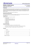
The fixed vector table is allocated to a fixed address range. The individual vectors for the privileged instruction
exception, undefined instruction exception, floating-point exception, non-maskable interrupt, and reset are allocated to
addresses in the range from FFFFFF80h to FFFFFFFFh. Also included in the fixed vector table are some locations that
are reserved for system configuration and ROM protection. Figure 3- Fixed Vector Table shows the fixed vector table.
Figure 3- Fixed Vector Table
Address
FFFFFF80h
FFFFFF84h
FFFFFF88h
FFFFFF8Ch
FFFFFF90h –
FFFFFF98h
FFFFFF9Ch
FFFFFFA0h –
FFFFFFCCh
FFFFFFA0h –
FFFFFFACh
FFFFFFD0h
FFFFFFD4h
FFFFFFD8h
FFFFFFDCh
FFFFFFE0h
FFFFFFE4h
FFFFFFE8h –
FFFFFFF4h
FFFFFFF8h
FFFFFFFCh
Description
Endian select register (MDES) in single-chip mode
(Reserved)
Option Function Select Register 1 (OFS1)
Option Function Select Register 2 (OFS2)
(Reserved)
ROM protection code
(Reserved)
ID Code for flash protection
Privileged instruction exception
Access exception
(Reserved)
Undefined instruction exception
(Reserved)
Floating-point exception
(Reserved)
Non-maskable interrupt
Reset
Do not store data in areas marked “Reserved” in the fixed vector table; some of these areas are used by the RX for
specific functions such as the code protection mechanism. User data must be stored below address FFFF FF80h.
12.2.2
Relocatable Vector Table
The address where the relocatable vector table is placed can be adjusted. The table is a 1,024-byte region that contains
all vectors for unconditional traps and interrupts and starts at the address (IntBase) specified in the interrupt table
register (INTB). Figure 4 - Relocatable Vector Table shows the relocatable vector table.
Each vector in the relocatable vector table has a vector number from 0 to 255. Each of the INT instructions, which act
as the sources of unconditional traps, is allocated to the vector that has the same number as that of the instruction itself
(from 0 to 255). The BRK instruction is allocated to the vector with number 0. Furthermore, vector numbers within the
set from 0 to 255 are also allocated to other interrupt sources, such as on-chip peripherals, on a per-product basis.
Note that the value of the Interrupt Table Register (INTB) is undefined after reset. The Renesas tool chain can
automatically generate startup code that initializes the INTB register. INTB can only be changed when the MCU is in
supervisor mode.
R01AN1657EU0111 Rev.1.11
Feb 3, 2014
Page 30 of 37
RX63N, RX631 Group
Quick Design Guide
Figure 4 - Relocatable Vector Table
12.3
Fast Interrupts
For applications where interrupt response is critical, interrupt latency can be reduced through the use of the Fast
Interrupt. The Fast Interrupt specifies one interrupt source in the Fast Interrupt Vector register (FINTV) as a highpriority interrupt, and uses dedicated registers for saving the Program Status Word (BPSW) and Program Counter
(BPC). Further speed enhancements can be realized by instructing the compiler to reserve some of the general purpose
CPU registers for exclusive use by the Fast Interrupt service routine. With a dedicated set of CPU registers reserved for
its sole use, the response of Fast Interrupt service routine is improved by eliminating the need to save and restore
processor context on the stack during entry and exit. The performance of the main application code may be slightly
degraded due to the smaller register set available to it.
12.4
Interrupt Stack Pointers
A separate Interrupt Stack Pointer (ISP) is used during exception processing. This greatly reduces RAM requirements
when using an RTOS since room for an interrupt stack does not need to be allocated as part of each task’s stack. The
ISP is automatically set by the startup code generated by the Renesas tool chain (see “Startup Program Creation” in the
RX Software manual for details). Register R0 is used as the stack pointer and contains the current value of the active
stack pointer (ISP or USP) depending on the processor mode.
12.5
Interrupt Request Groups
In some cases, interrupts from multiple sources are grouped into a single request group. Interrupt signals in each group
are collectively handled by a single interrupt request and vector. Within each group, individual sources may be enabled
or disabled. Refer to the Interrupt Control Unit (ICU) chapter in the hardware manual for details.
12.6
Interrupt Unit Selection
For some MTU and TPU interrupt sources, request from the two peripheral modules are handled as one interrupt
request. The ICU can be set to service either the MTU or TPU interrupts through the single request and vector. Refer
to the section “Unit Selection’ in the Interrupt Control Unit (ICU) chapter in the hardware manual for details.
R01AN1657EU0111 Rev.1.11
Feb 3, 2014
Page 31 of 37
RX63N, RX631 Group
Quick Design Guide
13. Low Power Consumption
The RX63N has register settings that allow the MCU to operate with lower power consumption. These modes are
referred to as the Operating Power Control Modes and are controlled by the OPCCR register. Below is a summary of
these modes and the maximum permissible clocking and voltage levels under each mode.
Table 8 - Operating Power Control Modes
Operating Power
Control Mode
OPCM
[2] bits
Operating Frequency/Voltage Range
During Flash READ
During Flash
PROGRAM/ERASE
ICLK
(max)
FCLK
(max)
PCLKA
(max)
PCLKB
(max)
BCLK
(max)
Voltage V
FCLK
Voltage V
High Speed
Operating Mode
000b
100 MHz
50 MHz
100 MHz
50 MHz
100 MHz
2.7-3.6
4-50
MHz
2.7-3.6
Low Speed
Operating Mode 1
110b
1 MHz
1 MHz
1 MHz
1 MHz
1 MHz
2.7-3.6
P/E
Disabled
P/E
Disabled
Low Speed
Operating Mode 2
111b
32 - 125
KHz
32 - 125
KHz
125 KHz
125 KHz
125 KHz
2.7-3.6
P/E
Disabled
P/E
Disabled
Note that while it may be possible to set the value in the OPCCR register to any of the low power operating modes,
unless the clocking and voltage levels are not already set to meet the requirements of said mode, setting the OPCCR
register will not have any effect in lowering power consumption.
In order to achieve the lowest power numbers, use the maximum possible dividers in the clock generation circuits.
In addition to the Operating Power Control Modes, the RX63N also has Low Power Consumption modes where the
CPU is inactive and the other peripherals/clocks are switched on or off depending on how much power needs to be
conserved. These modes are activated by configuring the appropriate control registers (refer to Figure 11.1 in the
hardware manual) and then executing the wait() instruction.
Since the low power modes can be exited on receiving an interrupt, all pending requests should be handled and the I
flag cleared prior to executing the wait() instruction.
The table below is a summary of the three Low Power Consumption modes:
R01AN1657EU0111 Rev.1.11
Feb 3, 2014
Page 32 of 37
RX63N, RX631 Group
Quick Design Guide
Table 9 – Low Power Consumption Modes
State of
operation
Transition
condition
Canceling
method other
than resets
State after
cancellation *4
Main Clock
Oscillator
Sub-Clock
Oscillator
High Speed OnChip Oscillator
Low Speed OnChip Oscillator
IWDT-dedicated
On-Chip
Oscillator
PLL
CPU
Sleep Mode
All-Module Clock
Stop Mode
Software Standby
Mode
Deep Software
Standby Mode
Control register +
instruction
Interrupt
Control register +
instruction
Interrupt *1
Control register +
instruction
Interrupt *2
Control register +
instruction
Interrupt *3
Program execution
state (interrupt
processing)
Operation possible
Program execution
state (interrupt
processing)
Operation possible
Operation possible
Operation possible
Operation possible
Operation possible
Program execution
state (interrupt
processing)
Operation
possible*5
Operation
possible*6
Stopped
Program execution
state (reset
processing)
Operation
possible*5
Operation
possible*6
Stopped
Operation possible
Operation possible
Stopped
Stopped
Operation possible*7
Operation
possible*7
Operation
possible*7
Stopped
(undefined) *7
Operation possible
Stopped (retained)
Operation possible
Stopped (retained)
Stopped
Stopped (retained)
Stopped
Stopped
(undefined)
Stopped
(undefined)
Operation possible
Stopped (retained)
Stopped (retained)
On-chip RAM 1
(retained)
(0001 0000h to
0001 FFFFh)
Operation possible
Stopped (retained)
Stopped (retained)
On-chip RAM 0
(retained)
(0000 0000h to
0000 FFFFh)
Operating
Stopped (retained)
Stopped (retained)
Flash Memory
Operating possible
Stopped
Stopped (retained)
USB 2.0
(retained)*9
Host/Function
Stopped (retained)
Stopped (retained)
Stopped (retained)
Watchdog timer
(WDT)
Operation possible*7 Operation
Operation
Independent
possible*7
possible*7
Watchdog Timer
(IWDT)
Operation possible
Operation possible
Operation possible
Realtime clock
(RTC)
Operation
Stopped (retained)
8-bit timer (unit 0, Operation possible
possible*11
unit 1) (TMR)
Operation possible
Operation possible
Voltage detection Operation possible
circuit (LVD)
Operating
Operating
Operating
Power-on reset
circuit
Operation possible
Stopped(Retained) Stopped(Retained)
Peripheral
modules
Operating
Retained *14
Retained *15
I/O pin state
Note : Refer to table 11.2 in the hardware manual for additional information relevant to this table.
R01AN1657EU0111 Rev.1.11
Feb 3, 2014
Stopped (retained/
undefined)*8
Stopped (retained)
Stopped (retained/
undefined) *10
Stopped
(undefined)
Stopped
(undefined) *7
Operation possible
Stopped
(undefined)
Operation
possible*12*13
Operating*13
Stopped
(undefined)
Retained *15
Page 33 of 37
RX63N, RX631 Group
Quick Design Guide
14. External buses
Some members of the RX family include external bus controllers and SDRAM controllers.
14.1
Endian of External Memory Areas
Memory accesses for devices connected to external buses may be configured by software for big endian or little endian
access. The access mode is set on a per-chip-select basis by setting the EMODE bit in the chip select control register
(CSiCR) or the SDC mode register (SDCMOD). Note that the EMODE bit changes the access relative to the MCU’s
main operating mode which is specified in the MDEB and MDES registers. Instruction code can only be allocated in an
external memory area when its endian matches that of the MCU (EMODE = 0). See the table below for example
configurations.
MDE
CPU Endian
EMODE
Access to external devices
Can MCU run instruction code from this area?
7
Little endian
0
Little endian
Yes
0
Big Endian
1
Little endian
No
0
Big Endian
0
Big endian
Yes
7
Little Endian
1
Big endian
No
14.2
Bus Width & Multiplexing
The access width of external memory areas can be set to 8-bit, 16-bit, or 32-bit. Width settings are set on a per-chipselect basis by setting the BSIZE bits in the CSiCR register or the SDC Control Register (SDCCR). The address and
data lines of chip-select regions can be multiplexed by setting the MPXEN bit in the CSiCR register. Note that if
MPXEN bit is set (data and address lines are multiplexed) then 32-bit access width should not be chosen since operation
cannot be guaranteed.
14.3
Drive Strength for Bus Signals
When using an external memory area, pins that control the bus signals should be set for high-drive capacity output. See
Section 10.1.3 for more information on setting the drive capacity of a pin.
14.4
Bus Errors
Two types of bus errors can be detected: illegal address accesses and bus access timeouts. Illegal address errors are
detected for external areas that are disabled, and for reserved areas. Reference Section Error! Reference source not
found. for locations of reserved areas. Timeout errors are detected when bus accesses do not complete in 768 cycles.
When a bus error occurs the bus error interrupt (BURERR) will be generated. The code below shows the enabling of the
bus error interrupt.
R01AN1657EU0111 Rev.1.11
Feb 3, 2014
Page 34 of 37
RX63N, RX631 Group
Quick Design Guide
/* Enable the bus error interrupt to catch accesses to illegal/reserved areas of
memory and bus access timeouts. The ISR for this interrupt can be found below
in the function "bus_error_isr" */
/* Clear any pending interrupts */
IR(BSC,BUSERR) = 0;
/* Make this the highest priority interrupt (adjust as necessary for your
application). */
IPR(BSC,BUSERR) = 0x0F;
/* Enable the interrupt in the ICU*/
IEN(BSC,BUSERR) = 1;
/* Enable illegal address interrupt in the BSC */
BSC.BEREN.BIT.IGAEN = 1;
/* Enable timeout detection interrupt in the BSC */
BSC.BEREN.BIT.TOEN = 1;
The code below shows an example of a bus error interrupt handler.
/*******************************************************************************
* Function name: bus_error_isr
* Description : This interrupt will fire if the user tries to access code or
*
data from one of the reserved areas in the memory map,
*
including the areas covered by disabled chip selects. This
*
interrupt will also fire if a bus timeout is detected. A nop()
*
statement is included here as a convenient place to set a
*
breakpoint during debugging and development, and further
*
handling should be added by the user for their application.
* Arguments
: none
* Return value : none
*******************************************************************************/
#pragma interrupt (bus_error_isr(vect=VECT(BSC,BUSERR)))
void bus_error_isr (void)
{
/* Clear the bus error */
BSC.BERCLR.BIT.STSCLR = 1;
/* To find the address that was accessed when the bus error occurred, read
the register BSC.BERSR2.WORD. The upper 13 bits of this register contain
the upper 13-bits of the offending address (in 512K byte units). */
/* nop() for convenience of setting a breakpoint. */
nop();
}
R01AN1657EU0111 Rev.1.11
Feb 3, 2014
Page 35 of 37
RX63N, RX631 Group
Quick Design Guide
15. References
The following documents were used in creating this Quick Design Guide:
Reference
1
2
3
Document Number
R01UH0041EJ0160_RX63N631
R20UT0398EJ0300_E1E20
R20UT0399EJ0600_E1E20_RX
4
5
6
7
R01AN0252ET0101_RX
R01AN0287EU0300_RX
R01AN0544EU0240
R01AN1245EJ0100
R01AN1657EU0111 Rev.1.11
Feb 3, 2014
Description
RX63N Group, RX631 Group User Manual: Hardware
E1 Emulator E20 Emulator User’s Manual
E1/E20 Emulator Additional Document for User’s Manual
(RX User System Design)
RX Family Debug Console Function Using E1
RX600 & RX200 Series The Flash Loader Project
RX600 & RX200 Series Simple Flash API for RX
RX63N Group, RX631 Group Initial Setting
Page 36 of 37
RX63N, RX631 Group
Quick Design Guide
Website and Support
Renesas Electronics Website
http://www.renesas.com/
Inquiries
http://www.renesas.com/inquiry
All trademarks and registered trademarks are the property of their respective owners.
R01AN1657EU0111 Rev.1.11
Feb 3, 2014
Page 37 of 37
Revision Record
Rev.
1.00
1.10
Date
Apr.10.2013
July.4.2013
1.11
Feb.3.2014
Description
Page
Summary
—
First edition issued
9
Added setup for big-endian mode
Described initial states of system clocks after reset
11
Added section 5.5
12
Added reference to Low CL Sub-Clock app note
18
Added details about enabling external bus and disabling onchip ROM
Added section 10.7
27
7
Corrected typo in table 2 (PC7 column)
8
“Independent Watchdog Timer” was incorrectly called “Internal
Watchdog Timer”
A-1
General Precautions in the Handling of MPU/MCU Products
The following usage notes are applicable to all MPU/MCU products from Renesas. For detailed usage notes on the
products covered by this document, refer to the relevant sections of the document as well as any technical updates that
have been issued for the products.
1. Handling of Unused Pins
Handle unused pins in accordance with the directions given under Handling of Unused Pins in the
manual.
The input pins of CMOS products are generally in the high-impedance state. In operation with an
unused pin in the open-circuit state, extra electromagnetic noise is induced in the vicinity of LSI, an
associated shoot-through current flows internally, and malfunctions occur due to the false
recognition of the pin state as an input signal become possible. Unused pins should be handled as
described under Handling of Unused Pins in the manual.
2. Processing at Power-on
The state of the product is undefined at the moment when power is supplied.
The states of internal circuits in the LSI are indeterminate and the states of register settings and
pins are undefined at the moment when power is supplied.
In a finished product where the reset signal is applied to the external reset pin, the states of pins
are not guaranteed from the moment when power is supplied until the reset process is completed.
In a similar way, the states of pins in a product that is reset by an on-chip power-on reset function
are not guaranteed from the moment when power is supplied until the power reaches the level at
which resetting has been specified.
3. Prohibition of Access to Reserved Addresses
Access to reserved addresses is prohibited.
The reserved addresses are provided for the possible future expansion of functions. Do not access
these addresses; the correct operation of LSI is not guaranteed if they are accessed.
4. Clock Signals
After applying a reset, only release the reset line after the operating clock signal has become stable.
When switching the clock signal during program execution, wait until the target clock signal has
stabilized.
When the clock signal is generated with an external resonator (or from an external oscillator)
during a reset, ensure that the reset line is only released after full stabilization of the clock signal.
Moreover, when switching to a clock signal produced with an external resonator (or by an external
oscillator) while program execution is in progress, wait until the target clock signal is stable.
5. Differences between Products
Before changing from one product to another, i.e. to a product with a different part number, confirm
that the change will not lead to problems.
The characteristics of an MPU or MCU in the same group but having a different part number may
differ in terms of the internal memory capacity, layout pattern, and other factors, which can affect
the ranges of electrical characteristics, such as characteristic values, operating margins, immunity
to noise, and amount of radiated noise. When changing to a product with a different part number,
implement a system-evaluation test for the given product.
Notice
1.
Descriptions of circuits, software and other related information in this document are provided only to illustrate the operation of semiconductor products and application examples. You are fully responsible for
the incorporation of these circuits, software, and information in the design of your equipment. Renesas Electronics assumes no responsibility for any losses incurred by you or third parties arising from the
use of these circuits, software, or information.
2.
Renesas Electronics has used reasonable care in preparing the information included in this document, but Renesas Electronics does not warrant that such information is error free. Renesas Electronics
assumes no liability whatsoever for any damages incurred by you resulting from errors in or omissions from the information included herein.
3.
Renesas Electronics does not assume any liability for infringement of patents, copyrights, or other intellectual property rights of third parties by or arising from the use of Renesas Electronics products or
technical information described in this document. No license, express, implied or otherwise, is granted hereby under any patents, copyrights or other intellectual property rights of Renesas Electronics or
others.
4.
You should not alter, modify, copy, or otherwise misappropriate any Renesas Electronics product, whether in whole or in part. Renesas Electronics assumes no responsibility for any losses incurred by you or
third parties arising from such alteration, modification, copy or otherwise misappropriation of Renesas Electronics product.
5.
Renesas Electronics products are classified according to the following two quality grades: "Standard" and "High Quality". The recommended applications for each Renesas Electronics product depends on
the product's quality grade, as indicated below.
"Standard": Computers; office equipment; communications equipment; test and measurement equipment; audio and visual equipment; home electronic appliances; machine tools; personal electronic
equipment; and industrial robots etc.
"High Quality": Transportation equipment (automobiles, trains, ships, etc.); traffic control systems; anti-disaster systems; anti-crime systems; and safety equipment etc.
Renesas Electronics products are neither intended nor authorized for use in products or systems that may pose a direct threat to human life or bodily injury (artificial life support devices or systems, surgical
implantations etc.), or may cause serious property damages (nuclear reactor control systems, military equipment etc.). You must check the quality grade of each Renesas Electronics product before using it
in a particular application. You may not use any Renesas Electronics product for any application for which it is not intended. Renesas Electronics shall not be in any way liable for any damages or losses
incurred by you or third parties arising from the use of any Renesas Electronics product for which the product is not intended by Renesas Electronics.
6.
You should use the Renesas Electronics products described in this document within the range specified by Renesas Electronics, especially with respect to the maximum rating, operating supply voltage
range, movement power voltage range, heat radiation characteristics, installation and other product characteristics. Renesas Electronics shall have no liability for malfunctions or damages arising out of the
use of Renesas Electronics products beyond such specified ranges.
7.
Although Renesas Electronics endeavors to improve the quality and reliability of its products, semiconductor products have specific characteristics such as the occurrence of failure at a certain rate and
malfunctions under certain use conditions. Further, Renesas Electronics products are not subject to radiation resistance design. Please be sure to implement safety measures to guard them against the
possibility of physical injury, and injury or damage caused by fire in the event of the failure of a Renesas Electronics product, such as safety design for hardware and software including but not limited to
redundancy, fire control and malfunction prevention, appropriate treatment for aging degradation or any other appropriate measures. Because the evaluation of microcomputer software alone is very difficult,
please evaluate the safety of the final products or systems manufactured by you.
8.
Please contact a Renesas Electronics sales office for details as to environmental matters such as the environmental compatibility of each Renesas Electronics product. Please use Renesas Electronics
products in compliance with all applicable laws and regulations that regulate the inclusion or use of controlled substances, including without limitation, the EU RoHS Directive. Renesas Electronics assumes
no liability for damages or losses occurring as a result of your noncompliance with applicable laws and regulations.
9.
Renesas Electronics products and technology may not be used for or incorporated into any products or systems whose manufacture, use, or sale is prohibited under any applicable domestic or foreign laws or
regulations. You should not use Renesas Electronics products or technology described in this document for any purpose relating to military applications or use by the military, including but not limited to the
development of weapons of mass destruction. When exporting the Renesas Electronics products or technology described in this document, you should comply with the applicable export control laws and
regulations and follow the procedures required by such laws and regulations.
10. It is the responsibility of the buyer or distributor of Renesas Electronics products, who distributes, disposes of, or otherwise places the product with a third party, to notify such third party in advance of the
contents and conditions set forth in this document, Renesas Electronics assumes no responsibility for any losses incurred by you or third parties as a result of unauthorized use of Renesas Electronics
products.
11. This document may not be reproduced or duplicated in any form, in whole or in part, without prior written consent of Renesas Electronics.
12. Please contact a Renesas Electronics sales office if you have any questions regarding the information contained in this document or Renesas Electronics products, or if you have any other inquiries.
(Note 1)
"Renesas Electronics" as used in this document means Renesas Electronics Corporation and also includes its majority-owned subsidiaries.
(Note 2)
"Renesas Electronics product(s)" means any product developed or manufactured by or for Renesas Electronics.
SALES OFFICES
http://www.renesas.com
Refer to "http://www.renesas.com/" for the latest and detailed information.
Renesas Electronics America Inc.
2801 Scott Boulevard Santa Clara, CA 95050-2549, U.S.A.
Tel: +1-408-588-6000, Fax: +1-408-588-6130
Renesas Electronics Canada Limited
1101 Nicholson Road, Newmarket, Ontario L3Y 9C3, Canada
Tel: +1-905-898-5441, Fax: +1-905-898-3220
Renesas Electronics Europe Limited
Dukes Meadow, Millboard Road, Bourne End, Buckinghamshire, SL8 5FH, U.K
Tel: +44-1628-585-100, Fax: +44-1628-585-900
Renesas Electronics Europe GmbH
Arcadiastrasse 10, 40472 Düsseldorf, Germany
Tel: +49-211-6503-0, Fax: +49-211-6503-1327
Renesas Electronics (China) Co., Ltd.
Room 1709, Quantum Plaza, No.27 ZhiChunLu Haidian District, Beijing 100191, P.R.China
Tel: +86-10-8235-1155, Fax: +86-10-8235-7679
Renesas Electronics (Shanghai) Co., Ltd.
Unit 301, Tower A, Central Towers, 555 Langao Road, Putuo District, Shanghai, P. R. China 200333
Tel: +86-21-2226-0888, Fax: +86-21-2226-0999
Renesas Electronics Hong Kong Limited
Unit 1601-1613, 16/F., Tower 2, Grand Century Place, 193 Prince Edward Road West, Mongkok, Kowloon, Hong Kong
Tel: +852-2265-6688, Fax: +852 2886-9022/9044
Renesas Electronics Taiwan Co., Ltd.
13F, No. 363, Fu Shing North Road, Taipei 10543, Taiwan
Tel: +886-2-8175-9600, Fax: +886 2-8175-9670
Renesas Electronics Singapore Pte. Ltd.
80 Bendemeer Road, Unit #06-02 Hyflux Innovation Centre, Singapore 339949
Tel: +65-6213-0200, Fax: +65-6213-0300
Renesas Electronics Malaysia Sdn.Bhd.
Unit 906, Block B, Menara Amcorp, Amcorp Trade Centre, No. 18, Jln Persiaran Barat, 46050 Petaling Jaya, Selangor Darul Ehsan, Malaysia
Tel: +60-3-7955-9390, Fax: +60-3-7955-9510
Renesas Electronics Korea Co., Ltd.
12F., 234 Teheran-ro, Gangnam-Ku, Seoul, 135-920, Korea
Tel: +82-2-558-3737, Fax: +82-2-558-5141
© 2014 Renesas Electronics Corporation. All rights reserved.
Colophon 4.0


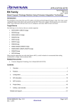
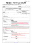
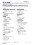
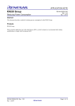

![Theater Management Software V5.6 [v06]](http://vs1.manualzilla.com/store/data/005786775_1-99bc430d529a8a144d04bed9ea0580b8-150x150.png)