1
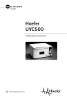
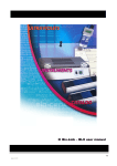
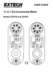
user manual
blotting equipment
Hoefer UVC 500
Ultraviolet Crosslinker
transilluminator
um
UVC500-IM/Rev. F0/04-04
Page finder
UV Crosslinker function and description . . . . . . . . . . . . . .1
Unpacking . . . . . . . . . . . . . . . . . . . . . . . . . . . . . . . . . . . . . . . . . . .2
Specifications. . . . . . . . . . . . . . . . . . . . . . . . . . . . . . . . . . . . . . . .3
Important safety information . . . . . . . . . . . . . . . . . . . . . . . . . .4
Operating instructions . . . . . . . . . . . . . . . . . . . . . . . . . . . . . . . .5
Energy setting
Time setting
. . . . . . . . . . . . . . . . . . . . . . . . . . . . . . . . . . . . . . .6
. . . . . . . . . . . . . . . . . . . . . . . . . . . . . . . . . . . . . . . . .8
Care and maintenance
.............................
10
Bibliography . . . . . . . . . . . . . . . . . . . . . . . . . . . . . . . . . . . . . . . 12
Ordering information . . . . . . . . . . . . . . . . . . . . . . . . . . . . . . . 14
• pi
UV Crosslinker function and description
The Hoefer™ UVC 500 Ultraviolet Crosslinker
provides a uniform and intense source of ultraviolet (UV) light for such uses as:
• DNA crosslinking
• DNA nicking
• Rapid restriction site mapping
• Testing RecA function
• Ultraviolet sterilization
• Elimination of PCR contamination
The internal photo-feedback system continually
measures the energy delivered within the chamber
and automatically deactivates the UV light source
once the programmed energy level is reached.
This system also automatically adjusts to variations in UV intensity that occur as lamps age.
Fig 1. Crosslinker front view.
Pull the door open along this handle
View window
LED display
Keypad
Power switch
• p1
Unpacking
Unwrap all packages carefully and compare
contents with the packing list, making sure all
items arrived. If any part is missing, contact
your local sales office. Inspect all components
for damage that may have occurred while the
unit was in transit. If any part appears damaged,
contact the carrier immediately. Be sure to keep
all packing material for damage claims or to use
should it become necessary to return the unit.
• p2
Specifications
Ultraviolet wavelength and sources
• 254 nm (shortwave)
• Five 8-W 254 nm UV dual bi-pin discharge
type tubes
Features
• Microprocessor controlled UV sensor feedback
system
• Large LED readout
• Tactile membrane switch keypad
• Laydown-type door
• Multiple set functions: pre-set UV energy or time
exposure user-specified UV
energy or time exposure
• Max. energy setting
999,900 µJ/cm2
• Max. time setting:
999.9 min
Dimensions (h × d × w)
External
Chamber interior
22.2 × 34.9 × 40.0 cm
(8.75 × 13.75 × 15.75 in.)
12.7 × 30.5 × 25.4 cm
(5 × 12 × 10 in.)
Input fuses
• 115 V - F 1A/250V 5 × 20 mm (2 fuses)
• 230 V - F 1A/250V 5 × 20 mm (2 fuses)
Weight
• 7.5 kg (15.5 lbs)
Safety
• Safety interlocked door
• UV-blocking view window
• Safety-fused and removable power cord
Safety certifications
CE 89/336/EEC (EMC directive), CE 73/23/EEC (LV
directive), EN-61010-1 (IEC1010-1, UL3101-1,
CSA22.2 1010-1)
• p3
Important safety information
• Always wear protective gloves and goggles when
working with the crosslinker.
• The UVC 500 is a powerful source of ultraviolet radiation. The door is safety interlocked to
prevent accidental user exposure to UV light.
Do not attempt to override the safety interlocks.
If the safety interlock is disengaged, the UV
lamps do not light and the unit will beep 3 times
when the START key is pressed.
If a malfunction occurs and the lamps in the
crosslinker remain on when the door is open,
immediately close the door and turn off the
mains power.
• The view window blocks UV radiation and
allows viewing while the unit is in operation.
If the window is broken or removed, stop using
the crosslinker immediately.
• Always disconnect the mains power cord before
cleaning the unit or replacing fuses or lamps.
• p4
Operating instructions
Set up and membrane placement
1
Place the unit on a stable and level surface.
2
Note: To protect the crosslinker from corrosive buffers,
lay a piece of plastic wrap
on the compartment bottom
before placing the blotting
paper and sample.
Plug the power cord into the receptacle at the back of
the unit and into a properly grounded electrical outlet
of the proper power rating.
3
Flip the power mains switch located under the
keypad to on (–).
Note: The instrument settings are always the values
last programmed, and are indicated by the LED
display and a lit red indicator lamp.
4
Open the door by pulling the door handle above the
window toward you.
Note: Do not obstruct or damage the photofeedback
sensor, which is mounted on a small metal tab
protruding from the lower right side.
5
Moisten (do not wet completely) a sheet of blotting
paper with transfer buffer and place it in the center
of the compartment. Place the membrane on the
paper with the nucleic acid side facing upward.
6
Set the energy exposure (energy or time) as described
in the next section.
• p5
Energy setting
Note: Multiply all displayed
energy settings by 100 for
the actual energy value.
UVC 500 Crosslinker
user interface
The LED display shows values for
energy (multiply by 100 for actual
value in µJ/cm2) and time (in
minutes and tenths of a minute.)
The amount of energy recommended for UV
crosslinking of DNA and RNA by covalently
binding nucleic acids to Hybond™ membranes
after Northern, Southern, slot or dot blotting
is 70,000 µJ/cm2. This value is preset at the
factory and displays as 700 on the LED display,
which only shows 4 digits. As the unit operates,
a countdown of the remaining energy to be emitted is displayed on the LED.
Using the preset energy setting
1
First press the PRESET key and then the ENERGY
key. The red indicator lamp next to each of these
keys should light and the LED should display 700
(or the value last programmed).
2
Press the green START key. The UV lamps take a few
seconds to energize before the countdown value is
displayed. At the end of the exposure, the unit automatically stops and beeps 5 times.
Reprogramming the preset energy setting
1
Press and hold the PRESET key until you hear a
second beep. The lamp next to the PRESET key
flashes when this key switches to program mode.
2
Press the ENERGY key. Use the numeric keypad to
enter the new value. The LED display should show
the new value.
3
Press the ENTER key.
• p6
Programming the ENERGY key
1
Press the ENERGY key.
2
Enter a value using the numeric keypad. The LED will
display the new value.
3
Press ENTER. After programming, pressing the
ENERGY key retrieves this setting. Change the setting
by entering a new value and pressing the ENTER key.
• p7
Time setting
The display shows time in minutes and tenths of
a minute.
Using the preset time setting
1
First press the PRESET key and then the TIME key.
The red indicator lamp next to each of these keys
should light and the LED should display 5.0 (or the
value last programmed).
2
Press the green START key. The UV lamps take a few
seconds to energize before the countdown value is
displayed. At the end of the exposure, the unit automatically stops and beeps 5 times.
Reprogramming the preset time setting
1
Press and hold the PRESET key until you hear the
second beep. The lamp next to the PRESET key
flashes when this key switches to program mode.
2
Press the TIME key. Use the numeric keypad to enter
the new value. The LED display shows the new value.
3
Press the ENTER key.
• p8
Programming the TIME key
1
Press the TIME key.
2
Enter a value using the numeric keypad. The LED will
display the new value.
3
Press the ENTER key. After programming, pressing the TIME key retrieves this setting. Change the
setting by entering a new value and pressing ENTER.
Stopping and restarting the crosslinker
• Press the red STOP/RESET key to stop the
exposure. The LED will display the remaining
exposure level or time.
• Press the green START key to restart the exposure. The program will continue from where it
was stopped.
• To enter a different value once the program has
started, press STOP/RESET, enter the new value,
then press ENTER. Press the START key to begin
the new exposure value.
• To revert to the last used setting after the exposure is interrupted, press the STOP/RESET key a
second time. Press START to start exposure from
the previous setting.
• If the door is accidentally opened during exposure, the UV lamps instantly turn off and the
remaining exposure level or time is displayed on
the LED display. To restart, close the door and
press the START key.
• p9
Care and maintenance
Cleaning
Caution! Always turn the
mains power switch off and
unplug the instrument
before cleaning.
Preventative maintenance includes regular cleaning of the compartment surface, the sensor, and
UV lamps.
• Use mild soap and water on a soft cloth or
sponge to clean the exterior.
• Gently wipe the photofeedback sensor and UV
lamps regularly with a soft cotton cloth dampened with alcohol.
• Always wipe any water and spills from the inside
of the unit and clean away all chemicals after
each use.
• Never use abrasive cleaners, acetone or chloroform on any part.
Important! The photofeedback system is calibrated
to 254 nm UV light. Do not
install lamps rated for a
different wavelength.
Replacing UV lamps
Periodically check that all five lamps function
by looking through the view window while the
unit is on. If one or more lamps are burned out,
it is recommended that all five be replaced at the
same time. To replace each lamp:
1
Turn off the mains power switch and disconnect the
power cord.
2
Locate the lamps along the top of the compartment.
Remove each lamp by carefully rotating it 1/4 – 1/3
turn and then carefully pulling it loose.
3
To insert the new lamp, hold it so that the metal
plugs at the ends align vertically. Place the lamp in
the sockets at each end of the unit and lightly push it
up into place. Rotate the lamp to lock it into place.
• p10
Replacing fuses
Fuses protect equipment by disconnecting loads
too large for the instrument’s circuit design. For
continued protection, only use fuses with the
specified voltage and current rating.
Each of two round modules on the left side of
the control panel (above the mains power cord
receptacle) holds one F 1A/250V 5 × 20 mm
(Fast blo) fuse.
1
Caution! Set the mains power switch to off and
detach the power cord before replacing fuses.
2
Insert a small flat-blade screwdriver into the slot on
the fuse module and turn it 1/4 turn counterclockwise. The spring-loaded module cap will loosen and
you can then pull the cap/fuse holder out.
3
Pull the fuse out of its holder and inspect. If the fuse
element is burned or broken, replace the fuse with an
identical type. If the fuse appears to be intact, check
it with an ohmmeter.
4
Fig 2. UVC 500 Crosslinker back
view 115 V model.
Insert a good fuse into the holder and then insert
this assembly back into the unit. Seat the module by
inserting the screwdriver into the slot, pressing gently,
and turning the cap 1/4 turn clockwise.
Model ID and power specifications
Fuse modules (2)
Mains power cord receptacle
• p11
Bibliography
DNA crosslinking
Church, M. C. and G. Gilbert. (1984) Genomic
sequencing. Proc Natl. Acad. Sci., USA. 81,
1991–1995.
Khandjian, E. W. (1987) Optimized hybridization of DNA blotted and fixed to nitrocellulose and nylon membranes. BioTechnology. 5,
165–167.
Khandjian, E. W. (1986) UV crosslinking of
RNA to nylon membrane enhances hybridization signals. Molec. Biol. Report. 11, 107–115.
Reed, K. C. and D. A. Mann. (1985) Rapid
transfer of DNA from agarose gels to nylon
membranes. Nuc. Acid Res. 13, 7207–7221.
DNA nicking
Vollrath, D. and R. W. Davis. (1987) Resolution
of DNA molecules greater than 5 megabases by
contour-clamped homogeneous electric fields.
Nuc. Acid Res. 15, 7865–7876.
Rapid restriction site mapping
Whittaker, P. A. and E. M. Southern. (1986)
Ultraviolet irradiation of DNA: A way of generating partial digests for rapid restriction site
mapping. Gene. 41, 129–134.
Testing RecA function
Maniatis, T. (1989) Maintenance and Testing of
Lysogens of Bacteriophage Lambda in Molecular
Cloning: A Laboratory Manual, eds. Sambrook,
Fritsch and Maniatis. 2.96.
• p12
Ultraviolet sterilization
Reich, R. R., and Anderson, H. D. (1986) Sterilization of Membrane Filters with Ultraviolet
Radiation. Pharmaceutical Manufacturing. Jan.
Elimination of PCR contamination
WIlson, K. H. (1992) UV Absorption Complicates PCR Decontamination, BioTechniques. 13,
208–210.
Sarkar, Gobinda, and Sommer, Steve S. (1991)
Parameters Affecting Susceptibility of PCR
Contamination to UV Inactivation, BioTechniques, 10, 590–594.
Sarkar, Gobinda, and Sommer, Steve S. (1990)
Shedding Light on PCR Contamination. Nature.
343, 27.
Yamada, H. and Hieda, K. (1992) Wavelength
Dependence (150-290nm) of the Formation of
the Cyclobutane Dimer and the (6-4) Photoproduct of Thymine. Photochemistry and Photobiology. 55, 541–548.
• p13
Ordering information
product
Hoefer UVC Ultraviolet Crosslinker
For membranes to 25 × 30 cm.
115 VAC
230 VAC
• p14
qty.
1
1
code
number
UVC500-115V
UVC500-230V
Replacement UV lamp, 8 W, 254 nm 1
UVLS-8
Replacement fuses
PSF1A-F8-5X20
5
• p15
Hoefer, Inc.
953 Indiana Street
San Francisco, CA
94107 USA
www.hoeferinc.com
© 2004 Hoefer, Inc.—
All rights reserved.
Printed in the USA
• p16