1
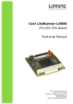
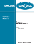
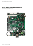
Embedded Software Components
2007 Product Catalog
Empowering Embedded Systems
949 Crestview Circle
Weston, FL 33327
U.S.A.
Tel.: +1 954 217 2036
FAX: +1 954 217 2037
www.micrium.com
Empowering Embedded Systems
Micrium royalty-free software
targets the embedded market
Micrium’s vision is to provide the highest-quality embedded software components
in industry, in the form of engineer-friendly source code with unsurpassed documentation
and customer support. Micrium’s products consistently deliver on that vision to
shorten time-to-market throughout all product development cycles.
Micrium’s world-renowned real-time operating system, the Micrium μC/OS-II was
the first product to embrace this vision. The company’s flagship product, it features the
highest-quality source code available for today's embedded market. The industry’s
acceptance and praise for μC/OS-II proves that Micrium’s vision and strategy have
successfully hit their target within embedded industry.
Today, Micrium delivers to the embedded marketplace a full portfolio of embedded
software components that complement μC/OS-II. A TCP/IP stack, USB stack, CAN stack,
File System (FS), Graphical User Interface (GUI), as well as many other high quality
embedded components are now available.
The development process at Micrium enforces strict coding standards, code reviews
and clear and concise documentation. This process was instrumental in creating a
Validation Suite™ for μC/OS-II that provides all documentation necessary to deliver
μC/OS-II as a pre-certifiable software component for such safety critical systems as
avionics RTCA DO-178B and EUROCAE ED-12B; medical FDA 510(k); and IEC 61058 standard
for transportation and nuclear systems.
Micrium's μC/OS-II is immediately certifiable for the highest criticality systems,
including DO-178B Level A, Class III medical devices, and SIL3/SIL4 IEC-certified systems.
Even when products under development are not safety critical, the certifications represent
proof points that Micrium's μC/OS-II is the most robust and reliable RTOS available.
Micrium believes so strongly in its approach to developing embedded software that
the company works very closely with educational institutions to help future embedded
software engineers learn the Micrium way.
We encourage you to take a look at our catalog to find how the Micrium μC/ product
family has expanded over the past few years. Your comments and questions are
more than welcome.
The μC/Team at Micrium.
μC/Probe is a Microsoft Windows application that allows you to
display the value (at run-time) of virtually any variable, memory
location and I/O port in your product. μC/Probe allows you to display
these variables as analog gauges, numeric indicators, thermometers, bar charts, spreadsheets, pie charts, LEDs, and many other
visualization methods without requiring you to write any code in
your product. No need to use printf() statements, no need to
include a user interface in your product, simply include a stub
(provided in source form) in your target and you can start looking
at the behavior of your embedded system as you are developing
your product.
You can use μC/Probe to display the values of temperatures,
pressures, altitudes, process variables, state variables, timers and
counters, computed values, analog inputs and outputs, minimum
and maximum values, execution times, stack usage, I/O registers,
I/O ports, tables and arrays, plot variables over time and many
more. You can display booleans, integers, floats, and ASCII strings.
Works with targets that has or doesn’t have an RTOS.
■
VARIABLES CAN BE DISPLAYED AS:
■
■
■
■
■
■
■
■
■
■
USER INPUT
■
■
■
■
■
■
■
■
Analog gauges (round or square, linear or logarithmic scales)
Numeric indicators
Thermometers
Bar charts
Pie charts
Plots (multiple variables per plot)
Spreadsheets/workbooks
LEDs (round, square, any color)
Etc.
Sliders
Knobs
Buttons
Pick Lists
Radio Buttons
Checkboxes
Edit boxes
DISPLAY BITMAPS
■
■
User ‘icons’
Pictures
Works with any compiler/assembler/linker that can generate
an ELF file.
■
■
μC/Probe allows you to create any number of ‘data screens’ where
these variables are displayed allowing you to logically group
different ‘views’ into your product.
FEATURES
■
WORKS WITH ANY PROCESSOR
■
■
■
8-, 16-, 32-, 64-bit or DSP
Uses minimal resources
Fast data update
CAN INTERFACE VIA:
■
■
■
J-Link (ARM-based processors)
RS-232C
TCP/IP
PROJECT MANAGEMENT
■
■
■
■
Supports project hierarchy
Project auto-save / restore
Create data screens in minutes
Unlimited number of data screens
MICRIUM 2007 Product Catalog 3
FEATURES AND BENEFITS
μC/OS-II is a portable, ROMable, scalable, preemptive real-time,
deterministic, multitasking kernel for microprocessors, microcontrollers and DSPs. μC/OS-II can manage up to 250 application tasks
and provides the following services:
Semaphores | Event Flags | Mutual Exclusion Semaphores (to
reduce priority inversions) | Message Mailboxes | Message Queues
| Task Management | Time Management | Fixed Sized Memory
Block Management
μC/OS-II comes with ALL the source code.
In fact, the source code is 100% portable
ANSI C and is probably the cleanest and
most consistent code of any RTOS. The
internals of μC/OS-II are described in the
book MicroC/OS-II, The Real-Time Kernel
(ISBN 1-57820-103-9) by Jean J. Labrosse.
All services provided by μC/OS-II starts
with the prefix ‘OS’. This makes it easier
to know that the functions refer to kernel
services in your application. Also, the
services are neatly grouped by categories: OSTask???() relate to
task management functions, OSQ???() relate to message queue
management, OSSem???() relate to semaphore management etc.
A validation suite has been developed for μC/OS-II and provides all
the documentation necessary to prove that μC/OS-II is suitable for
Safety Critical Systems common to Aviation and Medical products.
Although this feature may not be applicable to your needs, it does
prove that μC/OS-II is a very robust RTOS.
μC/OS-II is now 99% compliant with the Motor Industry Software
Reliability Association (MISRA) C Coding Standards. These standards
were created by MISRA to improve the reliability and predictability
of C programs in critical automotive systems. A detailed μC/OS-II
compliance matrix describing all of MISRA’s 127 C Coding Rules is
available from Micrium’s website.
μC/OS-II runs on a large number of processor architectures and
ports are available (FREE download) from our web site. The vast
number of ports should convince you that μC/OS-II is truly very
portable and thus will most likely be ported to new processors as
they become available.
4 MICRIUM 2007 Product Catalog
μC/OS-II can be scaled to only contain the features you need for
your application and thus provide a small footprint. Depending on
the processor, μC/OS-II can be reduced to as little as 2K bytes of
code space and 300 bytes of data space (excluding stacks).
The execution time for most of the services provided by μC/OS-II
is both constant and deterministic. This means that the execution
times do not depend on the number of tasks running in your
application.
μC/OS-II has been used in hundreds of products from companies
all around the world. Many colleges and Universities worldwide
are also using μC/OS-II in curriculum teaching the subject of
real-time systems. This ensures that engineers in the workplace are
trained and ready to use μC/OS-II in your products.
You can ‘View’ the status of your tasks which are managed by
μC/OS-II with an add-on module called μC/OS-View. To accomplish
this, you add a small target resident module that communicates
with a Microsoft Windows application via an RS-232C serial port.
μC/OS-II KA (Kernel Awareness Plug-In) allows you to display
μC/OS-II’s internal data structures in a convenient series of
Windows integrated with the C-SPY Debugger within the IAR
Embedded Workbench. This provides you with information about
each of the active tasks in the target application, about each
semaphore, mutex, mailbox, queue and event flag group along
with a list of all the tasks waiting on these kernel objects, and
more. This can become very useful to the embedded developer when
testing and debugging applications. Other debuggers also provide
Kernel Awareness for μC/OS-II: Lauterbach, Nohau, iSystem and others.
During the standard development process in OSEK/VDX system
development, the system architect generates one or more system
description files, containing the “OSEK/VDX Implementation
Language” (OIL). The OSEK/VDX Extension includes a template
based code generation tool, which allows the automatic generation
of the necessary target configuration files. The code generation
tool is a command line tool, which can be integrated in any
build process.
■
THE SYSTEM IS CERTIFIED FOR THE FOLLOWING
ENVIRONMENTS:
■
■
■
Freescale MPC5554 with Windriver Compiler
Freescale S12XE with Cosmic Compiler
Other processor / compiler environments on request
OSEK / VDX
This μC/OS-II extension provides the user with a certified
OSEK/VDX application programming interface.
The OSEK/VDX Extension supports the OS conformance classes
BCC1 and ECC1. The COM conformance classes CCCA and CCCB are
provided for internal communication.
Fig. 1 : OSEK/VDX
Extension Overview
Your
Application 1
Your
Application 2
Your System
Generation
OSEK/VDX OIL
OSEK/VDX API
Code
Generation
μC/OS-II
Cfg
μC/OS-II
μC/OS-II Port
OSEK
Cfg
Scope of μC/OS-II
with OSEK/VDX Extension
MICRIUM 2007 Product Catalog 5
μC/TCP-IP is a compact, reliable, high performance TCP/IP
protocol stack. Built from the ground up with Micrium's
renowned quality, scalability and reliability, μC/TCP-IP
enables the rapid configuration of required network
options to minimize your time to market.
FEATURES AND BENEFITS
CLEANEST SOURCE CODE μC/TCP-IP provides you with the highest
quality source code in the industry. μC/TCP-IP is a clean-room
design and is not derived from publicly available Unix stacks, yet
still maintains compatibility with the Berkeley 4.4 socket layer
interface. As with all Micrium products, μC/TCP-IP is written in
ANSI C enabling its usage with a wide array of best-of-class crossdevelopment tools.
PORTABLE μC/TCP-IP can be used on 16, 32 and even some
64-bit CPUs.
HIGH PERFORMANCE μC/TCP-IP was designed specifically for the
demanding requirements of embedded systems. Critical sections
were kept to a minimum and selected run-time validations can be
disabled to enhance performance. μC/TCP-IP implements zero
copy buffer management for highest efficiency.
SCALABLE AND ROMABLE μC/TCP-IP allows you to adjust the
memory footprint based on your requirements. μC/TCP-IP can
be configured to only include only those network modules
absolutely required by your system. When a module is not used,
it’s not included in the build to save valuable memory space for
resource limited embedded systems.
DRIVER DEVELOPMENT If your NIC hardware is not found in the
previous list , you can develop it yourself or contract Micrium to
develop it for you. The Interface Layer documentation provided with
the source code gives you all the functions API required to write your
NIC driver. Again,following the Micrium documentation to understand
how to develop your driver is greatly facilitated by the high quality
standards used by Micrium to generate all its documentation.
THIRD PARTY CERTIFICATION μC/TCP-IP has been designed from
the ground up to be certifiable for use in avionics as well as medical
and other safety critical products. Even if your product is NOT
safety critical, you should view the certification as proof that
μC/TCP-IP is a very robust and highly reliable TCP/IP stack.
MISRA C The source code for μC/TCP-IP follows the Motor Industry
Software Reliability Association (MISRA) C Coding Standards.
RTOS required μC/TCP-IP requires the presence of a Real-Time
Operating System (RTOS) or Kernel for task scheduling and mutual
exclusion. μC/TCP-IP includes all the source code to interface to the
μC/OS-II RTOS, but can easily be used with other RTOSs.
6 MICRIUM 2007 Product Catalog
Description
Integrated MAC
Integrated MAC
External Ethernet Controller
External Ethernet Controller
Integrated MAC
Integrated MAC
Integrated MAC
Integrated MAC
External Ethernet Controller
External Ethernet Controller
Integrated MAC
Soft core Ethernet MAC
▲
MEMORY FOOTPRINT
ROM Size
ADD-ON
OPTIONS
Compiler
optimized
for Size
Compiler
optimized
for Speed
μC/DHCPc
2.2K
2.5K
μC/DNSc
1.9K
1.9K
μC/FTPc
N/A
N/A
μC/FTPs
9.5K
9.7K
μC/HTTPs
6.3K
6.5K
μC/POP3c
N/A
N/A
μC/PPP
N/A
N/A
μC/SMTPc
μC/SNTPc
N/A
1.5K
N/A
1.4K
μC/TFTPs
2.5K
2.6K
RAM Size
Typical Configuration
Number of small and
larger buffers
Number of timers
Number of timers
Number of ARP cache entries
Number of TCP connections
Number of sockets
ALL OPTIONS ENABLED ALL OPTIONS DISABLED
μC/TCP-IP
Protocol Layers
BSD Sockets
UDP
TCP
ICMP
IF
ARP
OS
μC/PPP (Optional)
NIC (Ethernet/Serial)
μC Options
Disabled
μC Options
Enabled
54.0
54.8
μC/TCP-IP
TOTAL
3.7
3.8
2.2
2.3
Add-on Options
ARP
5.1
5.3
3.3
3.7
10.8
11.3
7.3
7.8
ICMP
5.7
6.0
3.2
3.3
UDP
2.4
2.5
1.1
1.2
TCP
40.0
45.0
31.7
37.3
μC/DHCPc = 1.2
μC/DNSc = DNSc_MAX_HOSTNAME_SIZE * DNSc_MAX_CACHED_HOSTNAMES
μC/TFTPs = sizeof(OS_STK) * TFTP_CFG_TASK_STK_SIZE
μC/FTPs = sizeof(OS_STK) * FTP_CFG_TASK_STK_SIZE
μC/HTTPs = sizeof(OS_STK) * HTTP_CFG_TASK_STK_SIZE
Sockets
18.3
20.0
11.5
12.5
0.6
0.7
0.0
0.0
29.0
30.8
15.8
17.9
115.6
125.4
76.1
85.9
BSD
CPU
Compiler Compiler Compiler Compiler
optimized optimized optimized optimized
for Size for Speed for Size for Speed
20 Small (256 bytes) and 20 Large
(1536 bytes, one Ethernet frame)
30
20
10
10
10
IF
IP
IP
Description
Dynamic Host Configuration Protocol (client)
Domain Name System (client)
File Transfer Protocol (client)
File Transfer Protocol (server)
HyperText Transport Protocol (server)
Post Office Protocol (client)
Simple Mail Transfer Protocol (client)
Simple Network Time Protocol (client)
Trivial File Transfer Protocol (client)
Trivial File Transfer Protocol (server)
All values are Kbytes.
▲
Driver
Atmel AT91RM9200
Atmel AT91SAM7x256
Cirrus Logic CS8900A
DavicomDM9000
Futjitsu MB891403
Freescale MCF5208
Freescale MCF5272
Freescale MCF5275
SMSC 91C111
SMSC 91C115
ST STR912
Xilinx EMAC
Protocol
μC/DHCPc
μC/DNSc
μC/FTPc
μC/FTPs
μC/HTTPs
μC/POP3c
μC/SMTPc
μC/SNTPc
μC/TFTPc
μC/TFTPs
For μC/TCP-IP, we have excluded the NIC, PHY, ISR, & BSP layers
since these are NIC & board-specific.
μC/DHCPc μC/DNSc μC/TFTPs
μC/FTPc μC/HTTPs μC/SNTPc
μC/FTPs μC/POP3c μC/SMTPc
NETWORK INTERFACE CONTROLLER DRIVERS. μC/TCP-IP currently
supports Ethernet and Serial NICs. Additional drivers are added on
a regular basis. The following drivers are available from Micrium:
The following Application Layer protocols are available from Micrium:
The following memory footprints were derived for an ARM7 target
in ARM mode using IAR's EWARM V4.20A. Compiler optimization
set for maximum optimization for either size or speed as indicated.
μC/TCP-IP Options set for either most disabled or all enabled.
YOUR APPLICATION
ROYALTY FREE μC/TCP-IP is licensed on a per end-product basis
and does not require any run-time royalties.
ADD-ON OPTIONS
Utils + C Library
TOTAL
Typical Configuration
size of (OS_STK) on an ARM
TFTP_CFG_TASK_STK_SIZE
FTP_CFG_TASK_STK_SIZE
HTTP_CFG_TASK_STK_SIZE
=
=
=
=
4
1024
512
2048
Visit our website for a detailed RAM size calculation formula.
MICRIUM 2007 Product Catalog 7
PRODUCT OVERVIEW
μC/USB-Host is a real-time USB Host software stack designed for
embedded systems equipped with a USB host, or OTG controller.
μC/USB-Host is a full-featured, high performance, small footprint,
and Operating System independent USB host software stack.
μC/USB-Host includes API, class drivers (Mass Storage, HID and
CDC), and framework for developing custom class drivers. The
stack can be used with or without an RTOS.
ARCHITECTURE
■
High performance
■
ROMable and scalable (to reduce footprint)
■
Works with or without an RTOS (commercial or proprietary)
■
Easy to use API. Minimal USB knowledge required.
■
Royalty-free licensing
■
Outstanding documentation and source code (included)
■
Extensive test cases & test harness to verify the stack
integration
Application
USB Class API
HID
Custom
Drivers
CDC
Hub
SPECIFICATIONS
■
USB 1.1 and USB 2.0 compatible
■
Control, Bulk, Interrupt and Isochronous data transfers
■
OHCI, EHCI, UHCI Compatible
■
ANSI C source code
■
Host class drivers (Hub, Mass Storage, HID, CDC)
USB D
Host Controller Driver
Host Controller Hardware
Mass
Storage
Bulk Device
Communication Device Class (CDC)
CD-ROM Device
Mass Storage Device Class (MSC)
μC/USB-Device stack and has been designed to work on any
embedded system with a USB client controller. A hardware
abstraction layer makes it possible to easily port μC/USB-Device
to different USB controllers by simply writing or modifying existing
hardware access routines. μC/USB-Device can be used with USB
1.1 or USB 2.0. The stack consists of an embedded side, which is
shipped in source-code form.
Platform Indepedent Services
μC/USB-Host‘s software architecture consists of four logical layers.
The upper layer, USB Class API, provides class specific services to the
applications. The class layer consists of various class drivers and
custom drivers specific to the vendor. The USBD (system software)
layer configures the device, loads the matching driver, and provides
mechanism for data transfers. The bottom layer consists of a driver
that interfaces with the host controller hardware. Platform
independent services are used by the entire stack for compatibility
across different platforms.
μC/USB-Device is a USB Device stack that offers the three following
classes:
BENEFITS
The BULK Device allows the PC to send data to the embedded target,
the embedded target to receive this data and reply back to the PC
Host. The PC is the USB host, the BULK Device resides in the USB
client. A driver for the PC, is typically shipped as an executable
(.sys), but it is also available as source code.
The Mass Storage Device stack enables you to use your embedded
target device as a USB mass storage device. Without the need to
develop a kernel mode driver for the host operating system, you
can simply plug-in your device and use it just like an ordinary disk
drive. Virtually every major operating system on the market supports
these device classes out of the box. Simply plug-in your device
and use it. There is no extra file system code needed if you only
want to access the data on the target from the host side. The
host OS already provides several file systems. You have to provide
file system program code on the target only if you want to access
the data from within the target application itself (see μC/FS).
TYPICAL MASS STORAGE
DEVICE APPLICATIONS
Digital camera
USB stick
MP3 player
DVD player
Any target with USB interface: Easy access to
configuration and data files
DRIVERS
μC/USB-Device has a hardware abstraction layer allowing rapid
addition of support for new devices. Additional drivers are added
on a regular basis. Please consult our website.
8 MICRIUM 2007 Product Catalog
Manufacturer
Atmel
Atmel
Atmel
Atmel
Atmel
Cypress
OKI
NXP
NXP
NXP
Renesas
Sharp
Sharp
Sharp
ST Microelectronics
Driver
AT91RM9200
AT91SAM7A3
AT91SAM7S
AT91SAM7X
AT91SAM9
SL811HS
69Q62
LPC214X
LPC2888
LPC318X
M16C M30245
LH79524
LH7A400
LH7A404
STR71X
FEATURES AND BENEFITS
SPEED
The highest possible transfer rate on USB 1.1 (12 Mbit/sec) devices
is approximately 1.1 MByte per second. This data rate can indeed
be achieved on fast system, such as ARM7 and faster.
The Mass Storage Device stack provides support for Full speed
(12MBit/sec) and high speed (480MBit/sec) transfer rates.
MEMORY REQUIREMENTS
ROM
RAM
Bulk
6 kBytes
1 kBytes (mostly used for buffering).
MSD
10 kBytes
1 kBytes (mostly used for buffering).
Targets with less RAM can also be used.
DEVELOPMENT ENVIRONMENT
μC/USB-Device is written in portable ANSI-C and thus, μC/USB-Device
can be used with most 8-, 16-, 32- and even 64-bit CPUs or DSPs.
A C++ compiler is not required but can be used and thus, can be
used in C++ based applications.
RTOS SUPPORT
μC/USB-BULK can be used with or without a RTOS.
START/TEST APPLICATION
Micrium provides for the Bulk stack, a simple application that is a
modified echo server and can be used to test the stack. The sample
application simply receives data bytes (one at a time), increments
every byte received and sends it back to the host.
MICRIUM 2007 Product Catalog 9
ARCHITECTURE
The goal of μC/CAN is to reduce the development effort of a developer wanting to embed CAN. The developer just needs to understand
signals, messages and bus configurations.
The different abstraction layers can be used independently.
μC/CAN can be used with or without RTOS.
APPLICATION SIGNAL
This layer gives access to logical signals, which are located in one
or more CAN messages. Changes of signals can be checked and
predefined actions can be executed.
MESSAGE
The message layer organizes all information necessary for sending
and receiving CAN messages. Identifier, data length code (DLC) and
data (and the linked signals) are bundled and dedicated to one or
more buses.
BUS MANAGEMENT
μC/CAN can communicate via one ore more CAN buses at the
same time. The bus management layer organizes the CAN buses
and distributes the messages to the different device drivers.
DEVICE DRIVER LAYER
The device driver layer buffers CAN messages to be sent and
received. All hardware dependencies are capsulated in this
layer. Your embedded target can also have multiple, different CAN
controllers
μC/Modbus is a software module that allows your
embedded system to communicate to other devices
using the MODBUS protocol. μC/Modbus provides
both Master (μC/Modbus-M) and Slave (μC/Modbus-S)
capabilities to your product (sold separately). Your
embedded system can thus act as a Modbus Slave,
Modbus Master or both, concurrently.
P
PROTOCOLS
μC/CAN enables the easy and quick implementation of custom
CAN protocols such as CANopen. Consult our web site for the
availability of μC/CANopen (Small Sensor Slave).
DRIVER
μC/Modbus is written in C and is highly portable. μC/Modbus
supports both ASCII and RTU protocols and, RS-232C and RS-485.
μC/Modbus allows you to read or write integer, floating-point
(assuming the Daniels Extensions) and discrete values from/to
your target system.
FEATURES AND BENEFITS
Device drivers are available to support different CAN controllers.
Please consult our web site for a current list.
YOUR APPLICATION
▲
▲
μC/CAN is a CAN protocol framework, which enables easy
and clean implementation of CAN communication paths.
μC/CAN is a source code library optimized for speed,
flexibility and size. High portability and clean documentation was focused during development.
Application Signal
Message
μC/CANopen I..II
Custom Protocol
Bus Management
MULTIPLE CHANNELS
μC/Modbus allows you to have multiple serial interfaces (channels)
on a single target system. Each channel is independently
configurable at run-time to be either a Master or a Slave and
communicate using Modbus ASCII or RTU.
RS-232C OR RS-485
μC/Modbus allows you to have multiple RS-232C or RS-485 ports
on the same target.
ASCII AND RTU
μC/Modbus supports both Modbus ASCII and RTU on an individual
channel basis.
APPLICATION DATA
μC/Modbus allows you to assign just about ANY application variable
to any Modbus holding register, input register, coil (discrete output)
or input status (discrete input).
Read and Write from/to up to 65536 16-bit Integer or
Floating-Point Holding Registers.
Read from up to 65536 16-bit Integer or Floating-Point
Input Registers.
Read and Write from/to up to 65536 Coils.
Read from up to 65536 Input Status.
10 MICRIUM 2007 Product Catalog
DEVELOPMENT ENVIRONMENT
μC/Modbus is written in portable ANSI-C and thus, μC/Modbus
can be used with most 8-, 16-, 32- and even 64-bit CPUs or DSPs.
A C++ compiler is not required but can be used and thus,
μC/Modbus can be used in C++ based applications.
RTOS SUPPORT
μC/Modbus requires the presence of an RTOS but can be adapted
to just about any commercial or in-house RTOS. μC/Modbus
includes interface code to work with μC/OS-II.
SUPPORTED FUNCTION CODES
Function
MODBUS REGISTERS
Device Driver Layer
MEMORY REQUIREMENTS
The amount of code space required by μC/Modbus depends on
which function codes are included and varies between 8 and 20
kBytes. The amount of data space (RAM) depends on the number of
Modbus channels. Each channel requires about 1 kBytes.
1
2
3
4
5
6
7
15
16
20
21
Code Description
Coil Read
Discrete Input Read
Holding Register Read
Input Register Read
Write Single Coil
Write Single Holding Register
Diagnostic Loopback
Write Multiple Coils
Write Multiple Holding Registers
File Read
File Write
MICRIUM 2007 Product Catalog 11
μC/Clk
μC/Clk is a component that implements a Year 2000 compliant
clock/calendar module. The clock/calendar module offers the
following features:
Allows your application to get the current date and time into a
structured data type named CLK_DATE_TIME which contains
year, month, day, day of week, hour, minute, seconds and
time zone.
An increasing number of embedded applications use
in-circuit reprogrammable memory chips. The advantage
of this technology compared to the old generation of
one-time programmable or mask programmed chips is
obvious: The application can be reprogrammed at any
time, i.e. after assembly of the hardware or even after
shipment at customer’s site in case of firmware revision or
new features.
Allows conversion from and to all types of timestamps
and CLK_DATE_TIME, get and set the internal 32-bit running
counter using any of the four data types.
μC/FL is a software for program updates for embedded applications via serial interface from a PC. μC/FL consists of:
Maintains time using a 32-bit running counter, starting at
2000/01/01 00:00:00 GMT.
Allows your application to obtain timestamps to mark the
occurrence of events. A μC/Clk timestamp is a copy of the
internal 32-bit running counter.
THREE TIMESTAMPS TYPES ARE SUPPORTED:
■
μC/Clk timestamps, which covers years 2000 to 2135 with
one second resolution;
■
UNIX timestamps, which covers years 1970 to 2105 with one
second resolution;
■
NTP (Network Time Protocol) timestamps, which covers
years 1900 to 2035 with one second resolution;
μC/Clk can be used with μC/SNTPc to obtain the current date and
time from a Network Time Protocol server.
μC/LCD
μC/LCD is a component that allows you to interface with character
LCD (Liquid Crystal Display) modules which are based on the
highly popular HD44780 Dot Matrix LCD Controller & Driver.
μC/LCD allows you to:
Control LCD modules containing up to 80 characters.
Display ASCII characters.
Display ASCII strings.
Define up to eight symbols based on a 5x7 dot matrix.
Display horizontal and vertical bar graphs.
■
A Windows application called μC/FlashLoader and runs on a PC
■
Target resident code (called the bootloader or BTL) which
is provided in C source code form
An embedded application with a FLASH-type memory for
program storage.
■
FEATURES
Portable to any CPU and FLASH
Interfaces via an RS-232C serial port
Configurable
Optional password
100 % save & fast: CRC-check implemented
Easy to use
FILE TYPES AND CONVERSION
UPDATER
The Updater is an add-on and not part of μC/FL. It has been
designed to give the end user the possibility of an easy firmware
update without using μC/FlashLoader. It is shipped as source code,
which requires to modified and thus recompile the Updater.
After the Updater is started it shows a dialog which gives the user
the possibility to set up the PC COM port. After the Updater tool
gets contact with the target, it shows a notification message in the
application window. Now the user should only press the Start
button or the Enter key to update the target. The tool will clear the
flash, programs the new file into the flash, makes a CRC check and
makes the target application valid.
Intel HEX (*.HEX)
Motorola S (*.MOT, S7, S8 and S9)
μC/FlashLoader analyses, loads and displays the contents of a
file. Files can be relocated and converted.
μC/FlashLoader is a 32-bit Windows application and can be
started from the Windows Explorer or from the command line.
μC/FlashLoader is very easy to use, any hex file (Intel Hex, Motorola
S-records, etc.) can be loaded and transferred to the bootloader
(BTL) to update your embedded target. The following is a "screen
shot" of the Windows application with a loaded hex file and
programming a target chip:
12 MICRIUM 2007 Product Catalog
MICRIUM 2007 Product Catalog 13
FEATURES AND BENEFITS
WIDGETS Widgets are windows with object type properties:
buttons, radio buttons, scroll bars, check boxes, list boxes and more.
Widgets are called controls in the Windows world.
DIALOGS Dialogs are normally windows
that appear in order to request input from
the user. It may contain multiple widgets,
requesting information from the user
through various selections, or it may take
the form of a message box which simply
provides information (such as a note or
warning to the user) and an "OK" button.
μC/GUI is a universal graphical software for embedded applications.
It is designed to provide an efficient, processor and LCD-controller
independent graphical user interface to any application using a
graphical LCD. It works in single as well as in multi-task environments.
μC/GUI can be adapted to just about any size of physical or virtual
display with a LCD controller and CPU.
μC/GUI comes with ALL the source code. In fact, the source code is
probably the cleanest and most consistent code of any Embedded
Graphical User Interface. All services provided by μC/GUI starts
with a prefix related to the module to which its belongs to (e.g.:
'GUI', 'WM' ). This makes it easier to know that the functions refer
to GUI services in your application. Also, the services are neatly
grouped by categories: GUI_Disp???() for 2DGraphics, GUI_AA_???()
for Antialiasing, etc.
μC/GUI works with just about all CPUs and unlike other GUIs
which requires a C++ compiler, μC/GUI is written in 100% ANSI-C.
Processors from 8 to 32 bits will run μC/GUI; 16-bit CPUs or better
are advisable for performance considerations.
JPEG display in a simulation of
a target system using a bitmap
image of the actual target
hardware.
GIF and animated GIF is also
supported.
μC/GUIView, a separate program shows the contents of the
simulated LCD even during debugging.
Small systems (no window manager)
■ RAM: 100 bytes
■ Stack: 500 bytes
■ ROM: 10-25 kb (depending on the functionality used)
■
TOUCH SCREEN Touch screen support which is now included in the
basic package contains a low level driver that handles the analog
input (from two 8 bit or better A/D converter channels), debouncing and calibration of the touch screen. This module is optional
because you don't have to include it in your product if you don't
have a touch screen.
VIRTUAL SCREEN A virtual screen means a display area greater
than the physical size of the display. It requires additional video
memory and allows instantaneous switching between different
screens even on slow CPUs.
The memory requirements vary depending on which parts of the
software are used and how efficient your target compiler is. It is
therefore not possible to specify precise values, but the following
apply to typical systems.
Big systems (including window manager and widgets)
RAM: 2-6 kb (depending on number of windows required)
■ Stack: 1200 bytes
■ ROM: 30-60 kb (depending on the functionality used)
Widgets and dialogs are operated via a pointing device or keyboard
(any key input).
MULTIPLE DISPLAYS/LAYERS Windows can be placed in any layer or
display and drawing operations can be used on any layer or display.
Multiple layers or multiple displays are handled the same way (Using
the same API routines) and are simply referred to as multiple layers,
even if the particular embedded system uses multiple displays. The
μC/GUI viewer allows you to look at every individual layer (display),
but in the case of multiple layer systems also to look at the actual
output (the composite view).
SMALL FOOTPRINT
Note that ROM requirements will increase if your application uses
many fonts. All values are rough estimates and cannot be guaranteed.
SAMPLES
μC/GUI is delivered as source code.
μC/GUI Bitmap converter.
The bitmap converter is intended as a tool to convert bitmaps from
a PC format to a C file. The bitmap converter displays the converted
image. A number of simple functions can be performed with the
bitmap converter, including flipping the bitmap horizontally or
vertically, rotating it, and inverting the bitmap indices or colors.
Multiple samples of source code are included with the μC/GUI
package. Samples are providing a simple introduction to some of
the μC/GUI features. For example:
■
■
■
■
■
■
■
2D Graphics
Antialiasing
Color Management
Windows/Widgets/Dialogs
Fonts
Memory devices (Anti-flickering)
Simulation of hardkeys with th PC simulation environment
VNC VNC stands for ’Virtual Network Computing’. It is, in essence,
a client server system based on a simple display protocol which
allows the user to view a computing 'desktop' environment not
only on the machine where it is running, but from anywhere on the
Internet and from a wide variety of machine architectures..
LCD DRIVERS Micrium provides driver for the most popular display
controllers.
ADD-ON OPTIONS
Optional add-on modules allow you to customize the memory
footprint required and features required by your application. The
modules are:
MEMORY DEVICES Used to prevent the display from flickering
when using drawing operations of overlapping items.
ANTIALIASING Smoothes curves and diagonal lines by "blending"
the background color with that of the foreground.
WINDOW MANAGER Allows you to create and handle different
Windows of any size.
PC TOOLS
μC/GUI comes with a suite of development tools to facilitate your
project development.
μC/GUI includes a simulation environment under MSVC++. It can
be used to write and test the entire user-interface on the PC
(all routines are 100% identical to your embedded application,
no matter what CPU or LCD you are using). This makes debugging
and development easy and convenient. Generating screen-shots
of the LCD is a snap. These screenshots can then be inserted into
documentation.
PC TOOLS
μC/GUI Font converter.
With the font converter and editor you can convert any font available on your Windows-PC into a “C”-file which can be compiled and
linked with your application. This way the font can be displayed on
your LCD using μC/GUI . Proportional fonts are supported; fonts for
foreign languages can be created the same way.
SMA
LL FOOTPRINT
This is an example
combining a large portion
of μC/GUI features.
USER MANUAL
μC/GUI source code is structured and well documented. In addition
to the software quality of the source code, the μC/GUI user manual
contains over 800 pages describing all the functions API.
MICRIUM 2007 Product Catalog 15
μC/FS is a FAT file system which can be used on any media, for
which you can provide basic hardware access functions. μC/FS is
a high performance library that has been optimized for speed,
versatility and memory footprint.
μC/FS has been designed to cooperate with any kind of hardware. To
use a specific hardware with μC/FS, a device driver for that hardware
is required. The device driver consists of basic I/O functions for
accessing the hardware and a global table, which holds pointers to
these functions.
FEATURES AND BENEFITS
MEMORY FOOTPRINT
These numbers have been achieved using an ARM 7 target in ARM
mode with the IAR compiler. The configuration does allow only 1
open file. Additional open files require 1064 RAM bytes (2 sector
buffers + one file handle).
Using a Ramdisk
ROM: 15896
RAM: 1584
LAYERED ARCHITECTURE
μC/FS is written in ANSI C and can be used on virtually any CPU.
Some of the features of μC/FS are:
API Layer
<stdio.h> like functions
FS_FOpen, FS_FRead, FS_FWrite.
MS-DOS/MS-Windows compatible FAT12, FAT16 and FAT32 support
or Micrium “FAT-free” proprietary File System.
File System Layer
Translation of file operations
to sector operations.
Multiple device driver support. You can use different device drivers
with μC/FS, which allows you to access different types of hardware
with the file system at the same time.
Logical Block Layer
Synchronization of device operations
for different file operations.
Multiple media support. A device driver allows you to access different medias at the same time.
Device Driver
Low level routines to access sectors
of a device and check status.
OS support. μC/FS is suitable for usage with just about any multithreaded environment. To ensure that different tasks can access
the file system concurrently, you have to implement a few operating system dependent functions. μC/OS-II functions are included
with μC/FS.
Hardware Layer
Low level routines to access
your hardware.
ANSI C stdio.h like API for user applications. An application using
standard C I/O library can easily be ported to use μC/FS.
Very simple device driver structure. μC/FS device drivers need only
very basic functions for reading and writing blocks. Therefore it is
very simple to support your custom hardware.
Generic device drivers for:
NOR Flash | NAND Flash | SMC (SmartCards) | SD (Secure Digital) |
MMC (MultiMedia Card) | CF (CompactFlash) | IDE (Integrated
Device Electronics) | Serial DataFlash | RAMdisk | Windows (to allow
you to simulate your software in a Windows environment) | Others.
MEMORY FOOTPRINT
16 MICRIUM 2007 Product Catalog
API LAYER The API layer is the interface between μC/FS and the
user application. It contains a library of ANSI C oriented file functions, such as FS_FOpen(), FS_FWrite() etc. The API layer transfers
these calls to the file system layer. Currently we only provide a FAT
file system layer for μC/FS, but the API layer can deal with different
file system layers at the same time. So it is possible to use FAT and
any other file system concurrently with μC/FS.
Micrium is a worldwide authorized distributor of IAR Systems products.
IAR provides a range of development tools for embedded systems:
integrated development environments (IDE) with C/C++ compilers
and debuggers, development kits, hardware debug probes and
state machine tools.
IAR KICKSTART KIT™
Whether you are eager to get started or want to evaluate a combination of tools, IAR KickStart Kit includes everything you need to
get going quickly–both hardware and software.
The kit contains a development board, the IAR J-LINK JTAG debugger
with a USB connector,and a suite of software development tools including
visualSTATE and an IAR Embedded Workbench project with full μC/OSII source code and on some KickStarts, μC/TCP-IP source code.
IAR EMBEDDED WORKBENCH®
IAR Embedded Workbench is the most complete suite of professional
development tools for embedded applications available today. It
offers the same intuitive user interface regardless of the microprocessor you have chosen to work with. Ready-made project
templates and configuration files give you a flying start.
IAR Embedded Workbench incorporates the IAR C/C++ Compiler,
assembler, linker, librarian, text editor, project manager and C-SPY
debugger into one integrated development environment (IDE). This
gives you an uninterrupted workflow and a single tool suite where
all the components integrate seamlessly.
Within IAR Embedded Workbench, you can manage projects, create
source files, build applications and run them in the C-SPY simulator
or on hardware. A Kernel Awareness plug-in allows you to view and
interact with information from μC/OS-II in dedicated windows within
the IAR Embedded Workbench IDE.
Optimizing C and C++ Compilers
IAR Systems has developed more compilers for embedded microprocessors than anyone else! The IAR C/C++ Compiler is available
for many different architectures ranging from 8-bit MCUs like
Atmel AVR, 8051 cores and NEC 78K0, to 16-bit MCUs like TI
MSP430, Renesas M16C and Freescale S12, up to 32-bit architectures
like ARM, NEC V850 and Atmel AVR32.
Every C/C++ compiler contains both generic global optimizations
as well as low-level chip-specific optimizations that ensure a
small code size while taking advantage of all the specific features
of your selected device.
IAR J-TRACE AND IAR J-LINK
IAR J-Trace and IAR J-Link are small ARM hardware debug devices
that connect via USB to the PC host running Windows.They integrate
seamlessly into IAR Embedded Workbench for ARM and are fully
plug-and-play compatible.
FILE SYSTEM LAYER This layer translates file operations to logical
block operations. After such a translation, the file system calls the
logical block layer and specifies the corresponding device driver for
a device.
LOGICAL BLOCK LAYER The main purpose of the logical block layer
is to synchronize accesses to a device driver and to have an easy
interface for the file system layer. The logical block layer calls a
device driver to make a block operation.
DEVICE DRIVER LAYER Device Drivers are low level routines that are
used to access your hardware. The structure of the device driver is
simple to allow easy integration of your hardware.
MICRIUM 2007 Product Catalog 17
Distributors
ASIA
CHINA
BMR
Beijing office (Headquarter)
D403, JinYuJiaHua Building,
No.9 3rd Street, Shangdi
Haidian District, Beijing, China
Tel.: +86-10-62975900
Fax: +86-10-62975227
General Manager: Allan He
[email protected]
[email protected]
www.bmrtech.com
Shanghai office
Room A,23/F,
North Tower, Yin Tong Building, Ding
Xi Road,
Shanghai, China 200050
There are several choices for embedded software
components; only one makes sense.
At Micrium, ease-of-use is a commitment that guides
all product development.
Micrium has a solid reputation for delivering clean,
Royalty-Free source code, unsurpassed documentation
and support for the embedded systems designer.
Our full suite of embedded components includes:
■
■
■
■
■
■
■
RTOS
TCP/IP Stack
USB Stack
File System
Graphical User Interface (GUI)
CAN Stack
Modbus Stack
Tel.: 8621-62127690
Fax: 8621-62128032
Manager: Yin Lijie
[email protected]
Shenzhen office
30F, A tower, Caihong Bldg. Caitian Rd.,
Futian District
Shenzhen, China 518033
Tel.: +86-755-82971846/56
Fax: +86-755-82913344
Manager: Liang Changjing
[email protected]
Embest
Shenzhen office
Room 509, Luohu Science
& Technology Building
#85 Taining Road
Shenzhen, Guangdong
China 518020
JAPAN
AUSTRALIA
TechnoLogic
5F DAIICHI Bldg.1-3-18,
Namba-naka Naniwa-ku
Osaka City 556-0011, Japan
AUSTRALIA
Tel.: +81-6-4397-6620
Fax: +81-6-4397-6630
www.t-logic.jp
Mr. Masayuki Wada
[email protected]
PHILIPPINES, MALAYSIA, SINGAPORE
Testech Electronics Pte Ltd
Block 118, Aljunied Ave 2,
#05-110, Singapore 380118
Tel.: (+65)-67492162
Fax: (+65)-67494246
Mr. Kevin Quek
www.testech-elect.com
[email protected]
SOUTH KOREA
Dioiz
7th Floor Acorn Place
757-3 Neson dong, Uiwang
Kyonggido 437-081
South Korea
Tel.: +82 2 785 5709
Fax: +82 2 2653 0433
Mr. Won Ho Sung
www.DIOIZ.com
[email protected]
TAIWAN
Micetek International Inc.
8th Floor, 184, Sec. 1
Chung-Cheng Road, Taipei 111,
Taiwan, R.O.C.
Tel.: 886-2-28386826
Fax: 886-2-28386827
Mr. Mos Lin
www.Micetek.com
[email protected]
Tel.: +86-755-25636285
Fax: +86-755-25616057
Manager: Zhang Guorui
[email protected]
www.embedinfo.com
[email protected]
THAILAND
INDIA
ISRAEL
Accelerated Systems
Private Limited
627, 1st Floor, 11th Main
H.A.L 2nd Stage
Bangalore 560 008
Karnataka, India.
Agam Cross Systems Ltd.
Atidim, POB 58019
Tel-Aviv 61580, Israel
Tel.: 91 - 80 - 5271375, 91 - 80
- 5201917, 91 - 80 - 5201948
Fax: 91-80-5201748
Ms. Soma Pande
www.acceleratedsys.com
[email protected]
INDONESIA
Testech Electronics Pte Ltd
(See Singapore)
Testech Electronics Pte Ltd
(See Singapore)
MIDDLE EAST
Mr. Gil Glazer
[email protected]
Tel.: +972-3-648-4121
Fax: +972-3-647-8365
US fax: +1-815-371-4803
www.AgamSys.com
[email protected]
Device Tools
Tel.: (+972) 52-2996955
Fax: (+972) 9-7712095
www.devicetools.com
www.devicetools.com/company/
[email protected]
Macrodynamics Pty., Ltd.
"The Embedded Specialists"
322 Mountain Hwy.
Wantirna, Suite 7, Victoria, 3152
Tel.: +61 3 9720 2399
Fax: +61 3 9720 2486
www.macrodynamics.com.au
[email protected]
NEW ZEALAND
IAR Systems Software, Inc.
2 Mount Royal
Marlborough, MA 01752
USA
Tel.: +1 508 485 2692
Fax: +1 508 485 9126
www.IAR.com
[email protected]
Microcross, Inc.
151 Osigian Blvd., Suite 154 Warner
Robins, GA 31088
USA
Macrodynamics Pty., Ltd.
"The Embedded Specialists"
(See Australia)
Tel.: 478.953.1907
Fax: 478.953.7661
www.microcross.com
[email protected]
NORTH AMERICA
EUROPE
CANADA
AUSTRIA
Micrium
80 Berlioz, Suite 1108
Verdun (Québec) H3E 1N9
Canada
Embedded Office
(See Germany)
Tel.: +1 514 768 8108
Fax: +1 954 217 2037
www.Micrium.com
[email protected]
Inside Technology Nordic ApS
P.O. Box 4075
DK-8260 Viby J
Denmark
JORAL Technologies
2448 Fairmile Road
Kemptville(Ontario) K0G 1J0
Canada
DENMARK
Tel.: [+45] 87 34 11 00
Fax: [+45] 87 34 11 20
www.insidetech.dk
[email protected]
Tel.: 613-258-9683
Direct Line: 613-851-2155
Toll Free: 1-800-GO-JORAL
Fax: 613-822-5137
[email protected]
FINLAND
USA
NeoMore
ZA Ste Apolline 2
3 rue des Poiriers
78370 PLAISIR, France
CORPORATE OFFICES
Micrium
949 Crestview Circle
Weston, FL 33327
USA
Tel.: +1 954 217 2036
Fax: +1 954 217 2037
www.Micrium.com
[email protected]
Device Tools
Tel.: 1-888-866-5338
Fax: 1-888-866-5339
[email protected]
www.devicetools.com/company/
www.devicetools.com
IAR Systems Software, Inc
1065 E. Hillsdale Blvd
Foster City, CA 94404
USA
Tel.: +1 650 287 4250
Fax: +1 650 287 4253
www.IAR.com
[email protected]
Inside Technology Nordic ApS
(See Sweden)
FRANCE
ITALY
iSYSTEM S.r.l.
Centro Direzionale "Le Torri"
Via Marsala, 34/A
21013 Gallarate, (VA), Italy
Tel.: +39 0331 775 119
Fax: +39 0331 775 526
Mr. Luca Foglia
[email protected]
Inside Technology Nordic ApS
(See Denmark)
SWEDEN
Inside Technology Nordic ApS
P.O. Box 273
SE-55114 Jonkoping
Sweden
Tel: [+46] (0) 36 340715
Fax: [+46] (0) 36 340716
www.insidetech.se
[email protected]
IAR Systems AB
P.O. Box 23051
SE-750 23 Uppsala, Sweden
Tel.: +46 18 16 78 00
Fax: +46 18 16 78 38
[email protected]
Combitech Systems AB
Slottsgatan 15
553 22 Jonkoping, Sweden
Tel.: +46 36 194611
Fax: +46 36 194361
Mr. Carl Andersson
carl.andersson@combitech
systems.com
SWITZERLAND
Embedded Office
(See Germany)
Tel.: +33 (0) 1 30 64 15 81
FAX: +33 (0) 1 30 64 08 83
Mr. Jean-Luc Trassard
[email protected]
www.neomore.com
THE NETHERLANDS
GERMANY
Tel.: +31 (0)594 591001
Fax: +31 (0)594 591165
Mr. Jeroen Verheul
[email protected]
Embedded Office
Amann & Hillmann GbR
Sigmannser Weg 1
88239 Wangen, Germany
Tel.: +49 (07522) 909628
Fax: +49 (07522) 909629
Mr. Thomas Amann
[email protected]
Mr. Michael Hillmann
[email protected]
www.embedded-office.de
I2 Controls
Buitensingel 6
9883 SH Oldehove
The Netherlands
UK
Device Tools
UK: 0808-234-8535
Fax: 0808-234-8536
[email protected]
www.devicetools.com/company/
www.devicetools.com