1
Copyright / Trademarks
-This manual and its contents are copyrighted.
-You may not copy this manual, in whole or part, without written consent of Panasonic
Industrial Devices SUNX Co., Ltd.
-Windows is a registered trademark of Microsoft Corporation in the United States and other
countries.
-EtherNet/IP is a trademarks of Open DeviceNet Vendor Association, Inc. (ODVA).
-Ethernet is a registered trademark of Fuji Xerox Co., Ltd. and Xerox Corp.
-All other company names and product names are trademarks or registered trademarks of
their respective owners.
PLC_EIP
Table of Contents
Table of Contents
1. Introduction of EtherNet/IP Function ................................ 1-1
1.1
Introduction of EtherNet/IP Function ..................................................... 1-2
2. Description of EtherNet/IP Communication Function ..... 2-1
2.1
What is EtherNet/IP?............................................................................. 2-2
2.2
Cyclic Communication Function ............................................................ 2-3
2.3
Definitions of Terms .............................................................................. 2-4
3. Examples of Network Configuration Using Cyclic
Communication Function......................................................... 3-1
3.1
Examples of Network Configuration Using Cyclic Communication Function3-2
3.1.1
Connecting One Adapter Device or Multiple Adapter Devices to One FP7
CPU ......................................................................................................... 3-2
3.1.2
Linking FP7 CPUs in Multiple Blocks ...................................................... 3-2
4. Overview of System Configuration Method ..................... 4-1
4.1
Overview of System Configuration Method ........................................... 4-2
5. Ethernet and EtherNet/IP Specifications of FP7 .............. 5-1
5.1
Number of Connections for Each Communication ................................. 5-2
5.2
Performance and Functions of FP7 ....................................................... 5-3
5.2.1
IGMP Query ............................................................................................ 5-3
5.2.2
TTL .......................................................................................................... 5-3
5.2.3
Multicast .................................................................................................. 5-3
i
Table of Contents
6. EtherNet/IP Setting Method ............................................... 6-1
6.1
Setting Method of Cyclic Communication ..............................................6-2
6.2
How to Use EtherNet/IP Setting Tool .....................................................6-3
6.3
Setting Example of One Scanner Device and Multiple Adapter Devices 6-4
6.4 Setting Example of Multiple Scanner Devices and Multiple Adapter
Devices ..........................................................................................................6-5
6.5
Method of PLC Link ...............................................................................6-6
6.5.1
What is PLC Link (Data Sharing between PLCs)? .................................. 6-6
6.5.2
Setting Method of PLC Link..................................................................... 6-6
7. EtherNet/IP Setting Tool .................................................... 7-1
7.1
Selection for Using EtherNet/IP Function............................................... 7-2
7.1.1
7.2
7.3
How to Display the Built-in ET-LAN Setting Dialog Box .......................... 7-2
7.1.1.1
Starting Method from the Menu of GR7 ......................................... 7-2
7.1.1.2
Starting Method from the Project Tree of GR7 .............................. 7-2
7.1.1.3
Starting Method from I/O Map Setting Screen ............................... 7-2
7.1.2
How to Change the Built-in ET-LAN Setting Dialog Box ......................... 7-3
7.1.3
Restrictions and Precautions on Setting EtherNet/IP Function............... 7-4
How to Display the EtherNet/IP Setting Screen ..................................... 7-5
7.2.1
Starting Method from Menu ..................................................................... 7-5
7.2.2
Starting Method from Tree Display Area ................................................. 7-5
7.2.3
Starting Method from I/O Map Setting Screen ........................................ 7-6
How to Operate EtherNet/IP Setting Tool ..............................................7-7
7.3.1
Structure of EtherNet/IP Setting Screen ................................................. 7-7
7.3.2
EtherNet/IP Setting Procedure ................................................................ 7-9
7.3.2.1
EtherNet/IP Basic Configuration .................................................... 7-9
7.3.2.2
Registering EDS Files in Device List............................................ 7-11
7.3.2.3
How to Use I/O Map and Scan List .............................................. 7-12
7.3.2.3.1 Configuration of I/O Map and Scan List ....................................... 7-12
ii
Table of Contents
7.3.2.3.2 Registering Adapter Devices ....................................................... 7-14
7.3.2.4
How to Use “Device Setting” Tab................................................. 7-15
7.3.2.5
How to Use "Connection Setting" Tab ......................................... 7-16
7.3.2.5.1 Device Allocation .......................................................................... 7-18
7.3.2.6
Adding I/O Map Registered Information....................................... 7-20
7.3.2.7
Setting I/O Map Registered Information....................................... 7-21
7.3.2.8
How to Use "Calculate Load Factor" Tab .................................... 7-23
7.3.2.8.1 Display of Load Factor Calculation .............................................. 7-23
7.3.3
How to Use Device List ......................................................................... 7-26
7.3.4
How to Use I/O Map and Scan List Screen .......................................... 7-28
7.3.4.1
Editing Scan List .......................................................................... 7-28
7.3.4.2
Editing I/O Map ............................................................................ 7-33
7.3.4.3
When EDS Files are Unregistered ............................................... 7-33
7.3.5
How to Use Device Property Setting ..................................................... 7-33
7.3.5.1
Device Property Setting ............................................................... 7-34
7.3.6
How to Use "Save Setting" and "Read Setting" .................................... 7-36
7.3.7
Migration of Device Database ............................................................... 7-37
7.3.7.1
Export of Device Database .......................................................... 7-37
7.3.7.2
Import of Device Database .......................................................... 7-39
7.3.7.3
Import
When You Want to Restore the Registration Information Before
7-41
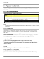
8. Control Data........................................................................ 8-1
8.1
Types of Control Data ........................................................................... 8-2
8.1.1
Unit Annunciation Relays ........................................................................ 8-2
8.1.2
RUN/IDLE Bit .......................................................................................... 8-2
8.1.3
Cyclic Communication State Tables of EtherNet/IP................................ 8-4
8.1.4
Read by ETSTAT Instruction .................................................................. 8-4
8.2
Startup Operation of Cyclic Communication .......................................... 8-5
8.3
Abnormality Judgement and Operation ................................................. 8-6
iii
Table of Contents
9. High-level Instructions ...................................................... 9-1
9.1
High-level Instructions Used for EtherNet/IP Control ............................. 9-2
9.1.1
Information Acquisition of EtherNet/IP (ETSTAT) ................................... 9-2
9.1.2
EtherNet/IP Node Status Acquisition Instruction (EIPNDST).................. 9-9
9.1.3
Cyclic Communication Start Request (EIPSTART) .............................. 9-13
9.1.4
Cyclic Communication Stop Request (EIPSTART) ............................... 9-16
9.1.5
EtherNet/IP Input Refresh (EIP_IN) ...................................................... 9-19
9.1.6
EtherNet/IP Output Refresh (EIP_OT) .................................................. 9-25
10. Data Refresh of Cyclic Communication ........................ 10-1
10.1 What is Data Refresh? ........................................................................ 10-2
10.1.1 Input Refresh T>O Direction ................................................................. 10-2
10.1.2 Output Refresh O>T Direction............................................................... 10-2
10.2 Data Refresh Method .......................................................................... 10-3
10.3 Delay Time of Transmission Data ........................................................ 10-4
10.4 Delay Time of Reception Data ............................................................. 10-5
11. Cyclic Communication Load Factor .............................. 11-1
11.1 Calculation Method of Load Factor ...................................................... 11-2
11.2 PLC Link and Ethernet Switch ............................................................. 11-5
12. Other Ethernet Communications ................................... 12-1
12.1 Performance of Other Ethernet Communications at the Time of Cyclic
Communication ............................................................................................12-2
iv
Table of Contents
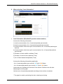
13. Communication Status Monitoring with System Web .. 13-1
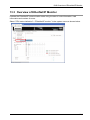
13.1 Overview of FP7 System Web ............................................................ 13-2
13.2 Starting System Web Screen .............................................................. 13-4
13.3 Overview of EtherNet/IP Monitor ......................................................... 13-5
13.4 CPU Status Indication > EtherNet/IP Monitor ...................................... 13-6
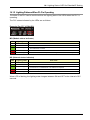
14. LED Display ..................................................................... 14-1
14.1 Lighting State of LED for EtherNet/IP Setting ...................................... 14-2
14.1.1 Lighting Patterns When Starting PLC ................................................... 14-2
14.1.2 Lighting Patterns When PLC is Operating ............................................ 14-3
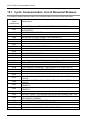
15. List of Cyclic Communication Errors ............................. 15-1
15.1 Cyclic Communication: List of Abnormal Statuses .............................. 15-2
v
Table of Contents
Contents of the Changes in EtherNet/IP Communication
Function Manual
The following functions have been added to improve the easy usability of the EtherNet/IP
function.
Use the following version for using the added functions.
FP7 CPU UNIT
FPWIN GR7(S)
: Ver.4.11 or later
: Ver.2.10 or later
Improved items of EtherNet/IP Setting Tool functions
• The following setting items have been added to the EtherNet/IP basic configuration.
This setting is available when the version of the FP7 CPU unit is Ver.4.11 or later.
- RUN/IDLE bit operation of cyclic communication
For details, refer to 8.1.2 Cyclic Communication State Tables of EtherNet/IP.
vi
1
Introduction of EtherNet/IP
Function
Introduction of EtherNet/IP Function
1.1 Introduction of EtherNet/IP Function
FP7 supports a new function "EtherNet/IP function".
This chapter describes the related names and functions, applicable models and the required
versions for using this function.
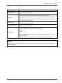
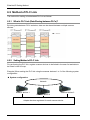
Names and Parts
(1) Operation
indicator LED
(2) LAN port
Name
Operation indicator
LED
LAN port
1-2
Description
MS
These LEDs display the operating condition of the unit.
NS
Displays the communication status of network.
For details of the lighting states of MS and NS, refer to “14.1 Lighting State of LED
for EtherNet/IP Setting“ for EtherNet/IP Setting.
Port for connecting to EtherNet LAN.
The EtherNet/IP communication is performed using the LAN port.
1.1 Introduction of EtherNet/IP Function
Models on which the EtherNet/IP function is usable
The EtherNet/IP function is available for the following four models.
Use the EDS files for each model stored in the version Ver.2.8 of GR7(s) or later.
The EDS files are also stored in the following folder.
Storage location: C:\ProgramData\Panasonic-ID SUNX Control\EIP
Note) The ProgramData folder is a hidden folder.
The EDS files can be downloaded from our website.
-
AFP7CPS31E
-
AFP7CPS41E
-
AFP7CPS31ES
-
AFP7CPS41ES
Version of FP7 CPU unit on which the EtherNet/IP function is usable
Use the following version for using the EtherNet/IP function.
-
FP7 CPU unit: Ver.4.00 or later
1-3
Introduction of EtherNet/IP Function
1-4
2
Description of EtherNet/IP
Communication Function
Description of EtherNet/IP Communication Function
2.1 What is EtherNet/IP?
EtherNet/IP (Ethernet Industrial Protocol) is an industrial multi-vendor realtime Ethernet
system for executing the communication protocol for CIP (Common Industrial Protocol) control
in an application layer on standard Ethernet.
For information on CIP, refer to the documents of ODVA.
Use the following versions for using the FP7 EtherNet/IP function.
① FP7 CPU unit: Ver.4.00 or later
② FPWIN GR7(S): Ver.2.8 or later
【Point】
- The EtherNet/IP communication and Ethernet communication (such as the communication
with GR7(S)) can be used simultaneously.
2-2
2.2 Cyclic Communication Function
2.2 Cyclic Communication Function
The cyclic communication is a function for connecting from a scanner device to an adapter
device and sending data mutually in a specified cycle after completing the connection.
The scanner device is a controller such as PLC.
The adapter device is a device such as a robot controller, encoder or IO device.
Scan list is a list that defines the connections between the scanner device and multiple
adapter devices.
A constant cycle is called RPI (Requested Packet Interval).
The side which opens the connection of the cyclic communication is called originator, and the
side which the connection is opened is called target.
The scanner device can be used as the adapter device.
2-3
Description of EtherNet/IP Communication Function
2.3 Definitions of Terms
The following terms are used in this manual and the EtherNet/IP setting tool.
Term
Description
Scan list
The scan list is the connection settings with adapter devices registered for a
scanner device.
The scanner device is connected with adapter devices according to the scan list.
EDS file
(Electric data sheet)
Originator and Target
An EDS file contains the information on the communication for registering adapter
devices in the scan list.
EDS files are provided for each product by each vendor.
The EDS files of each adapter device should be registered for constructing the scan
list with the setting tool.
The side which connects the connection of the cyclic communicationo is called
originator.
The side which the connection of the cyclic communicationo is connected is called
target.
Node numbers can be set when an adapter device is registered in the scan list.
Node number
Numbers that do not overlap are allocated in the scan list as node numbers.
Node numbers are not used in the cyclic communication, however, as each adapter
is recognized by these numbers, they are used for monitoring the communication
state of each node or controlling the start/stop of the communication.
Connection setting
The details of the connections of adapters registered in the scan list are set.
Node Name
Arbitrary node names can be given.
Device name
Connection name
This is the device name of an adapter.
The device name is registered in the EDS file.
The type of the connection manager registered in the EDS file is selected by the
name.
By selecting this, the application type (communication method) is changed.
The communication method can be selected by the application type.
The following communication methods are available;
1 : Exclusive Owner (Two-way communication)
2 : Input Only
3 : Listen Only
Application type
For a normal adapter device, select 1 (Two-way communication).
Although "Exclusive Owner" and "Input Only" are independent connections, "Listen
Only" can be connected only when either of the above connection is established,
and it will be automatically cut if the above independent connection is disconnected.
Also, it will be reconnected automatically when the above independent connection is
reconnected.
Although the FP7 can be used as an adapter, it can be connected only when "Input
Only" is selected.
2-4
2.3 Definitions of Terms
Term
Description
A method for verifying the revision of a used EDS file and the information that the
device actually used has is selected.
Compatibility check
Three verification methods are available. The default is "Follow Adapter Rule".
1 : Check
2 : Not Check
3 : Follow Adapter Rule
Either instance communication (number specifications) or tag communication (symbol
name specification) is displayed.
For connecting from a scanner to adapters, there are methods which establish the
connection by specifying numbers or by specifying symbols.
Communication method
Even when connecting by specifying symbols, numbers are assigned to packets
during the actual cyclic communication.
When selecting a connection, the methods available for the connection are displayed.
When using the FP7 as an adapter, the both methods can be used, however, in the
case of instance method, the selectable instance numbers are 100 to 199.
The transmission timing is selected from Cyclic or COS (Change of state).
However, COS depends on devices.
Send trigger
COS is basically a cyclic communication, however, it also performs transmission when
sent data changes.
The FP7 does not support COS.
COS transmission
disable time
Although COS performs transmission when sent data changes, transmission is not
performed even if the unit detects the data change within this time.
In the cyclic communication, the timeout is judged on a receiver side to send
transmission data as UDP packet.
Timeout period
The timeout period is selected from 4, 8, 16, 32, 64, 128, 256 and 512 times of RPI.
The timeout period should be 10 msec or more.
RPI can be specified for T>O direction and O>T direction separately, so each timeout
period may be different values.
Input setting (T>O)
RPI
(Requested Packet
Interval)
This is the setting for the transmission from a target to the FP7 (originator).
Set the transmission interval for the cyclic communication.Set a value within the
communication capacity of the adapter.
The usable RPI range depends on devices.
For the FP7, it is 0.5 ms to 10 s (by 0.5 ms).
2-5
Description of EtherNet/IP Communication Function
Term
Description
Select a communication method that is selectable for the selected connection.
1 : 1:1 communicaion (Point to Point)
2 : Multicast communication (Multicast)
The point-to-point communication is a 1 to 1 communication between the connection
source and destination.
Transmission packet is received by the source device or destination device only.
Other devices connected to the same HUB does not receive the transmission packet.
Connection type
In the mutlicast communication, transmission data is sent as multicast packet.
By connecting multiple sources to the same connection, single multicast packet can
be received by the multiple connection sources.
The multicast packet is basically received by all the devices connected to the same
HUB which includes the devices unrelated to the communication, and it leads to an
unnecessary communication load.
Therefore, set not to exceed 100% with the load factor caclulation of the setting tool
when using the mutlicast communication.
Also, it is recommended to use a HUB with a multicast filter.
Instance ID/Tag name
Data size
Set an instance ID or tag name according to the communication method of the
selected connection.
Set the communication data size according to the communication setting of each
adapter device.
Set this as well as changing the setting for the scanner, otherwise the communication
cannot be performed as it does not match the setting of adapters.
There are the following two refresh operations.
Refresh method
1 : Transfers the data sent to adapters to send buffers from allocated operation
memories.
2 : Transfers the data sent from adapters to allocated operation memories from
receive buffers.
The refresh method can be selected from three types, Batch, Divice and Instruction.
Parameter change
Parameters that can be changed by EDS can be changed.
PPS performance index
(Packet per sec)
This is an index of sent/received packets processed in one second.
The packet whose size is within 504 bytes is called normal packet. The packet whose
size is 505 bytes to 1444 bytes is called larget packet.
Normal packet and
large packet
The amximum communication performance varies according to the data size used for
communication.
Performance index of FP7
When the size is 504 bytes or less: Max. 10000 pps
When the size is 505 bytes or more: Max. 5000 pps
2-6
2.3 Definitions of Terms
Term
Description
Protocol used for cyclic
communication
The cyclic commuication is performed using UDP.
The used port number is 2222.
In the case of InputOnly or ListenOnly, data is sent from the target, however, a packet
called heartbeat whose size is 0 is also sent from the originator (FP7).
Heartbeat
For the RPI of this heartbeat, the value 16 times of the target is used automatically.
Heartbeat is used for confirming the continuation of connection on the target side.
It is used for detect the timeout.
Forward open
Large forward open
This is a command for opening the connection of EtherNet/IP and sent using TCP.
The used port number is 44818.
This is a command for opening the connection when sending/receiving data whose
size is larger than 504 bytes.
This bit indicates the operation state (RUN/IDLE) of a device that is sent from a
scanner or adapter duuring the cyclic communication.
RUN/IDLE bit
RUN
:1
IDLE
:0
When the RUN/IDLE bit does not become a RUN state, the adapter device may not
operate properly.
For details, refer to “8.1.2 Cyclic Communication State Tables of EtherNet/IP”.
【Note】
- Do not use "2222" and "44818" for the port numbers set to the connections of Ethernet
communication.
2-7
Description of EtherNet/IP Communication Function
2-8
3
Examples of Network
Configuration Using Cyclic
Communication Function
Examples of Network Configuration Using Cyclic Communication Function
3.1 Examples of Network Configuration Using Cyclic
Communication Function
Examples of the representative network configuration using the cyclic communication function
are as follows.
Besides the following examples, flexible configurations are available.
3.1.1 Connecting One Adapter Device or Multiple Adapter Devices to One FP7
CPU
The network is configured connecting one scanner device to multiple adapter devices as
below.
FP7 (Scanner device)
Adapter device
Adapter device
3.1.2 Linking FP7 CPUs in Multiple Blocks
The network is configured using multiple blocks of the configuration (above 2.1.1) and linking
each FP7 CPUs.
FP7 (Scanner device)
Adapter
device
3-2
Adapter
device
FP7 (Scanner device)
Adapter
device
Adapter
device
EtherNet/IP scanner by
another company
Adapter
device
4
Overview of System
Configuration Method
Overview of System Configuration Method
4.1 Overview of System Configuration Method
The system configuration is reviewed and selected by the following procedures.
1. Selection of used adapters
Select adapter devices according to applications.
2. Review of system configuration
Review the configurations of the system and network.
Besides the network configuration for the EtherNet/IP communication, review how
Ethernet communications other than the EtehrNet/IP communication is performed.
3. Selection of Ethernet switch HUB
Select a HUB considering the network configuration and the functions of HUB.
The used Ethernet switch HUB should be 100 Mpbs or more.
Some HUBs have the following functions.
Switching HUB:
Transfers only the data related to devices from the
destination.
Multicast filter
function:
Controls the multicast packet transmission to adapters or
scanners.
This is used to suppress the communication load factor
during the multicast communication of PLC link.
QOS function
(Quality of
Service):
Classifies or groups application data, and transfers data
according to the priority of each group.
The cyclic communication data of the EtherNet/IP
communication can be transferred in preference to other
Ethernet communication data.
To make the priority of the cyclic communication of the
EtherNet/IP communication higher, set the port number of
UDP to 2222.
Note)
A switching HUB can be activated in a few seconds after the power supply turns ON, however,
a switch with functions such as the multicast filter function or QOS function (Quality of
Service) is called a managed switch, and it takes several tens of seconds to be activated after
the power supply turns ON. Those differences should be considered in the system design.
4-2
5
Ethernet and EtherNet/IP
Specifications of FP7
Ethernet and EtherNet/IP Specifications of FP7
5.1 Number of Connections for Each Communication
The number of connections for each communication is limited.
Communication
Maximum number of connections
Ethernet communication
Max. 216 connections
EtherNet/IP communication
Max. 256 connections (including I/O map connections)
UCMM message communication
Max. 256 connections
*For the whole FP7, the total number of connections for Ethernet communication and
EtherNet/IP communication should be 272 or less.
Number of connections of Ethernet communication
+ EtherNet/IP communication ≤ 272 connections
5-2
5.2 Performance and Functions of FP7
5.2 Performance and Functions of FP7
For using the EtherNet/IP function on the FP7, the following functions can be used.
5.2.1 IGMP Query
With this function, the FP7 checks periodically in which host group each EtherNet/IP device is
registered on a LAN.
This function can be used when an Ethernet switch HUB with the multicast filter function and
any devices which send an IGMP query do not exist in the network.
5.2.2 TTL
TTL (Time To Live) is used to set the hierarchies of the network in which transmission packets
can live when sending multicast packets to another scanner.
5.2.3 Multicast
Data of one target can be sent to multiple originators.
5-3
Ethernet and EtherNet/IP Specifications of FP7
5-4
6
EtherNet/IP Setting Method
EtherNet/IP Setting Method
6.1 Setting Method of Cyclic Communication
This chapter describes the procedures for making the cyclic communication setting of
EtherNet/IP.
The EtherNet/IP setting is made from "EtherNet/IP Setting" of FPWIN GR7(S).
The EDS file for each EtherNet/IP device is necessary for registering the setting.
The EDS files for EtherNet IP devices are available on the site of each vendor.
Once the EDS file is registered, the registration is not required from the next time.
1) Displaying the EtherNet/IP setting screen
- Display the screen for making the EtherNet/IP setting from FPWIN GR7(S).
2) Registering EDS files
- EDS files can be registered from the device list.
3) Registering devices in the scan list
- Select a device to be connected from the device list and register it in the scan list.
- For sending data from an adapter to another scanner, add the adapter in the I/O map.
4) Making cyclic communication settings
- Change the connection setting for enabling the cyclic communication.
5) Adjusting the communication load factor
- Confirm the communication factor. Repeat "4) Make cyclic communication settings" as necessary.
The setting is complete.
6-2
6.2 How to Use EtherNet/IP Setting Tool
6.2 How to Use EtherNet/IP Setting Tool
For details of various operation methods of the EtherNet/IP tool, refer to 7. EtherNet/IP Setting
Tool.
6-3
EtherNet/IP Setting Method
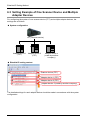
6.3 Setting Example of One Scanner Device and Multiple
Adapter Devices
For configuring the system of one scanner device (FP7) and multiple adapter devices, the
settings are as follows.
System configuration
FP7 (Scanner device)
Adapter device 1
(FP7)
Adapter device 2
(FP7)
Adapter device 3
(made by another
company)
EtherNet/IP setting content
Scanner device (FP7)
Adapter device 1 (FP7)
Adapter device 2 (FP7)
Adapter device 3 (made by another company)
The detailed settings for each adapter device should be made in accordance with the system
configuration.
6-4
6.4 Setting Example of Multiple Scanner Devices and Multiple Adapter Devices
6.4 Setting Example of Multiple Scanner Devices and
Multiple Adapter Devices
For configuring the system of multiple scanner devices (FP7) and multiple adapter devices,
the settings are as follows.
System configuration
Network
FP7 (Scanner device 1)
FP7 (Scanner device 2)
FP7 (Scanner device 3)
Adapter device Adapter device 2 Adapter device Adapter device Adapter device
1
(made by another
2
3
4
(FP7)
company)
(FP7)
(FP7)
(FP7)
EtherNet/IP setting content
Setting content of Scanner device 1
Registration data for sending data to
Scanner device 2 and Scanner device 3
Registration data for acquiring data from
Scanner device 2 and Scanner device 3
Registration data for communication with
Adapter device 1 and Adapter device 2
Make the same settings for the scanner devices 2 and 3.
6-5
EtherNet/IP Setting Method
6.5 Method of PLC Link
The method for making a link between PLCs is as follows.
6.5.1 What is PLC Link (Data Sharing between PLCs)?
By linking data between PLCs as below, data can be shared between multiple scanner
devices.
6.5.2 Setting Method of PLC Link
For performing the PLC link, register scanner devices to be linked in the scan list and data to
be linked in the I/O map.
Example) When setting the PLC link using the scanner devices 1 to 3 of the following system
configuration
System configuration
Network
Scanner device 1
Scanner device 3
Scanner device 2
Adapter devices registered for each scanner device
6-6
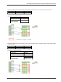
6.5 Method of PLC Link
EtherNet/IP setting: Scan list
Set the data used for the PLC link with the
scanner devices 2 and 3.
Registered information of the scanner
devices 1 to 3 used for the PLC link with
the scanner device 1. (The own unit is
registered as a reserved device.)
Adapter devices connected to the scanner
device 1
【Point】
- To easily manage the PLC link and adapter settings, make the PLC link setting as follows.
(1) First, register scanner devices including the own unit.
However, the home unit is registered as an invalid (reserved) device as it does not
communication with itself.
(2) Register the adapter device connected to the own unit after the scanner devices that
the PLC link is set.
Registering scanner devices (including the own unit) and adapter devices in this
order makes the node number of each scanner device correspond with the contents
of the scanner devices 2 and 3.
EtherNet/IP setting: I/O map
Set devices to be linked with
the scanner devices 2 and 3.
6-7
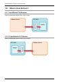
EtherNet/IP Setting Method
EtherNet/IP setting: Connection setting
Make the setting for the scanner device 3 as well.
6-8
Acquire the information on linked
devices from the scanner device 2,
and set the storage destination of
data.
7
EtherNet/IP Setting Tool
EtherNet/IP Setting Tool
7.1 Selection for Using EtherNet/IP Function
For using the EtherNet/IP function, it is necessary to set "EtherNet/IP function" to "Use" in the
Built-in ET-LAN setting dialog box.
7.1.1 How to Display the Built-in ET-LAN Setting Dialog Box
7.1.1.1 Starting Method from the Menu of GR7
Select "Options" > "FP7 Configuration" > "Built-in ET-LAN".
7.1.1.2 Starting Method from the Project Tree of GR7
Double-click "FP7 Configuration", and select "Built-in ET-LAN" and press the OK button.
7.1.1.3 Starting Method from I/O Map Setting Screen
Select "Advanced" button of the I/O map setting screen > “Built-in ET-LAN” and press the OK
button.
7-2
7.1 Selection for Using EtherNet/IP Function
7.1.2 How to Change the Built-in ET-LAN Setting Dialog Box
"Add-on" should be set to "Use" in advance for changing "EtherNet/IP Function" to "Use".
* For setting "Add-on" to "Use", the version of the CPU unit should be V3.0 or later.
* For setting "EtherNet/IP Function" to "Use", the version of the CPU unit should be Ver.4.0 or
later.
7-3
EtherNet/IP Setting Tool
If the EtherNet/IP setting is made when "EtherNet/IP Function" of the Built-in ET-LAN dialog
box is set to "Not use", the following message appears on the completion of the setting.
Selecting "Yes" changes the setting of "EtherNet/IP Function" to "Use" automatically.
* For setting "EtherNet/IP Function" to "Use", the version of the CPU unit should be Ver.4.0 or
later.
7.1.3 Restrictions and Precautions on Setting EtherNet/IP Function
Precautions on setting EtherNet/IP Function
- If the setting of "EtherNet/IP Function" is changed to "Not use", the EtherNet/IP
setting information will be cleared.
* When the setting for Add-on is changed to "Not use", the EtherNet/IP setting information will
also be cleared like a case where the EtherNet/IP function is changed.
7-4
7.2 How to Display the EtherNet/IP Setting Screen
7.2 How to Display the EtherNet/IP Setting Screen
This chapter describes how to display the EtherNet/IP setting screen.
7.2.1 Starting Method from Menu
Starting method from the menu of GR7
Select "Options" > "FP7 Configuration" > "EtherNet/IP setting".
7.2.2 Starting Method from Tree Display Area
Starting method from the project tree of GR7
Double-click "FP7 Configuration", and select "EtherNet/IP setting" and press the OK button.
7-5
EtherNet/IP Setting Tool
7.2.3 Starting Method from I/O Map Setting Screen
Starting Method from I/O Map Setting Screen
Select "Advanced" button of the I/O map setting screen > "EtherNet/IP setting" and press
the OK button.
7-6
7.3 How to Operate EtherNet/IP Setting Tool
7.3 How to Operate EtherNet/IP Setting Tool
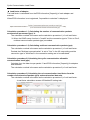
7.3.1 Structure of EtherNet/IP Setting Screen
This chapter describes the display contents of the EtherNet/IP setting screen.
Menus and icons
Switching displayed tab
I/O Map and Scan List area
Device List area
Saving/Reading EIP settings
Displayed tabs
・I/O Map Setting
・Connection Setting
・Device Property
・Device Setting
・Calculate Load Factor
Completing/Canceling
EtherNet/IP Setting
The items that can be selected by switching the display tabs vary according to the contents
selected in the I/O map and scan list area.
When selecting the originator
Select Originator.
The following screens can be displayed.
・Device Property
・Calculate Load Factor
7-7
EtherNet/IP Setting Tool
When selecting I/O map registration information
Select I/O map
registered information.
The following screens can be displayed.
・I/O Map Setting
When selecting an adapter device
Select adapter device.
The following screens can be displayed.
・Device Property
・Device Setting
When selecting the connection of an adapter device
The following screens can be displayed.
・Connection Setting
・Device Property
・Device Setting
Select connection.
7-8
7.3 How to Operate EtherNet/IP Setting Tool
7.3.2 EtherNet/IP Setting Procedure
The procedure of the EtherNet/IP setting is described below.
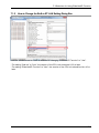
7.3.2.1 EtherNet/IP Basic Configuration
Make the EtherNet/IP basic configuration.
Procedure of displaying the screen (Start from the menu of EtherNet/IP setting)
Select "Setting" > "EtherNet/IP Basic Cofiguration".
Select from Setting.
The setting screen is displayed
after selecting "EtherNet/IP Basic
Configuration" from the menu.
Auto Allocation(*1)
LD Device Starting No.
Refresh Unit
RUN/IDLE bit operation of
cyclic communication (*2)
Cyclic Communication Start
Timing
Cyclic Communication Node
Connection Wait Time
Cyclic Communication
Connection Automatic
: Set whether to use the automatic allocation of devices or
not.
When setting "Auto Allocation" to "Yes", the device
allocation for the I/O map setting and connection setting
is automatically performed.
: Set the starting device number to be allocated at the time
of the device automatic allocation.
: Set the number of data that can be refreshed by one
scan.
: Set Normal or Limited.
: Set Auto or Manual.
: Set the period of time during which retry is repeated
without error determination.
: Set the period of time during which reconnection is retried
after the occurrence of connection timeout.
7-9
EtherNet/IP Setting Tool
Reconnection Wait Time
Message Communication
Timeout
Connection Timeout
TTL for Multicast
Multicast Address Setting
Method
No. of Multicast Addresses
Multicast Starting IP Address
IGMP Query Send Enable
IGMP Query Transmission
Interval
: Set the timeout period of message communication.
: Set the connection timeout period.
: Operation setting for performing multicast transmission as
an adapter.
: Set Auto or Specify.
: Set the number of multicast addresses.
This item is valid when Multicast Address Setting Method
is specified.
: Set the starting IP address of multicast.
This item is valid when Multicast Address Setting Method
is specified.
: Set whether to make IGMP query transmission valid or
invalid.
: Set the interval of IGMP query transmission.
*1: For allocating devices manually, set Auto Allocation to "No".
*2: For details of the operation of the RUN/IDLE bit in the cyclic communication, refer to “8.1.2
Cyclic Communication State Tables of EtherNet/IP”.
7-10
7.3 How to Operate EtherNet/IP Setting Tool
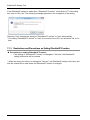
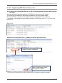
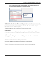
7.3.2.2 Registering EDS Files in Device List
In Device List, registered EDS files can be confirmed, deleted and new EDS files can
be added.
Only the explanation about the addition of EDS files is described in this chapter.
The EDS files for EtherNet IP devices are available on the site of each vendor.
Once the EDS file is registered, the registration is not required from the next time.
* For details of the operations other than the addition of EDS files, refer to 7.3.3 How to Use
Device List.
Device List
Method of adding EDS files (1) (Adding from the right-click menu)
If selected, the following EDS file
selection screen is displayed.
By selecting an EDS file you
want to register and "Open",
the EDS file is added.
* EDS files for EtherNet/IP devices manufactured by Panasonic cannot be added.
7-11
EtherNet/IP Setting Tool
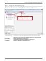
Method of adding EDS files (2) (Adding from the EtherNet/IP setting menu)
If selected, the EDS file selection
screen is displayed like the adding
method (1).
* EDS files for EtherNet/IP devices manufactured by Panasonic cannot be added.
7.3.2.3 How to Use I/O Map and Scan List
Scan list is registered in the I/O map and Scan List window.
7.3.2.3.1 Configuration of I/O Map and Scan List
The configuration of the I/O Map and Scan List window is as follows.
I/O map
Scan list
7-12
7.3 How to Operate EtherNet/IP Setting Tool
The contents displayed in the I/O Map and Scan List window are as follows.
I/O map registered information
(I/O map registration No., Tag name or Instance No.)
The background color for reserved device
(Device Setting: Invalid) changes.
Node No., Node information and
Connection information
7-13
EtherNet/IP Setting Tool
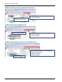
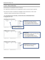
7.3.2.3.2 Registering Adapter Devices
Adapter devices can be registered by the following three operations.
How to add adapter devices
[Adding method (1)]
Select device name (EDS) from Device
List, and then add it to the end of Scan
List from the menu.
[Adding method (2)]
Drag and drop a target device name (EDS) with a mouse.
It can be inserted into an arbitrary place.
[Adding method (3)]
Right-click on device name (EDS) of
Device List, and then add it to the end of
Scan List.
* If an adapter device is dragged and dropped to a node that is already registered, it will be
registered after the node.
* For details of the operations other than registering adapter devices, refer to 7.3.4.1 Editing
Scan List.
7-14
7.3 How to Operate EtherNet/IP Setting Tool
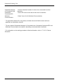
7.3.2.4 How to Use “Device Setting” Tab
Settings are made from the Device Setting tab after registering an adapter device.
Selecting an adapter device
selects Device Setting tab
automatically.
Valid/Invalid Flag
Node Name
IP Address
: Set whether to make the communication with nodes valid or invalid.
When this is set to Invalid, the adapter is treated as a reserved device.
: Specify the node name of the device.
The specified node name is displayed in the scan list.
: Set the IP address of a destination device.
7-15
EtherNet/IP Setting Tool
7.3.2.5 How to Use "Connection Setting" Tab
Set from the Connection Setting tab.
Selecting a connection selects
Connection Setting tab automatically.
Common Information
Node Name
: The node name where the connection is registered is displayed.
Device Name
: The device name where the connection is registered is displayed.
Connection Name
: Set from the connection settings registered in EDS files.
Application Type
: The application type of a selected connection setting is displayed.
Compatibility Check
: Set the compatibility check of models to "Check", "Not Check" or
"Follow Adapter Rule".
7-16
7.3 How to Operate EtherNet/IP Setting Tool
COS Transmission Disable
: Transmission disable time (RPI of input information x 1/4) is
displayed when "Input Send Trigger" is set to "Change of State
(COS)".
Communication Method
: The communication method (Instance or Tag) of the currently
specified connection setting is displayed.
Timeout Period
: Set the communication timeout period of cyclic
communication.
Selectable items
Input Send Trigger
Parameter Setting
RPI x 4 / RPI x 8 / RPI x 16 / RPI x 32
RPI x 64 / RPI x 128 / RPIx 256 / RPI x 512
: Set a data communication method with scanners.
: The following screen is displayed by pressing the "Parameter
Setting" button. Parameters defined in EDS files can be set.
Parameter information
defined in EDS files can be
set.
* Parameter information that
can be changed in the EDS
file is displayed.
7-17
EtherNet/IP Setting Tool
7.3.2.5.1 Device Allocation
Set the device to be allocated to Send or Receive.
Up to eight device allocations can be registered for send or receive of each connection.
The maximum number of words that is available for device allocation is 16kw in total.
(Allocation cannot be performed beyond 16384 words.)
* For allocating devices manually, set Auto Allocation of EtherNet/IP Basic
Configuration to "No".
Adding device allocation
Add button:
Adds device allocation settings.
* For the setting method, refer to
"Setting Method of Device Allocation".
Already registered
information is displayed.
Editing device allocation
Edit button:
Corrects the currently selected setting
that is already registered.
* For the setting method, refer to
"Setting Method of Device Allocation".
Deleting device allocation
Delete button:
Deletes the currently selected
device allocation setting.
7-18
7.3 How to Operate EtherNet/IP Setting Tool
Setting method of Device Allocation
Register button:
Registers the current setting.
Cancel button:
Cancels the setting.
No
: A registration number is displayed.
Device Division
: Select the set device division from G (Global) or L (Local).
Device Type
: Select Device Type from WX, WY, WR, WL, DT and LD.
Device No.
: Set the starting number of the device.
PB No.
: Set the PB number of the local device.
The setting is necessary when Device Division is set to L.
Data Size
: Set a data size secured from the device number.
Offset
: Set the destination of allocation of sent or received data with offsets.
7-19
EtherNet/IP Setting Tool
7.3.2.6 Adding I/O Map Registered Information
Edit the I/O map to be operated as an adapter.
How to add I/O map
Select "I/O Map - Scheduled
connections ...", and select "Add
I/O Map" from the right-click menu.
* For details of the operation other than adding I/O maps, refer to“7.3.4.2 Editing I/O Map“.
7-20
7.3 How to Operate EtherNet/IP Setting Tool
7.3.2.7 Setting I/O Map Registered Information
Set I/O map registered information.
Selecting I/O map registered
information selects I/O Map
Setting tab automatically.
I/O Map No.
: The I/O map number currently being set.
Communication
Method
: Select a communication method with another scanner from Instance
or Tag.
Instance ID
: Set an instance ID.
This set when Communication Method is set to Instance.
Tag Name
: Set a tag name.
This set when Communication Method is set to Tag.
Data Size
: Set the data size to be sent to another scanner.
Refresh Method
: Select the setting method for sent data from Batch, Divide and
Instruction.
Standby Refresh
Cycle Setting
: Set a setting cycle of sent data.
Device Allocation
: Set the device to be allocated to sent data.
7-21
EtherNet/IP Setting Tool
Scheduled Number
of Connected Units
: Set the scheduled number of units to be connected from other
scanners.
Scheduled
Connected RPI
: Set an RPI value to be used at the time of connection.
Multicast
Communication
: Select Yes or No for Multicast Communication.
* The specified instance ID (or tag name) and data size should be the same as those
specified in a destination scanner.
* The set values of Scheduled Number of Connected Units, Scheduled Connected RPI and
Multicast Communication are used for calculating a communication load factor.
* For information on the setting procedure of device allocation, refer to “7.3.2.5.1 Device
Allocation”.
7-22
7.3 How to Operate EtherNet/IP Setting Tool
7.3.2.8 How to Use "Calculate Load Factor" Tab
Overview of the calculation of load factor
The load factor is the ratio of the number of actually used packets to the maximum number of
packets which the EtherNet/IP unit can send/receive in one second by cyclic communication.
Packets other than by cyclic communication or unnecessary received packets are not
considered for calculating the load factor.
Determines the check box for selecting whether to enable or disable the IGMP snoop function
for HUB, and calculates load factors.
Reserved nodes are not included in the calculation of load factor.
The adapter communication load factor is displayed only when an EDS file exists.
7.3.2.8.1 Display of Load Factor Calculation
Selecting originator selects Calculate
Load Factor tab automatically.
Whole Unit Communication
Load Factor
: The sum of the load factors of the whole unit is displayed.
I/O Map Communication
Load State
: The load factor calculated from the I/O map setting is
displayed.
Scan List Communication
Load State
: The load factor calculated from the connection setting is
displayed.
HUB Switch IGMP Snoop
Function
: Set whether to make this function valid or invalid for
calculating the load factor.
When this is set to Invalid, the title is displayed in red.
* When the load factor is 100% or more, it is displayed in red.
When the adapter load factor is 100% or more, the title is displayed in red.
When the Multicast is enabled, the title background is displayed in yellow.
7-23
EtherNet/IP Setting Tool
Whole Unit Communication Load Factor
Unit Load Factor
: The communication load factor (%) of the whole unit is displayed.
Whole Unit (pps)
: The communication volume per second used for the whole system(*1)
is displayed in pps.
Whole Unit (Mbps)
: The communication volume per second used for the whole system is
displayed in Mbps.
Receive (pps)
: The communication volume per second in the receiving direction used
for the whole system(*2) is displayed in pps.
Send (pps)
: The communication volume per second in the sending direction used
for the whole system(*3) is displayed in pps.
*1: The sum of reception (pps) and transmission (pps)
*2: The sum of I/O map communication output T>O (pps) and scan list input T>O (pps)
*3: The sum of I/O map communication input O<T (pps) and scan list output O<T (pps)
I/O Map Communication Load Factor State
Load Factor Breakdown
: The breakdown of the load factor for each tag name [instance
name] is displayed.
Tag Name [Instance ID]
: Tag names [instance names] are displayed.
Scheduled Number of
Connected Units
: The scheduled number of connected units is displayed.
Output (T>O)
Scheduled Connected
RPI
: Scheduled connected RPI (communication interval) is
displayed.
MultiCast
: When communication data is sent through multicasting, '•' is
displayed.
(pps)
: The communication volume (pps) calculated by the output
(T>O) scheduled connected RPI is displayed.
Input (O>T)
Scheduled Connected
RPI
: Values calculated by multiplying output (T>O) RPI by 16 is
displayed. (*1)
(pps)
: Communication volumes (pps) calculated by multiplying output
(T>O) RPI by 16 is displayed.
*If the value calculated by multiplying RPI (ms) by 16 is 10s or more, the RPI is calculated
as 10s.
Scan List Communication Load State
Load Factor Breakdown
: The breakdown of the unit load factor for each adapter is
displayed.
Adapter Load Factor
: The load factor calculated from the communication band
defined in EDS files of each adapter and scanner is displayed.
Node Name
: Node names of adapters and scanners are displayed.
Connection Name
: Connection names of adapters and scanners are displayed.
7-24
7.3 How to Operate EtherNet/IP Setting Tool
Input (T>O)
RPI
: The RPI (communication interval) in the receiving direction of
connection settings is displayed.
COS
: For the connection setting in which "Input Send Trigger" is set to
"Change of State", '•' is displayed.
MultiCast
: For the connection setting in which "Connection Type" is set to
"Multicast", '•' is displayed.
(pps)
: The communication volume (pps) per second in the receiving
direction is displayed.
Output (O>T)
RPI
: The RPI (communication interval) in the sending direction of
connection settings is displayed.
(pps)
: The communication volume (pps) per second in the sending
direction is displayed.
HUB Switch IGMP Snoop Function
Select whether to make this function valid or invalid for calculating the load factor.
When selecting "Invalid", "HUB Switch IGMP Snoop Function" is displayed in red.
Even when you use a switch equipped with the IGMP snoop function, this function should
be set to "Valid".
* For outputting IGMP queries to FP7, "7.3.2.1 EtherNet/IP Basic Configuration" should be set.
* If the adapter load factor exceeds 100% when setting the multicast communication, change
the set value of RPI longer or use a HUB that the IGMP snoop function is enabled.
7-25
EtherNet/IP Setting Tool
7.3.3 How to Use Device List
In Device List, registered EDS files can be confirmed, deleted and new EDS files can be
added.
The EDS files for EtherNet IP devices are available on the site of each vendor.
Once the EDS file is registered, the registration is not required from the next time.
* For details of how to add EDS files to Device List, refer to 7.3.2.2 Registering EDS Files in
Device List.
Device List
Deleting a regsitered EDS file (Deleting from the right-click menu)
Select a device you want
to delete, and select from
the right-click menu.
* EtherNet/IP devices manufactured by Panasonic cannot be deleted.
Deleting a regsitered EDS file (Deleting from the EtherNet/IP setting menu)
Select a device you want
to delete, and select from
the right-click menu.
* EtherNet/IP devices manufactured by Panasonic cannot be deleted.
7-26
7.3 How to Operate EtherNet/IP Setting Tool
Rearranging EDS files
By Vendor button:
Sorts registered EDS files by vendor.
By Device button:
Sorts registered EDS files by device type.
Searching EDS files
Find button:
Displays only the EDS files found by
pressing the button after entering a
retrieval word.
Display All button:
Clears retrieval results and displays all
registered EDS files.
7-27
EtherNet/IP Setting Tool
7.3.4 How to Use I/O Map and Scan List Screen
In this chapter, operation methods of I/O map and scan list screen are described.
For details of screen structures, refer to 7.3.2.3.1 Configuration of I/O Map and Scan List.
7.3.4.1 Editing Scan List
Edit the scan list.
* For details of how to add adapter devices to the scan list, refer to 7.3.2.3.2 Registering
Adapter Devices.
Editing adapter devices (deleting, moving and copying)
Operate by Edit menu and Menu bar after selecting a node.
The following operations are
available by the right-click
menu of the node.
・Delete
・Copy
・Cut
・Paste
The following operations are available on Scan List.
Operating adapter devices
Plural selection (Range selection):
Select an adapter device while pressing the Shift key.
Plural selection (Optional selection):
Select an adapter device while pressing the Ctrl key.
Move:
Drag an adapter device to a destination with a mouse.
Move (Plural):
Select multiple adapters with the Shift or Ctrl key, and
drag them to a destination.
* Operate while pressing the Shift or Ctrl key.
7-28
7.3 How to Operate EtherNet/IP Setting Tool
Adding connections to adapter devices
After selecting a connection of an
adapter device, add it by Edit menu.
Add a connection by the right-click
menu of the adapter device.
Deleting connections of adapter devices
After selecting a connection of an
adapter device, delete it by Edit menu.
Delete a connection you want to delete
by the right-click menu.
7-29
EtherNet/IP Setting Tool
Rearrange Scan List
Rearrange Scan List from the selected node.
After selecting "Rearrange Scan List", the
setting dialog is displayed.
Rearrange the list from the node No. (100) and
IP address (192.168.1.100) as starting
numbers.
Target of rearrangement:
・Node No. of Scan List [2]
・Node No. of Scan List [3]
・Node No. of Scan List [4]
7-30
7.3 How to Operate EtherNet/IP Setting Tool
Reallocating devices (I/O Map)
Reallocate Device Setting from the selected I/O
map.
(Target: Connections of I/O Map)
After selecting "Reallocate Device", the setting
dialog is displayed.
Allocate devices from the LD device starting No.
(1000) as a starting number.
Target of reallocation:
・Connection of I/O map [2]
・Connection of I/O map [3]
・Connection of I/O map [4]
7-31
EtherNet/IP Setting Tool
Reallocating devices (Adapter devices)
Reallocate Device Setting from the
selected adapter device.
(Target: Connections of adapter devices)
After selecting "Reallocate Device", the
setting dialog is displayed.
Allocate devices from the LD device starting No.
(100) as a starting number.
Target of reallocation:
・Node No. of Scan List [2]
・Node No. of Scan List [3]
・Node No. of Scan List [4]
7-32
7.3 How to Operate EtherNet/IP Setting Tool
7.3.4.2 Editing I/O Map
Edit the I/O map to be operated as an adapter.
* For details of how to add I/O maps, refer to 7.3.2.6 Adding I/O Map Registered Information.
Deleting I/O map
Select "Delete I/O Map" by the
right-click menu of the I/O map
to be deleted.
7.3.4.3 When EDS Files are Unregistered
When EDS files of adapter devices registered in the scan list are not registered in the device
list, they are shown on the scan list as below.
When the EDS file of an
adapter device is unregistered
7.3.5 How to Use Device Property Setting
In this chapter, the Device Property window is described.
7-33
EtherNet/IP Setting Tool
7.3.5.1 Device Property Setting
The Device Property can be displayed by the following three methods.
Displaying Device Property tab
[Operation method (1)]
Display the device property tab of a selected node by
Edit menu.
[Operation method (2)]
Display the device property tab of a selected
node.
[Operation method (3)]
Display the device property tab of a
selected device name.
7-34
7.3 How to Operate EtherNet/IP Setting Tool
Device Property
Displays the information on the EDS file corresponding to a selected node or device name.
Icons can be
changed.
Displays the EDS file.
Changes made on the
display are invalid.
Icon
: The device icon is displayed.
When EDS files are unregistered, "?" is displayed.
Device Name
: Displays the device name.
Description
: Displays the text.
Creation date
: Displays the creation date of an EDS file.
Update date
: Displays the last update date of an EDS file.
File revision
: Displays the file revision.
Vendor name
: Displays the vendor name.
Device type
: Displays the device type.
Product code
: Displays the product code.
Revision
: Displays the revision.
Catalog
: Displays the catalog number.
* The displayed contents for the device name to catalog are the information defined in the
corresponding EDS file.
7-35
EtherNet/IP Setting Tool
7.3.6 How to Use "Save Setting" and "Read Setting"
This function is used to save the settings on the EtherNet/IP setting screen to a file.
Saved settings can be read as necessary.
7-36
7.3 How to Operate EtherNet/IP Setting Tool
7.3.7 Migration of Device Database
Registration information of EDS files can be exported or imported.
7.3.7.1 Export of Device Database
The procedure of the export function is described below.
1. Select "Export Device Data Base".
Select from the "EDS File" menu or the light-click menu of the device list.
7-37
EtherNet/IP Setting Tool
2. Select an output destination of the device database.
If you want to create a new folder, create a folder by "Create a New Folder".
* As registered EDS files, icon files, device database files are output to the
selected folder, specify an empty folder if you specify an arbitrary storage
destination.
3. The export is complete.
7-38
7.3 How to Operate EtherNet/IP Setting Tool
7.3.7.2 Import of Device Database
The procedure of the import function is described below.
Note)
Once the import is performed, the registered information of the device list will be overwritten
by the contents of the imported device database. We recommend to export and store the
registered information before performing the import.
1. Select "Import Device Data Base".
Select from the "EDS File" menu or the light-click menu of the device list.
7-39
EtherNet/IP Setting Tool
After the selection, the following notes on the import operation is displayed.
If no problem, select "OK". Otherwise, select "Cancel".
Note)
Always save the EtherNet/IP setting before import.
As the EtherNet/IP setting is finished after importing database, the information
that is still in the middle of change operation will be cleared.
2. Select an import folder.
Specify the folder in which the device database to be imported is stored.
3. Reactivate the EtherNet/IP setting screen.
As the EtherNet/IP setting is automatically finished after selection "OK", display
the EtherNet/IP setting screen again.
4. The import is complete.
7-40
7.3 How to Operate EtherNet/IP Setting Tool
When the EtherNet/IP screen is displayed again, the registered contents of the
device list has been changed to the imported contents.
Added information
by importing
database
7.3.7.3 When You Want to Restore the Registration Information Before Import
If you need to restore the previous registration information after the completion of import,
import folders stored in the following folder.
* AppData (Application Data for Windows XP) folder is a hidden folder.
For Windows7
C:\Users\(Account name of PC)\AppData\Roaming\Panasonic-ID SUNX Control\EIP\backup
For WindowsXP
C:\Documents and Setting\(Account name of PC)\Application Data\Panasonic-ID SUNX
Control\EIP\backup
This folder is backup data before reflecting imported data.
If the import operation fails, registration information will not be backed up.
When the information has been backed up manually, import the backed-up folder.
7-41
EtherNet/IP Setting Tool
7-42
8
Control Data
Control Data
8.1 Types of Control Data
There are two types of control data, unit annunciation relays (from X6B) and communication
state tables.
8.1.1 Unit Annunciation Relays
There are the following unit annunciation relays.
Annunciation
device
Description
X6B
EtherNet/IP preparation done = 1, Other s = 0
X6C
Cyclic communication: All nodes communicating normally =1, Others = 0
X6D
Cyclic communication: All nodes stop =1, Others = 0
X6E
Communication abnormal node exists = 1, None = 0
X6F
EtherNet/IP Start/Stop controllable = 1, Uncontrollable = 0
Note)
Unit annunciation relay numbers vary according to the base numbers of the unit I/O map
registration.
8.1.2 RUN/IDLE Bit
The RUN/IDLE bit indicates the operation state of a device that is sent from a scanner or
adapter during the cyclic communication. 1 is sent for the RUN state, and 0 is sent for the
IDEL state.
When the operation state of a scanner is IDLE, an adapter device connected to that scanner
may not operate normally.
As for adapter devices, it may not be sent depending on the settings of EDS files.
Operation of FP7
On the FP7, the RUN/IDLE bit becomes the run state in the following cases
The condition that the RUN/IDLE bit becomes the RUN state varies according to the setting of
"RUN/IDLE bit operation of cyclic communication" of the EtherNet/IP basic configuration
(Normal or Limited).
• Normal
When the following two conditions are met, it becomes the RUN state.
In other conditions, it is in the IDLE state.
(1) The FP7 operation mode is RUN mode.
(2) It is communicating with all nodes registered in the scan list except the FP7 normally.
8-2
8.1 Types of Control Data
• Limited
A value corresponding to the FP7 operation mode is set regardless of the communication
state with adapters registered in the scan list.
RUN mode
: RUN
PROG mode : IDLE
Note)
Only the normal operation is available when the version of the FP7 CPU unit is older than
Ver.4.10.
Method of selecting RUN/IDLE bit operation of cyclic communication
Set "RUN/IDLE bit operation of cyclic communication" in the EtherNet/IP basic configuration
according to the use situation.
• Normal
Select for performing the EtherNet/IP communication with all adapters registered in the scan
list.
Note)
When communication cannot be performed with all adapter devices (except FP7) registered in
the scan list normally with this setting, there are cases where the adapter devices that is
communicating normally cannot operate normally as the RUN/IDLE bit is sent as IDLE.
• Limited
Select this setting for the use in situations where a part of devices in the scan list are activated
and the others are stopped such as a test operation.
* e.g. Communication cannot be performed because the power supply of an adapter is OFF.
Besides this setting, the similar operation can be performed by the following method.
(1) Register only the adapter devices that you want to activate in the scan list.
(2) Set the other adapter devices in the scan list to be disabled.
8-3
Control Data
8.1.3 Cyclic Communication State Tables of EtherNet/IP
There the following types of cyclic communication state tables.
Table type
Description
Cyclic communication
registration node table
Bit corresponding to the node number that the connection is regsitered =1,
Invalid node = 0
Cyclic communication
normal node table
When the first refresh is complete after connection establishment = 1, Other
states = 0
Cyclic communication stop
node table
Bit corresponding to the node to be stopped when the stop request
processing is complete = 1, Others = 0
Cyclic communication
abnormal node table
Node that the cyclic commuication error occurs =1, Others = 0
Cyclic communication:
RUN/IDLE bit monitor
Bit corresponding to the node number of FP7 that connection is registered.
When the following two conditions are met, it turns ON (1).
In other conditions, it turns OFF (0).
・Communicating with the target node (FP7) normally.
・Communicating with all nodes except FP7 normally when the target node
(FP7) is in RUN mode.
Note)
The communication condition with the FP7 node connected to the source is
not reflected.
8.1.4 Read by ETSTAT Instruction
Communication state tables can be read by the ETSTAT instruction and monitored.
For details, refer to “9.1.1 Information Acquisition of EtherNet/IP (ETSTAT)”.
8-4
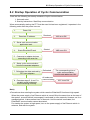
8.2 Startup Operation of Cyclic Communication
8.2 Startup Operation of Cyclic Communication
There are the following two startup methods of cyclic communication.
1. Automatic start
2: Start by Instructions: Start/Stop communication
When automatically starting the FP7 that the scan list has been registered, it operates in the
following order after the power turns on.
1:
Power ON
2:
Resolves IP address.
Resolved.
X62 turns ON.
3: Starts each communication
application task.
4:
Starts EtherNet/IP task.
Started.
X6B turns ON.
5: Connects to adapter devices
according to the scan list.
6: Starts cyclic communication
from the connected adapters.
7: Refreshes the data received by
FP7 from adapters.
8: Executes steps 5, 6 and 7 in
parallel and all nodes are
communicating normally.
Refreshed.
The corresponding bits of
cyclic communication
normal node tables turn ON.
All nodes are
communicating.
X6C turns ON.
Note)
• Precautions when starting the system which uses the EtherNet/IP function at high speed:
When the power supply of an Ethernet switch is turned ON at the same time as the start of
the system, a normal switch (unmanaged) is activated in a few seconds. However, as for a
managed switch, it takes several tens of seconds. Until the switch is activated, the
EtherNet/IP communication cannot be started.
For starting the system at high speed, turn on the power supply of the Ethernet switch in
advance, and start the system.
8-5
Control Data
8.3 Abnormality Judgement and Operation
Abnormality judgement is performed on the following contents.
Abnormality judgement
Details
Connection timeout period
The timeout period when FP7 sends a forward open
command and connects to adapter devices.
When a response to the forward open command is not
returned within the set time, it determines that the timeout
occurs.
By setting this period short, it is possible to make the
reconnection time shorter when the power is turned on
again.
Cyclic communication start
wait time
(Abnormality judgement
when starting cyclic
communication)
If connection is not established when starting the cyclic
communication, the operation is retried after the connection
timeout period, however, the communication abnormal
node flag is set after the elapse of this time.
The abnormality judgement is not performed before this
time passes.
The reconnection is retried automatically even after the
determination of the communication abnormal node.
Cyclic communication
abnormality judgement time
(Abnormality judgement after
connection)
When the timeout occurs during the transmission from an
adapter while the cyclic communication is performed
properly, the reconnection is retried automatically, however,
it judges as a communication error when the reconnection
is not established within this set time.
The reconnection is retried automatically even after the
determination of the communication abnormal node.
By setting this time short, it is possible to judge
communication errors quickly.
8-6
9
High-level Instructions
High-level Instructions
9.1 High-level Instructions Used for EtherNet/IP Control
High-level instructions that can be used for EtherNet/IP control are as follows.
List of instructions
Instruction
Application
ETSTAT
Information acquisition of EtherNet/IP
EIPNDST
EtherNet/IP node status acquisition instruction
EIPSTART
Cyclic communication start request
EIPSTOP
Cyclic communication stop request
EIP_IN
EtherNet/IP input refresh
EIP_OT
EtherNet/IP output refresh
9.1.1 Information Acquisition of EtherNet/IP (ETSTAT)
Instruction format
R0
ETSTAT
“EIP”
“ALL”
DT0
S1
S2
D
Note) A target unit for the instruction is specified with UNITSEL beforehand.
Operation unit (i)
There is no operation unit.
List of operands
Operand
Description
S1
Specify the type to be read with the starting address or a character constant.
S2
Specify the target to be read with the starting address or a character constant.
D
Specify the starting address of destination.
Available devices (●: Available)
16-bit device
32-bit device
WS
TS
CS
Real
number
Integer
Operand
WX
S1
S2
D
9-2
WY
WR
WL
● ● ● ●
● ● ● ●
● ● ● ●
SD
DT
LD
● ●
● ●
● ●
UM
WI
WO
TE
CE
IX
K
U
H
SF
DF
String
Index
modifier
""
●
●
●
●
●
9.1 High-level Instructions Used for EtherNet/IP Control
Processing
• Reads the parameter information or status information specified by [S1] and [S2], and stores
it in the area starting with [D].
• The number of words in the storage area varies according to the type of read data and the
target.
Precautions during programming
• When specifying a device for an operand in which character constant can be specified, set
string data beforehand with SSET instruction.
• When specifying string data, the number of characters should not execeed 256.
• Upper and lower case characters can be used for operands which character constant can be
specified.
("Abcd", "ABCD" and "abcd" are synonymous, however, the file names are differentiated.)
• A target unit for the instruction is specified with UNITSEL beforehand.
• This instruction is not available in interrupt programs.
Operands [S1] [S2] settings
Setting
item
Settings
Read type
S1
Read target
S2
Read
destination
D
For specifying the read of the EtherNet/IP
communication state
Specify "EIP".
For specifying the communication state of
EtherNet/IP
Specify "ALL" or "ALL +
Number".
For specifying the cyclic communication
registration node table
Specify "NODE".
For specifying the cyclic communication
normal node table
Specify "NORMAL".
For specifying the cyclic communication stop
node table
Specify "STOP".
For specifying the cyclic communication
abnormal node table
Specify "ERR".
For specifying the RUN/IDLE bit monitor (PLC
standby flag)
Specify "PLC".
Specify the destination device address to which the state is read out.
Restrictions on combinations of operands [S1] and [S2]
"A" in the table below indicates the available combinations. An operation error occurs when
other combinations are specified.
S2
S1
EIP
ALL
NODE
NORMAL
STOP
ERR
PLC
○
○
○
○
○
○
9-3
High-level Instructions
Read content 1 (In the case of S1; "EIP", S2; "ALL" or "ALL + Number": 1 to 81 words)
Name
No. of
words
Max. registration node number
Cyclic communication registration node table
Cyclic communication normal node table
Cyclic communication stop node table
Cyclic communication abnormal node table
RUN/IDLE bit monitor (PLC standby flag)
Description
Registered maximum node number
1
0 to 16
(*1) (*2)
0 to 16
(*1) (*2)
0 to 16
(*1) (*2)
0 to 16
(*1) (*2)
0 to 16
(*1) (*2)
Node that connection is registered
Node that the cyclic communication is performed
normally
Node that the cyclic communication stops
Node that the cyclic communication error occurs
RUN/IDLE bit monitor of 32-bit header
Read content 2 (In the case of S1; "EIP", S2; "NODE": 1 to 17 words)
Name
No. of
words
Max. registration node number
Cyclic communication registration node table
Description
1
Registered maximum node number
0 to 16 (*1)
Node that connection is registered
Read content 3 (In the case of S1; "EIP", S2; "Normal": 1 to 17 words)
Name
Max. registration node number
Cyclic communication normal node table
No. of
words
1
0 to 16 (*1)
Description
Registered maximum node number
Node that the cyclic communication is performed
normally
Read content 4 (In the case of S1; "EIP", S2; "STOP": 1 to 17 words)
Name
Max. registration node number
Cyclic communication stop node table
No. of
words
1
0 to 16 (*1)
Description
Registered maximum node number
Node that the cyclic communication stops
Read content 5 (In the case of S1; "EIP", S2; "ERR": 1 to 17 words)
Name
Max. registration node number
Cyclic communication abnormal node
table
No. of
words
1
0 to 16 (*1)
Description
Registered maximum node number
Node that the cyclic communication error occurs
Read content 6 (In the case of S1; "EIP", S2; "PLC": 1 to 17 words)
Name
Max. registration node number
RUN/IDLE bit monitor of 32-bit header
9-4
No. of
words
1
0 to 16 (*1)
Description
Registered maximum node number
RUN/IDLE bit monitor of 32-bit header
9.1 High-level Instructions Used for EtherNet/IP Control
*1: The number of words varies according to the registered maximum node number.
Max. node
number
No. of valid
words
0
0
1 to 16
1
17 to 32
2
33 to 48
3
49 to 64
4
:
:
225 to 239
15
241 to 256
16
*2: When specifying "ALL + Number" for S2, the number of valid words is the specified
number.
The numbers are 1 to 16.
Allocation of bit numbers and node numbers of each table and monitor
Correspondence table of node numbers
Bit No.
15
Node
No.
16
:
:
Node
No.
256
14
13
12
11
10
9
8
7
6
5
4
3
15
14
13
12
11
10
9
8
7
6
5
4
255
254
253
252
251
250
249
248
247
246
245
244
2
3
243
1
0
2
1
242
241
9-5
High-level Instructions
Setting example
Example 1) When specifying the reading of EtherNet/IP communication state
S1
S2
D
"EIP"
"ALL"
DT20
Value
DT20
15
DT21
0111 1111 1111 1111
Max. registration node number
Cyclic communication registration node table (Node nos. 1 to 16)
DT22
0111 1000 1011 1111
Cyclic communication normal node table (Node nos. 1 to 16)
DT23
0000 0111 0100 0000
Cyclic communication stop node table (Node nos. 1 to 16)
DT24
0000 0000 0100 0000
Cyclic communication abnormal node table (Node nos. 1 to 16)
DT25
0000 0000 0000 1111
RUN/IDLE bit monitor (PLC standby flag) (Node nos. 1 to 16)
Example 2) When specifying the reading of EtherNet/IP communication state
S1
S2
D
"EIP"
"ALL"
DT20
Value
DT20
0
Max. registration node number
Example 3) When specifying the reading of cyclic communication registration node table
S1
S2
D
"EIP"
"ALL+2"
DT20
Value
9-6
Max. registration node number
DT20
15
DT21
1st word
Cyclic communication registration node table (Node nos. 1 to 16)
DT22
2nd word
Cyclic communication registration node table (Node nos. 17 to 32)
DT23
1st word
Cyclic communication normal node table (Node nos. 1 to 16)
DT24
2nd word
Cyclic communication normal node table (Node nos. 17 to 32)
DT25
1st word
Cyclic communication stop node table (Node nos. 1 to 16)
DT26
2nd word
Cyclic communication stop node table (Node nos. 17 to 32)
DT27
1st word
Cyclic communication abnormal node table (Node nos. 1 to 16)
DT28
2nd word
Cyclic communication abnormal node table (Node nos. 17 to 32)
DT29
1st word
RUN/IDLE bit monitor (PLC standby flag) (Node nos. 1 to 16)
DT30
2nd word
RUN/IDLE bit monitor (PLC standby flag) (Node nos. 1 to 32)
9.1 High-level Instructions Used for EtherNet/IP Control
Example 4) When fixing the number of valid words (The communication states of node numbers 1 to 16 are
displayed.)
S1
S2
D
"EIP"
"ALL+1"
DT20
Value
Max. registration node number
DT20
100
DT21
1st word
DT22
1st word
Cyclic communication normal node table (Node nos. 1 to 16)
DT23
1st word
Cyclic communication stop node table (Node nos. 1 to 16)
DT24
1st word
Cyclic communication abnormal node table (Node nos. 1 to 16)
DT25
1st word
RUN/IDLE bit monitor (PLC standby flag) (Node nos. 1 to 16)
Cyclic communication registration node table (Node nos. 1 to 16)
Example 5) When specifying the reading of cyclic communication registration node table
S1
S2
D
"EIP"
"NODE"
WX100
Value
Max. registration node number
WX100
40
WX101
1111 1111 1111 1111
Cyclic communication registration node table (Node nos. 1 to 16)
WX102
1111 1111 1111 1111
Cyclic communication registration node table (Node nos. 17 to 32)
WX103
0000 0000 1111 1111
Cyclic communication registration node table (Node nos. 33 to 48)
Example 6) When specifying the reading of cyclic communication normal node table
S1
S2
D
"EIP"
"NORMAL"
WY100
Value
WY100
7
WY101
0000 0000 0111 1111
Max. registration node number
Cyclic communication normal node table (Node nos. 1 to 16)
Example 7) When specifying the reading of cyclic communication stop node table
S1
S2
D
"EIP"
"STOP"
WR100
Value
WR100
8
WR101
0000 0000 1111 1111
Max. registration node number
Cyclic communication stop node table (Node nos. 1 to 16)
9-7
High-level Instructions
Example 8) When specifying the reading of cyclic communication abnormal node table
S1
S2
D
"EIP"
"ERR"
WR100
Value
WR100
5
WR101
0000 0000 0000 1000
Max. registration node number
Cyclic communication abnormal node table (Node nos. 1 to 16)
Example 9) When specifying the reading of RUN/IDLE bit monitor (PLC standby flag)
S1
S2
D
"EIP"
"PLC"
WR2000
Value
Max. registration node number
WR2000
50
WR2001
1111 1111 1111 1111
RUN/IDLE bit monitor (Node nos. 1 to 16)
WR2002
1111 1111 1111 1111
RUN/IDLE bit monitor (Node nos. 17 to 32)
WR2003
1111 1111 1111 1111
RUN/IDLE bit monitor (Node nos. 33 to 48)
WR2004
0000 0000 0000 0011
RUN/IDLE bit monitor (Node nos. 49 to 64)
Flag operation
Name
Description
Set when the read area is out of the range.
Latest error
(S7)
Hold error
(S8)
Set when the read type (S1) is set to an item other than "IPv4", "IPv6", "FTPc", "HTTPc",
"SMTPc" or "EIP"
Set when the target to be read (S2) is set to an item other than "MAC", "CONNECT", "IDx",
"LOGx", IDALL", "LOGALL", "ALL", "NODE", "NORMAL", "STOP", "ERR" or "PLC".
Set when a combination other than the combinations listed in the restrictions on combination is
specified for the type (S1) and target (S2) to be read.
Set when the unit specified by UNITSEL is not an Ethernet unit.
Set when executed in an interrupt program.
9-8
9.1 High-level Instructions Used for EtherNet/IP Control
9.1.2 EtherNet/IP Node Status Acquisition Instruction (EIPNDST)
Instruction format
R0
EIPNDST
U1
DT100 DT2000
S
D1
D2
Note) A target unit for the instruction is specified with UNITSEL beforehand.
Operation unit (i)
There is no operation unit.
List of operands
Operand
Description
Specify the node number of an EtherNet/IP device whose status is acquired.
S
D1
Specify the device address for setting the acquired status.
D2
Specify the device address for setting execution resutls of instructions.
Available devices (●: Available)
16-bit device
32-bit device
WS
TS
CS
Real
number
Integer
Operand
WX
WY
WR
WL
S
●
●
●
D1
●
●
D2
●
●
SD
UM
WI
WO
TE
CE
IX
K
U
H
●
●
SF
DF
String
Index
modifier
DT
LD
""
●
●
●
●
●
●
●
●
●
●
●
●
●
●
Processing
• Stores the status fo the node number specified by S in the device specified by D1, and
stores the execution result in D2.
• Acquires the node status when the trigger (execution condition) turns on.
Precautions during programming
• Call this instruction after X6B (EtherNet/IP preapration done) turns ON. If it is called before
X6B turns ON, the EtherNet/IP communication preparation incomplete error is returned.
• EIPNDST instruction cannot be executed simultaneously. A multiple execution error occurs.
The next execution must be executed after confirming the completion of an instruction.
9-9
High-level Instructions
Operand [S] setting
Specify node numbers in the range of 1 to 256.
Operand [D1] setting
The results of read node statuses are set as follows.
Bit
Name
Definition
0
Owned
Turns ON when FP7 is a target and connected from an originator.
1
Reserved
It is always 0.
2
Configured
Turns ON when the settings of EtherNet/IP device are different from the
factory default settings.
3
Reserved
It is always 0.
Shows the detailed status of EtherNet/IP device.
4 to 7
Extended Device Status
8
Minor Recoverable Fault
9
Minor Unrecoverable
Fault
Stores the error information of EtherNet/IP devices.
10
Major Recoverable Fault
Recoverable Fault : Recoverable
11
Major Unrecoverable
Fault
Unrecoverable Fault: Unrecoverable
Reserved
It is always 0.
12 to 15
It is a vendor-specific status or a status according to CIP.
Error contents vary depending on vendors.
Field definition of Extended Device Status
Bits 4 to 7
Name
0000
During self-testing operation or unknown *
0001
During the update of firmware *
0010
More than one I/O connection is in the fault state. *
0011
No I/O connection has been established.
0100
Setting error of non-volatile memory. *
0101
Major fault. The bit 10 or 11 is ON. *
0110
More than one I/O connection is established and there is more than one connection that
receives RUN mode.
0111
More than one I/O connection is established and all received connections are in the Idle mode.
1000
1001
1010 to 1111
Reserved *
Peculiar to vendors or products. *
*The FP7 does not return this data.
9-10
9.1 High-level Instructions Used for EtherNet/IP Control
Operand [D2] setting
The following execution result codes are set.
Name
Value
Description
Normal end
0
The acquisition of a specified node status is complete.
In progress
1
The acquisition of a specified node is in progress.
Timeout
2
Communication timeout (10 seconds)
Multiple executions
3
Multiple executions of EIPNDST instruction
Communication
error
4
In the case of communication errors
CIP error
5
In the case of CIP errors
EtherNet/IP
communication
preparation
incomplete
6
When the pareparation of EtherNet/IP communication is incomplete.
- D2+1: CIP general status, D2+2: CIP extended status
Value
Description
D2+1
1 to 255
CIP general status *
D2+2
0 to 65535
CIP extended status *
* When the execution result is other values than "5", "0" is stored in D2+1 and D2+2.
* For details of the CIP general status and CIP extended status, refer to the specifications of CIP.
Usage example
Example 1) Acquires the node status of node number 1.
- EtherNet/IP configuration setting
The EtherNet/IP devices that the node status is acquired should be registered in the scan list.
Node
IP address
Valid/Invalid flag
1
192.168.1.6
Invalid
2
192.168.1.7
Valid
There is no problem even if the valid/invalid flag is invalid when acquiring the node status.
Select valid or invalid to determine whether to perform the cyclic communication or not.
- Ethernet unit setting by the UNITSEL instruction
UNITSEL
U100
U1
S1
S2
- The acquisition result of the node status is stored in DT100 and the execution result is in
DT2000. When the operation is complete successfully, 0 is stored in DT2000, and the node
status is stored in DT100 and subsequent DTs.
9-11
High-level Instructions
Flag operation
Name
Description
Latest error (S7)
To be set when the unit specified by UNITSEL is not an Ethernet unit.
Hold error (S8)
To be set when the EtherNet/IP function is set to Not Use in the Ethernet unit configuration.
To be set in case of out-of-range in indirect access (index modiication).
To be set when executed in an interrupt program.
To be set when the node specified by S does not exist.
To be set when three-word device cannot be assured from the device of D2.
9-12
9.1 High-level Instructions Used for EtherNet/IP Control
9.1.3 Cyclic Communication Start Request (EIPSTART)
Instruction format
R0
EIPSTART DT100
S
U1
DT2000
n
D
Note) A target unit for the instruction is specified with UNITSEL beforehand.
Operation unit (i)
There is no operation unit.
List of operands
Operand
Description
S
Specify the starting address storing the start request node number table.
n
Specify the device address storing the maximum node number (1-256) or a constant.
D
Specify the device address storing execution results.
Available devices (●: Available)
16-bit device
32-bit device
WS
TS
CS
Real
number
Integer
Operand
WX
WY
WR
WL
S
●
●
●
n
●
●
D
●
●
SD
DT
LD
●
●
●
●
●
●
●
●
●
●
●
UM
WI
WO
TE
CE
IX
K
U
H
SF
DF
String
Index
modifier
""
●
●
●
●
●
Processing
• Starts the node on which the start request is made within the maximum node number
specified by [n] from the start request node number table specified by [S].
9-13
High-level Instructions
Operand [S] setting
Specify the starting address storing the start request node number table.
The number of valid words for the start request node number table becomes variable (1 to 16
words) according to the maximum node number specified by [n].
Max. node No.
No. of valid words
0
0
1 to 16
1
17 to 32
2
33 to 48
3
49 to 64
4
:
:
225 to 239
15
241 to 256
16
The bit corresponding to the node number on which the start request is made turns ON (1).
Correspondence table of node numbers
Bit No.
15
14
13
12
11
10
9
8
7
6
5
4
3
2
1
0
Node
No.
16
15
14
13
12
11
10
9
8
7
6
5
4
3
2
1
248
247
246
245
244
243
242
241
:
Node
No.
:
256
255
254
253
252
251
250
249
Operand [n] setting
Specify the device address storing the maximum node number or a constant.
Operand [D] setting
Specify the device address storing execution results.
Max. node number
Execution
result
Description
Normal end
0
The specified node start is complete.
In progress
1
The specified node start processing is in progress.
Start failed
2
The specified node start failed.
Multiple executions
3
Multiple starts of EIPSTART instruction or EIPSTOP
instruction.
9-14
9.1 High-level Instructions Used for EtherNet/IP Control
Relay operation
Executes the cyclic communication start request instruction, turns ON the cyclic
communication normal node table of a specified node and turns OFF the cyclic
communication stop node table when the specified node starts normally.
Relay operation when the cyclic communication start request is made on a stopped
node
Flag operation
Name
Description
Latest error (S7)
To be set when the unit specified by UNITSEL is not an Ethernet unit.
Hold error (S8)
To be set when the EtherNet/IP function is set to Not Use in the Ethernet unit configuration.
To be set when executed in an interrupt program.
To be set when the value of [n] exceeds 256.
To be set when the value of [S] + [Number of valid words of n] is out of the device range.
To be set in case of out-of-range in indirect access (index modiication).
9-15
High-level Instructions
9.1.4 Cyclic Communication Stop Request (EIPSTART)
Instruction format
R0
EIPSTOP DT100
U1
DT2000
n
D
S
Note) A target unit for the instruction is specified with UNITSEL beforehand.
Operation unit (i)
There is no operation unit.
List of operands
Operand
Description
S
Specify the starting address storing the stop request node number table.
n
Specify the device address storing the maximum node number (1-256) or a constant.
D
Specify the device address storing execution results.
Available devices (●: Available)
16-bit device
32-bit device
WS
TS
CS
Real
number
Integer
Operand
WX
WY
WR
WL
S
●
●
●
n
●
●
D
●
●
SD
DT
LD
●
●
●
●
●
●
●
●
●
●
●
UM
WI
WO
TE
CE
IX
K
U
H
SF
DF
String
""
●
●
●
Processing
• Stops the node on which the stop request is made within the maximum node number
specified by [n] from the stop request node number table specified by [S].
9-16
Index
modifier
●
●
9.1 High-level Instructions Used for EtherNet/IP Control
Operand [S] setting
Specify the starting address storing the stop request node number table.
The number of valid words for the stop request node number table becomes variable (1 to 16
words) according to the maximum node number specified by [n].
Max. node
number
No. of valid
words
0
0
1 to 16
1
17 to 32
2
33 to 48
3
49 to 64
4
:
:
225 to 239
15
241 to 256
16
The bit corresponding to the node number on which the stop request is made turns ON (1).
Correspondence table of node numbers
Bit No.
15
14
13
12
11
10
9
8
7
6
5
4
3
2
1
0
Node
No.
16
15
14
13
12
11
10
9
8
7
6
5
4
3
2
1
248
247
246
245
244
243
242
241
:
Node
No.
:
256
255
254
253
252
251
250
249
Operand [n] setting
Specify the device address storing the maximum node number or a constant.
Operand [D] setting
Specify the device address storing execution results.
Max. node
number
Execution
result
Normal end
0
The specified node stop is complete
In progress
1
The specified node stop processing is in progress.
Start failed
2
The specified node stop failed.
Multiple executions
3
Multiple starts of EIPSTART instruction or EIPSTOP instruction.
Description
9-17
High-level Instructions
Relay operation
Executes the cyclic communication stop request instruction, turns ON the cyclic
communication stop node table of a specified node and turns OFF the cyclic communication
normal node table when the specified node stops normally.
Relay operation when the cyclic communication stop request is made on a started
node
Flag operation
Name
Description
Latest error (S7)
To be set when the unit specified by UNITSEL is not an Ethernet unit.
Hold error (S8)
To be set when the EtherNet/IP function is set to Not Use in the Ethernet unit configuration.
To be set when executed in an interrupt program.
To be set when the value of [n] exceeds 256.
To be set when the value of [S] + [Number of valid words of n] is out of the device range.
To be set in case of out-of-range in indirect access (index modiication).
9-18
9.1 High-level Instructions Used for EtherNet/IP Control
9.1.5 EtherNet/IP Input Refresh (EIP_IN)
Instruction format
R0
EIP_IN
U1
U1
DT2000
S1
S2
D
Note) A target unit for the instruction is specified with UNITSEL beforehand.
Operation unit (i)
There is no operation unit.
List of operands
Operand
Description
S1
Specify the target node number of the input refresh.
S2
Specify the target connection number of the input refresh.
D
Specify the device address storing refresh results.
Available devices (●: Available)
16-bit device
32-bit device
WS
TS
CS
Real
number
Integer
Operand
WX
S1
S2
D
WY
WR
WL
● ● ● ●
● ● ● ●
● ● ● ●
SD
DT
LD
● ●
● ●
● ●
UM
WI
WO
TE
CE
IX
K
U
H
SF
DF
String
Index
modifier
""
● ●
● ●
●
●
●
Processing
• This instruction refreshes data only when new data is received for the target connection of
the refresh.
• (Input refresh: Data is copied to the device allocated from the receive buffer.)
Precautions during programming
• Call this instruction after X6B (EtherNet/IP preapration done) turns ON. If it is called before
X6B turns ON, the EtherNet/IP communication preparation incomplete error is returned.
• Do not execute this instruction continuously in one scan from the viewpoint of suppressing
the load.
• Execute the refresh instruction after confirming that the communication of a specified
connection is performed normally using the cyclic communication normal node table.
9-19
High-level Instructions
Operand [S1] setting
Specify a node number to be refreshed.
An error occurs when a value over the maximum value specified by the scan list is specified.
An error also occurs when a reserved node is specified.
Setting
value
Scan list
1 to 256
Operand [S2] setting
Specify a connection number to be refreshed.
(Specify a relative number within nodes for the connection number.)
An error occurs when a value over the maximum value specified by the scan list is specified.
Setting
value
Connection No.
1 to 256
Operand [D] setting
• Specify the device address storing refresh results.
• When there is no new received data, the refresh operatio is not performed.
Execution result
9-20
Description
0
Refresh operation is complete successfully.
1
No data is received. Refresh is not performed.
2
EtherNet/IP communication preparation incomplete
9.1 High-level Instructions Used for EtherNet/IP Control
Example 1) When refreshing data from the receive buffer of the connection number 1 of the node number 1 (The
refresh is complete normally.)
S1
S2
D
1
1
DT20
EtherNet/IP configuration setting
Setting item
Settings
Node number
1
Connection
1
Input Information (T>O)
LD20 to LD23
Device allocation
LD51 to LD52
9-21
High-level Instructions
Example 2) When refreshing data from the receive buffer of the connection 2 of the node number 5 (When there is
no new data)
S1
S2
D
5
2
DT100
EtherNet/IP configuration setting
Setting item
Settings
Node number
5
Connection
Input Information (T>O)
Device allocation
9-22
2
LD111 to LD112
LD115 to LD116
LD118 to LD119
9.1 High-level Instructions Used for EtherNet/IP Control
Example 3) When refreshing data by the periodical interrupt processing when the scan time is long and RPI is short
(When acquiring every received data)
One scan time: 10 ms
RPI: 500 us
- When the processing time of one scan is longer than the setting time of RPI, the refresh cannot be executed
during the processing.
As countermeasures against it, perform the periodical interrupt processing using the same value as that of RPI
and performs the refresh by the interrupt processing.
- If the interrupt cycle is set to the same value as that of RPI, the refresh instruction may be executed while writing
to the receive buffer and the operation may fail.
Perform the processing after confirming the refresh result.
EtherNet/IP configuration setting
Setting item
Settings
Node number
1
Connection
1
Input Information (T>O)
Device allocation
LD0 to LD1
Every scan execution type program block (Main processing)
(Ladder that takes 10 ms or more for one step)
Fixed cycle execution type (0.1 ms) program block
(0.5-ms cyclic program)
9-23
High-level Instructions
Flag operation
Name
Description
Latest error (S7)
To be set when the unit specified by UNITSEL is not an Ethernet unit.
Hold error (S8)
To be set when the EtherNet/IP function is set to Not Use in the Ethernet unit configuration.
To be set in case of out-of-range in indirect access (index modiication).
To be set when an out-of-range value is specified for parameters.
To be set when the node or connection specified by S1 and S2 does not exist.
Use this instruction only for the connections in which the refresh method of the EtherNet/IP
setting is set to Instruction.
An operation error occurs when the connection that other refresh method other than that
has been specified is specified.
To be set when the connection that the number of input data is 0 is specified.
To be set when the connection that the number of refreshed data is 0 is specified.
9-24
9.1 High-level Instructions Used for EtherNet/IP Control
9.1.6 EtherNet/IP Output Refresh (EIP_OT)
Instruction format
R0
EIP_OT
U1
U1
DT2000
S1
S2
D
Note) A target unit for the instruction is specified with UNITSEL beforehand.
Operation unit (i)
There is no operation unit.
List of operands
Operand
Description
S1
Specify a target node number of output fresh.
S2
Specify a target connection number of output refresh.
D
Specify the device address storing refresh results.
Available devices (A: Available)
16-bit device
32-bit device
WS
TS
CS
Real
number
Integer
Operand
WX
WY
WR
WL
S1
●
●
●
S2
●
●
●
D
●
●
●
SD
DT
LD
●
●
●
●
●
●
●
UM
WI
WO
TE
CE
IX
K
SF
DF
String
Index
modifier
U
H
""
●
●
●
●
●
●
●
●
●
Processing
• This instruction executes the output refresh for connections to be refreshed.
• (Output refresh: Data is copied to the send buffer form an allocated device.)
Precautions during programming
• Call this instruction after X6B (EtherNet/IP preapration done) turns ON. If it is called before
X6B turns ON, the EtherNet/IP communication preparation incomplete error is returned.
• Do not execute this instruction continuously in one scan from the viewpoint of suppressing
the load.
• Execute the refresh instruction after confirming that the communication of a specified
connection is performed normally using the cyclic communication normal node table.
9-25
High-level Instructions
Operand [S1] setting
Specify the node number that data is set to the send buffer.
The I/O map is used for sending data to a destination scanner device (PLC).
Setting value
I/O map
0
Scan list
1 to 256
Operand [S2] setting
Specify a connection number to be refreshed.
(Specify a relative number within nodes for the connection number.)
Setting value
I/O map number or
connection number
1 to 256
Operand [D] setting
Specify the device address storing refresh results.
If this instruction is executed in cycles faster than RPI, the output refresh may not be
performed.
Execution result
9-26
Description
0
Refresh operation is complete successfully.
1
Refresh is not performed.
2
EtherNet/IP communication preparation incomplete
9.1 High-level Instructions Used for EtherNet/IP Control
Example 1) When performing the output refresh for the send buffer of the I/O map number 1 (Normal end)
S1
S2
D
0
1
DT10
EtherNet/IP configuration setting
Setting item
Settings
I/O map number
1
Device allocation
LD10 to LD11
LD14 to LD16
Example 2) When performing the output refresh for the send buffer of the connection number 5 of the node number
2 (Abnormal end)
S1
S2
D
2
5
DT100
EtherNet/IP configuration setting
Setting item
Settings
Node number
2
Connection
5
Output Information (O>T)
LD101 to LD102
Device Allocation
LD104 to LD107
9-27
High-level Instructions
Flag operation
Name
Description
Latest error (S7)
To be set when the unit specified by UNITSEL is not an Ethernet unit.
Hold error (S8)
To be set when the EtherNet/IP function is set to Not Use in the Ethernet unit configuration.
To be set in case of out-of-range in indirect access (index modiication).
To be set when an out-of-range value is specified for parameters.
To be set when the I/O map or node/connection specified by S1 and S2 does not exist.
Use this instruction only for the connections in which the refresh method of the EtherNet/IP
setting is set to Instruction.
An operation error occurs when the connection that other refresh method other than that
has been specified is specified.
To be set when the connection that the number of output data is 0 is specified.
To be set when the connection that the number of refreshed data is 0 is specified.
9-28
10
Data Refresh of Cyclic
Communication
Data Refresh of Cyclic Communication
10.1 What is Data Refresh?
10.1.1 Input Refresh T>O Direction
Data is refreshed as follows at the time of input.
Adapter device
FP7 CPU
Receive buffer
Operation
memory
10.1.2 Output Refresh O>T Direction
Data is refreshed as follows at the time of output.
FP7 CPU
10-2
Send buffer
Operation
memory
Adapter device
10.2 Data Refresh Method
10.2 Data Refresh Method
There are the following data refresh methods.
Abnormality
judgement
Batch refresh
Details
In refresh processing at the beginning of scan, if there is incoming
data in the receive buffer for cyclic communication in the case of
input direction, it is copied to the operation memory.
In the case of output direction, if there is a space in the send buffer
for cyclic communication, data is copied from the operation memory.
The batch refresh processing is always performed for all the specified
connections.
Division refresh
Data is copied at the same timing as the batch refresh, however, if
the number of transferred words exceeds the number of words
specified for the refresh capacity in the basic setup, the refresh
processing will be interrupted and data will be refreshed in the next
scan.
As the number of transferred data during one scan can be limited, it
is possible to suppress and smooth the fluctuation of scanning due to
the transfer processing. However, the response time of connections
postponed to subsequent scan processings becomes long.
Instruction refresh
Data is not copied automatically like batch refresh and division
refresh.
Data can be refreshed by the EIP_IN instruction for the input refresh,
and by the EIP_OT instruction for the output refresh.
Concrete usage example
When a scan time is long, received data in the input direction of the
RPI shorter than the scan time is surely loaded.
The EIP_IN instruction is executed in an interrupt program of a
fixed cycle.
10-3
Data Refresh of Cyclic Communication
10.3 Delay Time of Transmission Data
When data sent to an adapter device from the FP7 is received or controlled by the adapter
device, a delay occurs in the FP7 and adapter device.
Delay time of FP7
A delay caused by the transmission cycle of an adapter device and the FP7 refresh timing
occurs.
The delay time on the FP7 side depends on the scan time of the FP7 and the RPI value of the
EtherNet/IP communication.
Pattern
Relation between scan time and RPI
Delay time
1
Scan time < RPI
and
Scan time x 4 ≥ RPI
Scan time
2
Scan time < RPI
and
Scan time x 4 < RPI
Larger value of
scan time x 4
or
RPI x 1/16
3
4
Scan time ≠ RPI
Scan time > RPI
Scan time (RPI)
RPI
Delay time of adapter devices
The delay time of an adapter device is the total of the delays caused by reception processing
and output control to output devices.
Delay time of adapter = Delay by reception processing + Delay by output control to
output device
* The delay time of adapter device varies depending on devices.
Refer to manuals of adapter devices.
10-4
10.4 Delay Time of Reception Data
10.4 Delay Time of Reception Data
When data sent to the FP7 from an adapter device is received, a delay occurs in the adapter
device and FP7.
Delay time of adapter devices
The delay time of an adapter device is the total of the delays caused by input processing and
transmission processing.
Delay time of adapter = Delay by input processing + Delay by transmission processing
* The delay time of adapter device varies depending on devices.
Refer to manuals of adapter devices.
Delay time of FP7 (scanner)
A delay caused by the transmission cycle of an adapter device and the FP7 refresh timing
occurs.
The delay time on the FP7 side depends on the scan time of the FP7 and the RPI value of the
EtherNet/IP communication.
Pattern
Relation between scan time and RPI
Delay time
1
2
3
Scan time < RPI
Scan time
Scan time (RPI) x 2
Scan time ≠ RPI
Scan time > RPI
RPI
10-5
Data Refresh of Cyclic Communication
10-6
11
Cyclic Communication Load
Factor
Cyclic Communication Load Factor
11.1 Calculation Method of Load Factor
The communication load factor is a value obtained by dividing the number of communication
packets that an EtherNet/IP device sends/receives per second by a cyclic communication
allowable communication band (the number of packets that can be sent/received per second).
Note) The load factors of FP7 and each adapter device should be 100% or less.
Load factor of FP7
Calculation procedure 1) Calculating the number of communication packets
sent/received per second (pps)
Calculate from RPI. * pps = 1000 ÷ RPI [ms]
When the COS (Change of State) trigger is set, it calculated as a communication cycle
RPI x 1/4.
Example 1) For the connection that RPI is 0.5 [ms]
1000 ÷ 0.5 = 2000 pps
Example 2) For the connection that RPI is 0.5 [ms] and the COS trigger is set
1000 ÷ (0.5 x (1/4)) = 500 pps
Calculation procedure 2) Calculating the cyclic communication allowable
communication band (pps)
Calculate from the data size per packet *2 and EDS information [Capacity] for FP7.
FP7_EDS [Capacity] definition
2 to 510 bytes: 10000 pps
511 to 1450 bytes: 5000 pps
*2. Connection transmission/reception data size = Raw data size + 32-bit header size *3
*3. Without 32-bit header: 2 bytes
With 32-bit header: 6 bytes
Example 3) When the connection transmission raw data size is 256 bytes without 32-bit
header
(256 + 2) = 258 bytes ≤ 510 ⇒ 10000 pps
Example 4) When the connection transmission raw data size is 512 bytes with 32-bit
header
(256 + 6) = 518 bytes ≥ 511 ⇒ 5000 pps
11-2
11.1 Calculation Method of Load Factor
Calculation procedure 3) Calculating the uni communication load factor from the
number of sent/received packets (pps) and sent/received data size
Example 5) When the sent data size is 256 bytes and the received data size is 36 bytes
No. of sent packets (2000 pps) ÷ 10000 pps x 100% = 20%
No. of received packets (125 pps) ÷ 10000 pps x 100% = 1.25%
⇒ The unit communication load factor is (20% + 1.25% = 21.25%).
11-3
Cyclic Communication Load Factor
Load factor of adapter
The load factor is calculated from the EDS information [Capacity] of each adapter and
scanner.
When EDS information is not registered, "Impossible to calculate" is displayed.
Calculation procedure 1-1) Calculating the number of communication packets
sent/received per second (pps) *4
The calculation method is the same as the calculation procedure 1) of unit load factor.
*4. When the IGMP snoop function is "Invalid" and the connection type is "Point to Point",
multicast communication packets (pps) are added.
Calculation procedure 1-2) Calculating multicast communication packets (pps)
The calculation method is the same as the calculation procedure 1) of unit load factor.
Packets that "Multicast communication" is set to "Yes" in the I/O map setting and the
connection type is "MultiCast" in the connection setting are to be calculated.
Calculation procedure 2) Calculating the cyclic communication allowable
communication band (pps)
Calculate from the data size per packet *2 and EDS information [Capacity] for adapters
and scanners.
The calculation method is the same as the calculation procedure 2) of unit load factor.
Calculation procedure 3) Calculating the uni communication load factor from the
number of sent/received packets (pps) and sent/received data size
The calculation method is the same as the calculation procedure 3) of unit load factor.
<Load factor calculation screen of EtherNet/IP setting tool>
11-4
11.2 PLC Link and Ethernet Switch
11.2 PLC Link and Ethernet Switch
Multicast filter function
This function is used to suppress unnecessary multicast packet transmission.
11-5
Cyclic Communication Load Factor
QOS (Quality of Service) function
The transmission of EtherNet/IP packets takes a priority over Ethernet communications other
than EtherNet/IP communication in the hub.
11-6
12
Other Ethernet
Communications
Other Ethernet Communications
12.1 Performance of Other Ethernet Communications at
the Time of Cyclic Communication
As the EtherNet/IP communication takes a priority over other Ethernet communications, the
baud rates of other Ethernet communications are decreased when the EtherNet/IP
communication is performed simultaneously.
The following information serves as a standard in the determination of the decrease in baud
rate.
MEWTOCOL-DAT (1)
System configuration
The connection settings used for the EtherNet/IP communication are as follows.
Send/Receive
Details
No. of connections
66
Application type
Input Only ( ID type )
RPI
*2
Data size per connection (*1)
Connections 1 to 65
252 words
Connection 66
4 words
Connection type
Point to Point
Refresh method
Batch
*1: The total data size of 66 connections is 16384 words (the maximum value that device allocation is available).
12-2
12.1 Performance of Other Ethernet Communications at the Time of Cyclic Communication
*2: RPI is measured with the following settings.
pps
RPI
0 pps
The EtherNet/IP function is set to Invalid.
2500 pps
5000 pps
7500 pps
10000 pps
Connections 1 to 3
29 ms
Connections 4 to 66
28 ms
Connection 1
15 ms
Connections 2 to 66
14 ms
Connections 1 to 3
10 ms
Connections 4 to 66
9 ms
Connections 1 to 65
7 ms
Connection 66
8 ms
The Ethernet communication (MEWTOCOL-DAT) between FP7 (Ethernet communication
device) and FP7 (Scanner) is performed as follows.
Send/Receive
Details
Communication protocol
MEWTOCOL-DAT
Number of connections
1
Send (*3)
RECV instruction is issued. (2038 words are requested.)
Receive (*4)
Response data for RECV instruction is sent.
(Response data of 2038 words is received.)
*3: FP7 (Ethernet communication device) to FP7 (Scanner)
*4: FP7 (Scanner) to FP7 (Ethernet communication device)
12-3
Other Ethernet Communications
Decrease in baud rate due to increase in PPS
As a result of performing Ethernet communication from FP7 (Ethernet communication device)
during the EtherNet/IP communication between FP7 (scanner) and FP7 (adapter), the baud
rate is decreased as follows.
12-4
12.1 Performance of Other Ethernet Communications at the Time of Cyclic Communication
MEWTOCOL-DAT (2)
System configuration
* The setting contents of EtherNet/IP communication and MEWTOCOL-DAT communication
are the same as those of the above "EMWTOCOL-DAT (1)".
Decrease in baud rate due to increase in PPS
As a result of performing Ethernet communication from FP7 (scanner) during the EtherNet/IP
communication between FP7 (scanner) and FP7 (adapter), the baud rate is decreased as
follows.
12-5
Other Ethernet Communications
12-6
13
Communication Status
Monitoring with System Web
Communication Status Monitoring with System Web
13.1 Overview of FP7 System Web
What is FP7 System Web?
The FP7 system web is a content prepared for the FP7 CPU unit as standard.
The basic information and operation state of FP7 can be monitored on a browser by using this
function.
For using the FP7 system web
For using the system web function, the web server function in the built-in ET-LAN setting of
FP7 configuration should be set to "Use System Only" or "Use System and Customer".
For details of the starting method of the built-in ET-LAN setting dialog, refer to “7.1.1 How to
Display the Built-in ET-LAN Setting Dialog Box”.
Notes concerning FP7 system web
In this manual, the system web screens other than the EtherNet/IP communication state
monitor are omitted.
13-2
13.1 Overview of FP7 System Web
Screen configuration
Screen configuration of FP7 system web
1
○
3
○
2
○
5
○
4
○
1 Administrator mode
○
: Displays the logged-in user level.
1) For administrator
: Administrator mode (Blue)
2) For user
: No indication
2 Logout
○
: Returns to the login screen.
3 System menu
○
: The menu for selecting functions.
1) FP7
: Links to our product (FP7) site.
(http://www3.panasonic.biz/ac/e/fasys/plc/plc/fp7/index.jsp)
2) CPU status indication
: Displays the FP7 model information, operation state and system
monitor area.
3) Error indication
: Displays unit errors and error alarm relays.
4) Data monitor
: Monitors the data of a specified device.
4 Drawing area
○
: Displays the screen of a selected function.
5 Language
○
: Switches the language between Japanese and English.
13-3
Communication Status Monitoring with System Web
13.2 Starting System Web Screen
It is necessary to access and log in the FP7 web server for starting the FP7 system web
screen.
Enter a user ID (root) and password (pass) on the login screen. *
How to access the FP7 web server
IP address/sys/
Example) 192.168.1.224/sys/
http://192.168.1.224/sys/index.html is displayed.
* When the FP7 unit is password-protected, you can only log in with a registered ID and
password.
1. Enter "User ID" and "Password" on the start-up screen and click the Login
button.
•
When entering Login ID or Password failed
The following error message is displayed until the third try.
“User ID or Password is invalid.”
The following error message is displayed from the fourth try.
(The system is restored when the unit is rebooted or one hour elapses.)
“FP7 was locked because it had failed in log in three times.
Please reboot FP7.”
•
13-4
When the entered login ID and password are correct
The initial screen (CPU status indication > Model information) is displayed.
13.3 Overview of EtherNet/IP Monitor
13.3 Overview of EtherNet/IP Monitor
It shows the EtherNet/IP communication state using the tabs of node information, load
information and number of errors.
Select "CPU status indication" > "EtherNet/IP monitor" in the system menu as shown below.
13-5
Communication Status Monitoring with System Web
13.4 CPU Status Indication > EtherNet/IP Monitor
Display the EtherNet/IP monitor of FP7.
Common function to each screen
- "Save" button
Saves the displayed EtherNet/IP monitor information. (CSV format)
1. When selecting "Node information" tab
Detail screen display area
•
Node information (EtherNet/IP operation status monitor)
It shows the following information.
1) No. of registered nodes: (0 to 256)
2) Max. registered node number: (0 to 256)
3) Operation state of each node: (Cyclic communication: ● Normal/■ Stop/■
Abnormal/- Unregistration)
Clicking the list display shows detail information (the following items) in the lower
part of the screen.
Node No., Slot No., Vendor, Status: Code and its content
When more than one error occurs within one node, the display is switched with "
▲" and "▼" buttons.
The list display is switched by selecting a node range (No. 001-099, 100-199, or
200-256).
•
13-6
Monitor executing/stopped button
Update processing is performed only once. It returns to the monitoring-stopped
state after updating data.
13.4 CPU Status Indication > EtherNet/IP Monitor
2. When selecting "Load information"
•
Load information (EtherNet/IP operation status monitor)
It shows the following information.
1) Cyclic communication: No. of received packets (per second)
2) Cyclic communication: No. of transmitted packets (per second)
3) Communication other than cyclic communication: No. of received packets (per
second)
4) Communication other than cyclic communication: No. of transmitted packets
(per second)
5) Number of receive buffer overflows (Total)
6) Number of received error packets (Total)
7) No. of failed transmitted packets (Total)
It shows the following information graphically.
- No. of received packets (per second): ● Cyclic / ● Others
- No. of transmitted packets (per second): ● Cyclic / ● Others
Horizontal axis: Scaled at the interval of one second. Shifted to the left after
displaying the whole graph.
Vertical axis: Automatically adjusted according to the number of packets.
* The graph is reset by switching the tab or starting monitoring.
13-7
Communication Status Monitoring with System Web
•
Monitor executing/stopped button
In the case of Monitor executing: Updates and displays data at the interval of one
second.
In the case of Monitor stopped: Stops the update processing.
3. When selecting "No. of errors"
•
No. of errors (EtherNet/IP operation status monitor)
It shows the following information.
1) Node No.
2) No. of timeouts
* The number of communication errors is displayed for each node. The display
varies according to the number of registered nodes.
•
13-8
Monitor executing/stopped button
Update processing is performed only once. It returns to the monitoring-stopped
state after updating data.
14
LED Display
LED Display
14.1 Lighting State of LED for EtherNet/IP Setting
The state of the EtherNet/IP communication can be confirmed from the LED lighting state.
14.1.1 Lighting Patterns When Starting PLC
The lighting-up of the indicator is checked when the PLC starts.
The lighting-up of the indicator is checked after the PLC is powered on and after all the LEDs
other than MS and NS turn on and turn off.
The procedure of checking the lighting-up of the indicator is as follows.
After the check, the indicator varies according to the state of the EtherNet/IP setting.
Example) For FP7 (CPS41ES)
Order of checking the lighting-up of indicator
Procedure
1
14-2
MS
NS
Lighting state
MS: Green ON, NS: OFF, Turns ON for 0.25 seconds.
2
MS: Green ON, NS: OFF, Turns ON for 0.25 seconds.
3
MS: Green ON, NS: Green ON, Turns ON for 0.25 seconds.
4
MS: Green ON, NS: Red ON, Turns ON for 0.25 seconds.
5
MS: Green ON, NS: OFF
14.1 Lighting State of LED for EtherNet/IP Setting
14.1.2 Lighting Patterns When PLC is Operating
The state of the PLC can be confirmed from the lighting state of the LEDs when the PLC is
operating.
The PLC states indicated by the LEDs are as follows.
Example) For FP7 (CPS41ES)
MS (Module status indicator)
LED
Lighting state
PLC state
OFF
The EtherNet/IP function is disabled.
ON
The EtherNet/IP function is activated.
Flashing
ON
Flashing
This state does not exist.
Unrecoverable fault occurs.
Recoverable fault occurs. (such as a setting that load factor exceeds)
NS (Network status indicator)
LED
Lighting state
PLC state
OFF
The EtherNet/IP function is disabled or IP address is not established.
ON
More than one connection is established.
Flashing
ON
Flashing
Connection is not established or IP address is acquired.
IP address duplication is detected.
This state does not exist.
When LED is flashing, the lighting state changes between ON and OFF at the interval of 0.5
seconds.
14-3
LED Display
14-4
15
List of Cyclic Communication
Errors
List of Cyclic Communication Errors
15.1 Cyclic Communication: List of Abnormal Statuses
The details of status numbers when cyclic communication errors occur are as follows.
Abnormal
status
(exadecimal)
0100
0103
0106
0107
0108
0109
0110
0111
0112
0113
0114
0115
0116
0117
0118
0119
011A
011B
011C
011D
011E
011F
0120
0121
0122
0123
0124
0125
0126
0127
0128
0129
15-2
Status name
CONNECTION IN USE OR DUPLICATE FORWARD OPEN
TRANSPORT CLASS AND TRIGGER COMBINATION NOT
SUPPORTED
OWNERSHIP CONFLICT
TARGET CONNECTION NOT FOUND
INVALID NETWORK CONNECTION PARAMETER
INVALID CONNECTION SIZE
TARGET FOR CONNECTION NOT CONFIGURED
RPI NOT SUPPORTED.
RPI VALUE(S) NOT ACCEPTABLE
OUT OF CONNECTIONS
VENDOR ID OR PRODUCT CODE MISMATCH
DEVICE TYPE MISMATCH
REVISION MISMATCH
INVALID PRODUCED OR CONSUMED APPLICATION PATH
INVALID OR INCONSISTENT CONFIGURATION APPLICATION PATH
NON-LISTEN ONLY CONNECTION NOT OPENED
TARGET OBJECT OUT OF CONNECTIONS
THE PRODUCTION INHIBIT TIME IS GREATER THAN THE RPI
TRANSPORT CLASS NOT SUPPORTED
PRODUCTION TRIGGER NOT SUPPORTED
DIRECTION NOT SUPPORTED
INVALID ORIGINATOR TO TARGET NETWORK CONNECTION
FIXVAR
INVALID TARGET TO ORIGINATOR NETWORK CONNECTION
FIXVAR
INVALID ORIGINATOR TO TARGET NETWORK CONNECTION
PRIORITY
INVALID TARGET TO ORIGINATOR NETWORK CONNECTION
PRIORITY
INVALID ORIGINATOR TO TARGET NETWORK CONNECTION TYPE
INVALID TARGET TO ORIGINATOR NETWORK CONNECTION TYPE
INVALID ORIGINATOR TO TARGET NETWORK CONNECTION
REDUNDANT_OWNER
INVALID CONFIGURATION SIZE
INVALID ORIGINATOR TO TARGET SIZE
INVALID TARGET TO ORIGINATOR SIZE
INVALID CONFIGURATION APPLICATION PATH
15.1 Cyclic Communication: List of Abnormal Statuses
031E
INVALID CONSUMING APPLICATION PATH
INVALID PRODUCING APPLICATION PATH
CONFIGURATION SYMBOL DOES NOT EXIST
CONSUMING SYMBOL DOES NOT EXIST
PRODUCING SYMBOL DOES NOT EXIST
INCONSISTENT APPLICATION PATH COMBINATION
INCONSISTENT CONSUME DATA FORMAT
INCONSISTENT PRODUCE DATA FORMAT
NULL FORWARD OPEN FUNCTION NOT SUPPORTED
CONNECTION TIMEOUT MULTIPLIER NOT ACCEPTABLE
CONNECTION TIMED OUT
UNCONNECTED REQUEST TIMED OUT
PARAMETER ERROR IN UNCONNECTED REQUEST SERVICE
MESSAGE TOO LARGE FOR UNCONNECTED_SEND SERVICE
UNCONNECTED ACKNOWLEDGE WITHOUT REPLY
NO BUFFER MEMORY AVAILABLE
NETWORK BANDWIDTH NOT AVAILABLE FOR DATA
NO CONSUMED CONNECTION ID FILTER AVAILABLE
NOT CONFIGURED TO SEND SCHEDULED PRIORITY DATA
SCHEDULE SIGNATURE MISMATCH
SCHEDULE SIGNATURE VALIDATION NOT POSSIBLE
PORT NOT AVAILABLE
LINK ADDRESS NOT VALID
INVALID SEGMENT IN CONNECTION PATH
FORWARD CLOSE SERVICE CONNECTION PATH MISMATCH
SCHEDULING NOT SPECIFIED
LINK ADDRESS TO SELF INVALID
SECONDARY RESOURCES UNAVAILABLE
RACK CONNECTION ALREADY ESTABLISHED
MODULE CONNECTION ALREADY ESTABLISHED
MISCELLANEOUS
REDUNDANT CONNECTION MISMATCH
NO MORE USER CONFIGURABLE LINK CONSUMER RESOURCES
AVAILABLE IN THE PRODUCING MODULE
031F
NO USER CONFIGURABLE LINK CONSUMER RESOURCES
CONFIGURED IN THE PRODUCING MODULE
012A
012B
012C
012D
012E
012F
0130
0131
0132
0133
0203
0204
0205
0206
0207
0301
0302
0303
0304
0305
0306
0311
0312
0315
0316
0317
0318
0319
031A
031B
031C
031D
0800
0810
0811
0812
0813
0814
NETWORK LINK OFFLINE
NO TARGET APPLICATION DATA AVAILABLE
NO ORIGINATOR APPLICATION DATA AVAILABLE
NODE ADDRESS HAS CHANGED SINCE THE NETWORK WAS
SCHEDULED
NOT CONFIGURED FOR OFF-SUBNET MULTICAST
INVALID PRODUCE/CONSUME DATA FORMAT
15-3
List of Cyclic Communication Errors
15-4