Transcript
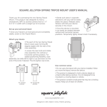
USERS MANUAL FOR VEAVIEN DIMMER 8 4 2 1 84 94 3 54.5 5 1) Button 2) Cover 3) Frame 4) Transparent part 5) Base 6) Screw of the claw 7) Clips 8) Potentiometer axle 6 7 Normal Connection Diagram Veavien Connection Diagram Veavien Dimmer Neutral (N) Line (L) Neutral (N) Line (L) Veavien Dimmer Technical Features: Assembly: Filtered, so it does not interfere with radio waves (with Toroid coil). Depth of mounting box shall be min. 41 mm Fuse (2,5 A). 1- The cable connections should be done as shown in the connection diagram. 220V~, 50-60Hz. Push button, ON / OFF system and light intensity adjustment feature Compatible to use with normal connection an Veavien connection Min.60 Watt - Max.500 Watt for incandescent lamps and halogen lamps with tube- shaped bulbs Min.100 Watt - Max.400 Watt for low voltage white coil lamps that operate via transformers with iron core coils. 2- Place the base (5) in the mounting box and tighten the screws of the claws (4) with an appropriate screwdriver. 3- Transparent parts should be put in the slot on the side of frame. 4- Place the frame (3) on the base and push the dimmer cover (2) so that it will click with the clips (6) on the base (5). 5- Button shuld be put according to direction of D profile of potentiometer axle. Veavien Switch Operation Principles and Properties It can be connected to a Veavien switch that can control one more lamps from two separate points and the required lighting level can be achieved. It is turned on and off by pressing the push button. The lighting level can be adjusted by rotating the button clockwise or anti-clockwise. After you turn the dimmer to either minimum or maximum point, do not force the button to turn any further.