1
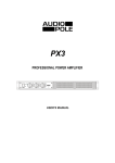
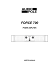
ZONER 4-120
4 CHANNEL MIXER AMPLIFIER
USER’S MANUAL
Index
Safety instructions ……………………………………………………………………….. 2
1. Introduction ………………………………………………………………………….. 3
2. Features…………………………………………………………………………….… 3
3. Controls and Settings…………………………………….…………….……...….… 4
4. Installations Hints …..…………………………………….…………………..…….. 7
5. Example ……..……………………………….……………………….………..….… 7
6. Technical Specifications…..………………………………………………..…..…... 8
7. Warranty ………………………………………………………………………….….. 8
1
Important Safety Instructions
This symbol, wherever used, alerts you to the presence of un-insulated and dangerous voltages
within the product enclosure. These are voltages that may be sufficient to constitute the risk of
electric shock or death.
This symbol, wherever used, alerts you to important operating and maintenance instructions.
POWER SUPPLY
Ensure that the insource voltage (AC outlet) matches the voltage rating of the product. Failure to do so could
result in damage to the product and possibly the user. Unplug the product before electrical storms occur and
when unused for long periods of time to reduce the risk of electric shock or fire.
EXTERNAL CONNECTION
Always use proper ready-made insulated mains cabling (power cord). Failure to do so could result in
shock/death or fire. If in doubt, seek advice from a registered electrician.
DO NOT REMOVE ANY COVERS
Within the product are areas where high voltages may present. To reduce the risk of electric shock do not
remove any covers unless the AC mains power cord is removed. Covers should be removed by qualified service
personnel only. No user serviceable parts inside.
FUSE
To prevent fire and damage to the product, use only the recommended fuse type as indicated in this manual. Do
not short-circuit the fuse holder. Before replacing the fuse, make sure that the product is OFF and disconnected
from the AC outlet.
PROTECTIVE GROUND
Before turning the unit on, make sure that it is connected to Ground. This is to prevent the risk of electric shock.
Never cut internal or external Ground wires. Like wise, never remove Ground wiring from the Protective Ground
Terminal.
OPERATING SAFETY INSTRUCTIONS
Read these instructions. Follow all instructions. Keep these instructions. Do not discard. Heed all warnings. Only
use attachments/accessories specified by the manufacturer.
POWER CORD AND PLUG
Do not tamper with the power cord or plug. These are designed for your safety. Do not remove Ground
connections! If the plug does not fit your AC outlet seek advice from a qualified electrician. Protect the power
cord and plug from any physical stress to avoid risk of electric shock. Do not place heavy objects on the power
cord. This could cause electric shock or fire.
SERVICING
Refer all servicing to qualified service personnel only. Do not perform any servicing then those instructions
contained within this User’s Manual.
DISPOSAL
This symbol indicates that the disposal of this product is submitted to local regulations. Please
contact your local dealer.
2
1
Introduction
Thank you for purchasing Audiopole ZONER 4-120. This mixer amplifier has been specifically designed for
commercial applications. It is an ideal solution for bars, restaurants, retail outlets, office building, and other
applications where paging and background music are required.
ZONER 4-120 combines 4 x 120 W amplifier modules with a five channel mixer; it is a versatile and easy
operating paging system.
Every single source can be routed to one of the four amplifiers to drive independent zones with their own
program.
Every amplifier module has its own control volume and speakers can be connected to 4 Ω, 8 Ω, 25 V, 70 V and
100 V strip terminals available on the rear panel.
The signal of the four output channels can be monitored via a headphone and the level can be adjusted with
the help of 4 Led indicators.
ZONER 4-120 is equipped with a priority system triggered by microphone 1 or a tel. paging signal. It can be
activated with a contact switch as well.
2
Features
• 4 x 120 W
• 4 Ω, 8 Ω, 25 V, 70 V, 100 V outputs
• Five channel mixer
• EQ
• Full routing and monitoring
• Output signal level indicators
• Combo balanced XLR and ¼” Jack inputs,
• Barrier strip output terminals,
• Three unit rack mount (3U)
3
3
Controls and Settings
Front Panel
1
2
6
3
5
8
7
4
12
11
9
1 - GAIN
Input sensitivity. To be adjusted according to the signal source.
2 - TREBLE
Treble control. Neutral correction corresponds to the central position of the knob.
3 - BASS
Bass control. Neutral correction corresponds to the central position of the knob.
4 - MUTE
Button to mute the channel input signal. When activated, the red Led flashes
5 - VOL
Channel volume.
6 - Z1, Z2, Z3, Z4
Channel routing switches assigning the input channel to the zone outputs.
7 - PHONE
35 mm stereo phone Jack input for headphone.
8 - PHONE VOLUME
Output volume for headphone.
9 - ZONE VOLUME
Zone Output volume. The 6 segment Led display the output level.
10 - MONITOR
Button to route the Zone outputs to the Monitor output.
11 - MONITOR VOLUME
Volume of the monitor output.
12 - PL
Power On mode indicator.
13 - POWER
Power switch
4
10
13
3
Controls and Settings
Back Panel
14
16
25
15
24
23
21
20
22
17
18
26
28
27
19
14 - FAN
The fan starts cooling as soon as the temperature reaches 50°C. The fan speed increases with the
temperature. Do not obstruct the entries and exits of air for the cooling of the device. Any impediment to the
free movement of air in the unit may cause a failure not covered by the warranty.
15 - POWER SOCKET, FUSE
Before any connections make sure that the power cable is not damaged. The connection to the mains supply
must have an earth connection. The mains voltage supplied must conform with the electrical characteristics of
the appliance.
The fuse compartment is located above the power connector. In the event of failure, use a fuse with the same
electrical characteristics.
16 - MAINS VOLTAGE
Voltage selector 115 V or 230 V AC.
17 - CH 1, CH 2, CH 3, CH 4
Input connector for Microphone or line source using combo balanced XLR / ¼” jack . CH 1 is the priority input.
When the presence of a signal is detected on input 1, CH 2 to CH 5 are attenuated.
18 - Line / Phantom / Mic
3 positions selector for input signal type. Select “Line” for line level signals, “Mic” for dynamic microphone and
“Phantom” for electrets microphones. The Phantom power supply delivers 15 V.
19 - CH 5
Stereo input for source devices like CD or MP3 players.
20 - Tel. Paging
Terminals for a message player. When the presence of a signal is detected , CH 2 to CH 5 are attenuated.
The signal can be routed to any of the four zones.
21 - TEL Zone
Dip switches to assign the priority message (20) to any of the four zones. The zone is selected when the
corresponding switch is in low position.
22 - TEL Volume
Volume setting of the priority message when it is assigned to the zones.
5
3
Controls and Settings
23 - Priority
When these terminals are short circuit (e.g. using an electrical switch), the audio signal of CH 2 to CH 5 are
attenuated.
24 - Monitor 1W 8 Ω
This terminal can be used for monitoring, using a simple 8 Ω passive speaker. The output delivers 1 W. This
output is controlled by the MONITOR VOLUME (11) knob on the front panel.
25 - Monitor Line Out
Output also controlled by the MONITOR VOLUME (11) knob on the front panel and to be connected to
external amplification system.
26 - Zone Line Out
Zone balanced output to be used with external amplifier devices if necessary.
27 - Power Amp. Output 25 / 70 / 100 V
Powered zone outputs requiring speakers equipped with 25 V / 70 V or 100 V line transformers and a parallel
connection.
Caution, the sum of the powers of the speakers must not exceed the nominal power of the output
amplifier. For example, it will not be possible to use more than 12 speakers 10 W on the same zone.
When manipulate the speaker connectors, make sure that the power is turned off, then replace the plastic cap
on the barrier strip in order to avoid any electric shock.
28 - Power Amp. Output 4 Ω / 8 Ω
These terminal can be used with conventional low impedance speaker if long distance connections are not
necessary. Be aware not using loads less than 4 Ω at risk of damaging the amplifier.
6
4
5
Installations Hints
In case of installation in cabinet or rack, ensure the ventilation requirements. The depth of the unit is 395 mm.
The dimensions in height is 3 units Rack (132 mm).
Do not position high-gain audio equipment like preamplifiers or recorders just above or below the amplifier.
Despite the protections of the radiation device, magnetic fields can induce hum in unscreened ancillary
equipment.
Do not obstruct the entrance and exits of air for the cooling of the amplifier. Any impediment to the free
movement of air in the amplifier may cause a failure not covered by the warranty.
The amplifier use in an environment where the air is confined or polluted requires frequent internal cleaning.
Smoke and dust particles accumulated inside the appliance may cause failures not covered by the warranty.
This cleaning should be done by qualified personnel.
Before any work on the wiring, be sure to turn the control knobs fully counterclockwise and turn off the
amplifier.
Only use good quality speaker cables, unshielded.
Use good quality audio cables, shielded, for inputs. A balanced connection is recommended to keep a signal
without degradation.
Example
Horn
PRIORITY
Switch
Speaker
Column
Speaker
Message Player
Amplifier
Recorder
CD / MP Player
Microphone
Tuner
Table Microphone
Recorder
7
6
Technical Specifications
Power
4 x 120 W rms
Frequency response
50 - 17 000 Hz (-3dB)
THD
S/N ratio
< 0,5% @ 1kHz - rated power
Microphone: > 60 dB
Line: > 70 dB
Tel. Paging: > 60 dB
Mic.: -50 dB balanced
Phantom power: 15 V
Line: -10 dB balanced
Line: -10 dB unbalanced
Low: ± 10 dB - 100 Hz
High: ± 10 dB - 10 kHz
4 Ω, 8 Ω
25 V, 70 V, 100 V
Input sensitivity
CH 1-4
CH 5
EQ
Speaker outputs
Monitor output
1 W rms / 8 Ω
Headphone output
Controls
1 V / 47 Ω
Gain x 5 : CH 1-5
Volume x 5 : CH 1-5
Volume x 3: Tel. Paging, Monitor, Phone
Volume x 4: Zone 1 - 4
High x 5 : CH 1-5
Low x 5 : CH 1-5
Mute x 5 : CH 1-5
Line/Phantom/Mic x 4 : CH 1-4
Stereo x 1 : CH 5
Tel. paging selector x 4 : Zone 1-4
Zone Monitor. x 4 : Zone 1-4
Power ON
Zone level x 4 : Zone 1-4
Monitor level x 1
MUTE x 5 : CH 1-5
115/230 V 60/50 Hz - 400 VA
483 x 132 x 395 mm
20.5 kg
Indicators
Power supply/consumption
Dimensions (L x H x D)
Weight
7
Warranty
This device is warranted parts and labor against any manufacturing defects for a period of two years from the
date of purchase by the first user.
Conditions
1.
2.
3.
4.
5.
The unit has been installed and implemented by observing the safety instructions in this operating manual.
The device was not diverted from its destination, either voluntary or accidental, and suffered no
deterioration or modification other than those described here or explicitly authorized by AUDIOPOLE.
All modifications or repairs have been carried out by an authorized service station.
The defective product must be returned with the dealer who made the sale or to an authorized service
station with proof of purchase.
The device was properly packaged to avoid damage in transport.
8
22, rue Édouard Buffard, Z.A.C. de la Charbonnière, Montévrain - 77771 Marne-la-Vallée Cedex 4 - France
Tél : + 33 (0)1 60 54 32 00 - Fax : + 33 (0) 1 60 54 31 90 - www.audiopole-pa.fr